Table of Contents
Advertisement
Quick Links
Advertisement
Table of Contents
Troubleshooting

Related Manuals for Bionet BM1


Summary of Contents for Bionet BM1
- Page 1 BM1 User’s Manual BM1 User’s Manual Patient Monitor Rev. 1.4...
-
Page 2: Table Of Contents
BM1 User’s Manual Table of Contents BM1 User’s Manual ................0 Table of Contents....................... 1 B A S I C .................... 10 1.1 CE Standard Information ...................11 1.2 Read before Use......................13 How to Contact Us ......................13 Warranty Period ......................14 Warning, Caution, Note .................... - Page 3 BM1 User’s Manual How to Recycle the Battery ..................... 37 1.7 DISPLAY MODE ( MONITOR OR SPOT ) ..............38 MONITORING MODE ................ 39 1. General Operation ................ 40 1.1 General Manu Operation ................... 40 Screen Composition ......................40 Menu Selection........................ 41 Menu Composition ......................
- Page 4 BM1 User’s Manual SET DATE & TIME ......................61 SET TIME ........................61 SET DATE ........................62 SWEEP SPEED ......................62 DEMO ..........................63 USB FILE COPY ......................63 USER SERVICE......................66 SET UNIT NAME......................66 SET BED NUMBER ......................67 AC FILTER ........................
- Page 5 BM1 User’s Manual SPO2 Messages ......................83 6. NIBP ....................84 6.1 Outline ......................... 85 6.2 NIBP Data Window ..................... 87 6.3 NIBP Data Setup......................88 ALARM ..........................88 ALARM LIMIT ........................89 ALARM SOUND ......................90 CUFF SIZE ........................90 UNIT SELECT .........................
- Page 6 BM1 User’s Manual ALARM SOUND ......................110 EtCO2 SWEEP SPEED ....................111 WAVEFORM SCALE (Measured waveform scale setting) .......... 111 SETUP (Various setting) ....................112 APNEA DETECT ......................115 8.4 TROUBLESHOOTING ....................119 9. DEFAULT SETTING VALUE ............120 1. Adult Mode........................120 2.
- Page 7 BM1 User’s Manual Alarm ICON ........................142 2.5 Alarm Setup ......................143 2.6 Alarm Limit ....................... 143 2.7 Alarm Volume ......................144 2.8 Alarm Level ....................... 144 2.9 Nurse Call ......................... 145 2.10 Alarm Sound......................145 3. SAVE RECORD ................146 3.1 Outline ........................
- Page 8 BM1 User’s Manual 5.4 USER SERVICE ......................164 5.5 SYSTEM ........................168 5.6 KEY SOUND ......................168 6. NIBP .................... 170 6.1 Outline ........................171 6.2 NIBP Data Window ....................173 6.3 NIBP Data Setup....................... 174 ALARM LIMIT ........................ 174 CUFF SIZE ........................
- Page 9 BM1 User’s Manual ALARM LIMIT ........................ 188 TEMP MODE ......................... 189 PROBE SITE (Measurement Position) ................. 190 UNIT SELECT ....................... 191 8.4 TROUBLESHOOTING ....................191 Check list ........................191 TEMP Message ......................191 9. DEFAULT SETTING VALUE ............192 1. Adult Mode........................192 2.
- Page 10 BM1 User’s Manual Note The information in this manual only applies to BM1 patient monitor software version 1.034 . Due to continuing product innovation, specifications in this manual are subject to change without notice. Rev. 1.4...
-
Page 11: B A S I C
BM1 User’s Manual B A S I C 1.1 CE Standard Information 1.2 Read before Use Warranty Period Warning, Caution, Note General Precaution on Environment General Precaution on Electric Safety Equipment Connection, Maintenance & Washing Equipment Connection Product Components Product Outline... -
Page 12: Ce Standard Information
BM1 User’s Manual 1.1 CE Standard Information Electromechanical safety standards met: Information supplied by the manufacturer of medical devices EN 60601-1:1990+A1:1993+A2:1995+A13:1996 (IEC 60601-1:1988+A1:1991+A2:1995) Medical electrical equipment Part1: General requirements for safety EN 60601-1-2:2001 + A1:2006 (IEC 60601-1-2:2001+A1:2004) Electromagnetic Compatibility Requirement and tests... - Page 13 BM1 User’s Manual 10. EN 1060-1:1995+A2:2009, EN 1060-3:1997+A2:2009: Performance test for NIBP Non-invasive sphygmomanometers- Part 1: General requirements, Part 3: Supplementary requirements for electro-mechanical blood pressure measuring systems 11. EN ISO 14971:2012 Medical devices - Application of risk management to medical devices 12.
-
Page 14: Read Before Use
BM1 User’s Manual 1.2 Read before Use BIONET services are always available to you. The following are addresses and phone numbers for information, services, and product supplies. How to Contact Us Product Supply Bionet Ltd. Information Address : #1101 11F E&C Venture Dream Tower3 38-21, Digital-Ro 31-Gil, Guro-Gu, Seoul , REPUBLIC OF KOREA 152-719 Overseas sales dept. -
Page 15: Warranty Period
“Consumer’s protection law” noticed by Economic Planning Dept. We provide a 1-year warranty period. We will repair or replace any part of the BM1 found to be defective in usual operating circumstance for free to you. This warranty does not apply to any defect caused by improper use, misuse or abuse. -
Page 16: Warning, Caution, Note
BM1 User’s Manual Warning, Caution, Note For special emphasis on agreement, terms are defined as listed below in user’s manual. Users should operate the equipment according to all the warnings and cautions. Warning To inform that it may cause serious injury or death to the patient, property damage, material losses against the “warning”... -
Page 17: General Precaution On Environment
BM1 User’s Manual General Precaution on Environment - Do not keep or operate the equipment in the environment listed below. Avoid placing in an area exposed to moisture. Avoid exposure to direct Do not touch the equipment sunlight with wet hands. - Page 18 BM1 User’s Manual CAUTIONS Before Installation Compatibility is critical to safe and effective use of this device. Please contact your local sales or service representative prior to installation to verify equipment compatibility. Defibrillator Precaution Patient signal inputs labeled with the CF and BF symbols with paddles are protected against damage resulting from defibrillation voltages.
- Page 19 BM1 User’s Manual For this reason make sure that all external devices operated in the vicinity of the monitor comply with the relevant EMC requirements. X-ray equipment or MRI devices are possible sources of interference as they may emit higher levels of electromagnetic radiation.
- Page 20 MPSO as it will increase the chance of the single protective earth conductor interruption. Negligence BIONET does not assume responsibility for damage to the equipment caused by improperly vented cabinets, improper or faulty power, or insufficient wall strength to support equipment mounted on such walls.
- Page 21 BM1 User’s Manual NOTES Power Requirements Before connecting the device to the power line, check the voltage and frequency. Ratings of the power line are the same as those indicated on the unit’s label. If this is not the case, do not connect t he syst em to t he pow er line unt il you adjust t he unit to mat ch t he power sour ce.
-
Page 22: General Precautions On Electrical Safety
1. Be sure that AC power supply line is appropriate to use. (AC100 - 240V) 2. Be sure that the power source is the one supplied from Bionet. (DC15V, 2.0A) 3. Be sure that the entire connection cable of the system is properly and firmly fixed. - Page 23 BIONET or its representatives. Maintenance and Washing Equipment Connection There are various methods to clean the BM1 and its accessories. Please follow the methods mentioned below to avoid unnecessary damage or contamination to the Equipment. We do not repair free of charge regardless of warranty period if it is contaminated or damaged with using dangerous material not approved for washing.
-
Page 24: Cleaning Applied Parts
BM1 User’s Manual Cleaning Applied Parts Do not permit any liquid to enter the monitor case and avoid pouring it on the monitor while cleaning. Do not allow water or cleaning solution to enter the connectors of jack cover. Recommended cleaning agents: Alcohol (Ethanol 70%, Iosopropanol 70%, Window cleaner) Ammonias (Dilution of ammonia <3%, Window cleaner) - Page 25 Warning Check the electrodes of batteries before changing them. · Operate BM1 with internal electric power supply when unsure of external ground connection or installation occur. · Remove the 1st battery when not using equipment for a while to avoid any damage.
-
Page 26: Product Components
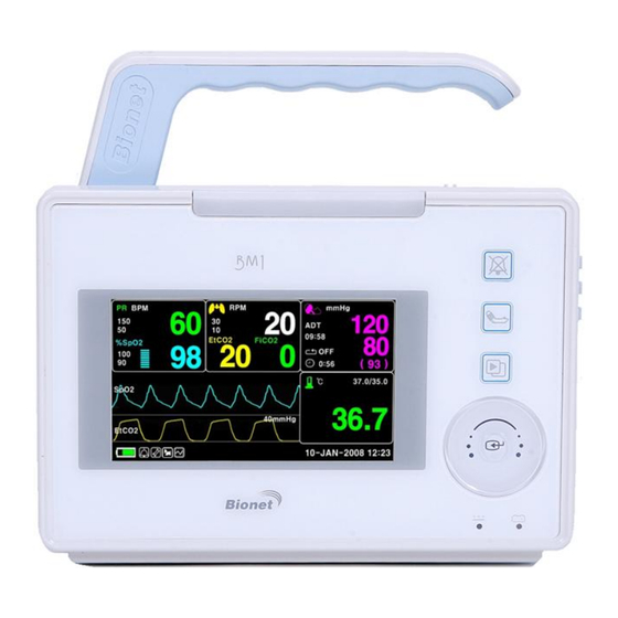
EtCO2 on its LCD screen and monitoring parameter, and alarming. Principal Characters of Product BM1 is a small-size multifunctional monitoring device for a patient designed to for easy usage during movement. It features DC power supply (Bridgepower,JMW128,DC 15V,2.0A). The equipment also measures major parameters such as SpO2, NIBP, temperature and pulse rate, EtCO2 displaying it on a 4.3-inch color TFT LCD screen. -
Page 27: Product Configuration
Warning In order to avoid electrical shock, do not open the cover. Disassembling of the equipment should be done only by the service personnel authorized by BIONET Warning Users must pay attention on connection any auxiliary device via LAN port or nurse calling. -
Page 28: Product Body Configuration
BM1 User’s Manual Product Body Configuration FRONT Silence Alarm NIBP Go/Stop Display Mode / Home Touch Wheel Select key Battery Power LED DC Power LED BACK TOUCHKEY LOCK Output port Rev. 1.4 1.BASIC... - Page 29 BM1 User’s Manual Right Side SpO2 cable Connector SpO2 IPX1 Temperature Probe IPX7 Connector NIBP Hose Connector EtCO2 Module POWER Connector ON/OFF Left Side EXT. Power USB port (S/W Output Port Upgrade) 5.0V USB Host port ( USB memory ,...
-
Page 30: Accessories
BM1 User’s Manual Accessories Cable + Extension Cable NIBP Cuff+ Extension cable Temperature sensor (YSI 400 series, Option) Rev. 1.4 1.BASIC... -
Page 31: Equipment Sign
BM1 User’s Manual Equipment Sign ATTENTION : Consult accompanying documents TYPE CF APPLIED PART : Insulated (floating) applied part suitable for intentional external and internal application to the patient including direct cardiac application. "Paddles" outside the box indicate the applied part is defibrillator proof. -
Page 32: Dc Power Input Port
BM1 User’s Manual Power On/Off USB port Output port DC Power Output LAN port Nurse Call port IN OUT PORT VGA Output DC Input Indicator Battery Input Indicator DC Power Input port Rev. 1.4 1.BASIC... - Page 33 BM1 User’s Manual NIBP Temperature Pulse Rate EtCO2 / Respiration Silence Alarm Display mode selection / Home Rev. 1.4 1.BASIC...
-
Page 34: Function And Key
External Function The front panel of this product consists of an LCD screen and four Touch function keys and one Touch Wheel. Operating the BM1 Patient Monitor Operation Key 1. Alarm: Stop alarm sound. First press stops the current alarm for one minute Second press stops the all alarm for five minutes. -
Page 35: Standard Power Supply Application
BM1 User’s Manual 1.5 Standard Power Supply Application DC Power DC Power LED is lighted on when the DC Power is plugged into the inlet at the back of the product. A press of the power key makes the machine ready for use. -
Page 36: Battery Power Supply Application
BM1 User’s Manual 1.6 Battery Power Supply Application Battery power can be supplied for enabling a portable use or for use during DC power failure. Operation 1. Battery Power LED is lighted on when the machine is in use. 2. The DC/battery power is only sustainable for 4.5 hour. - Page 37 BM1 User’s Manual When the battery power remains 25%, the Low Battery icon is displayed. The power is automatically cut off after 5 minutes from the appearance of the message. The machine will no longer operate when the “Low Battery” indication is on. Charge the batteries with the power adaptor, which BIONET provided.
-
Page 38: The Impact Of Lithium-Ion Battery Technology On The Battery
12 months. BIONET recommends that you remove the battery and store it near the monitor until it is needed for transport. -
Page 39: Display Mode ( Monitor Or Spot )
BM1 User’s Manual 1.7 DISPLAY MODE ( MONITOR OR SPOT ) You can selected display mode ( Monitoring and Spot). MONITOR : Refer to the Monitor chapter of this manual for details. SPOT : Refer to the SPOT chapter of this manual for details. -
Page 40: Monitoring Mode
BM1 User’s Manual MONITORING MODE 1. General Operation 2. Patient/Data Management 3. Setup 4. Trend 5. SpO2 6. NIBP 7. Temperature 8. EtCO2 9. Default Setting Value Rev. 1.4... -
Page 41: General Operation
BM1 User’s Manual 1. General Operation 1.1 General Manu Operation Screen Composition Real Time Wave Parameter Window Windows mmHg 09:58 EtCO2 FiCO2 %SpO2 ( 93 ) 0:56 42.0 ℃ SpO2 35.0 ALARM MAIN VOLUME: 36.7 MENU LIMITS 40mmHg EtCO2 NURSE... -
Page 42: Menu Selection
BM1 User’s Manual Menu Selection mmHg 09:58 EtCO2 FiCO2 %SpO2 Turn or touch ( 93 ) the wheel. 0:56 42.0 ℃ SpO2 35.0 36.7 40mmHg EtCO2 10-JAN-2008 12:23 When the Trim Knob Key is turned, menus are selected in the order indicated above. The above screen shows that the MORE menus is selected. - Page 43 BM1 User’s Manual Numerical value sign widow This window displays a measured parameter, function setup, and the boundary of parameter values. Pulse rate Alarm limit %SpO2 value % SpO2 Menu selection by using Touch wheel key As the key is turned to the right, the menu selection moves clockwise. As the key is turned to the left, the menu selection moves counterclockwise.
- Page 44 BM1 User’s Manual > MAIN VOLUME : MENU PREV 100% MENU Word feature menu The following figure shows the screen where the word sequence menu is activated within the word sequence correction menu. Here, the cursor moves over the words when the touch wheel key is turned in the clockwise direction.
- Page 45 BM1 User’s Manual Operation menu The setup value changes without a selection when the menu is moved. ADMIT CHANGE MAIN TYPE : ADMIT ADMIT MENU INFO HEIGHT WEIGHT PREV DEFAULT UNIT: UNIT: MENU SETTING MAIN ADMIT CHANGE ADMIT MENU TYPE...
-
Page 46: Patient/Data Management
BM1 User’s Manual 2. PATIENT/DATA MANAGEMENT 2.1 ADMIT CHANGE ADMIT INFO DISCHARGE HEIGHT WEIGHT 2.2 ALARM ALL LIMITS ALARM VOLUME ALARM LEVEL ALARM REVIEW ALARM LIST SAVE ALARM LEVEL NURSE CALL Rev. 1.4... -
Page 47: Admit
BM1 User’s Manual 2.1 ADMIT Additional setups are made for each parameter function. One can make an overall setup for the entire monitor system. CHANGE ADMIT INFO : The CHANGE ADMIT INFO option allows you to change or enter information pertinent to the monitored patient. -
Page 48: Change Admit Info
BM1 User’s Manual CHANGE ADMIT INFO Last and first name (11 letters for each), sex (male or female), date of birth, weight, height, and patient ID (13 characters) ADMIT CHANGE MAIN TYPE: ADMIT DISCHARGE MENU INFO HEIGHT WEIGHT PREV DEFAULTS... - Page 49 BM1 User’s Manual Admit Patient ID using the Barcode Scanner Using the USB barcode scanner, this product can admit the PATIENT ID in barcode form to the device. First connect the barcode scanner to the USB HOST connecter on the left side (from the front) of the device, as shown below.
-
Page 50: Discharge ( Discharge Patient )
BM1 User’s Manual DISCHARGE ( Discharge Patient ) The CHANGE ADMIT INFO option allows you to change or enter information pertinent to the monitored patient. Patient information and all numbers change to standard, and the screen displays ADMIT CHANGE MAIN... -
Page 51: Height
BM1 User’s Manual HEIGHT Unit of height is set as Cm / Inches. ADMIT CHANGE MAIN TYPE : ADMIT ADMIT MENU INFO HEIGHT WEIGHT PREV DEFAULT UNIT: UNIT: MENU SETTING ADMIT CHANGE MAIN TYPE : ADMIT ADMIT MENU INFO HEIGHT... -
Page 52: Alarm
BM1 User’s Manual 2.2 ALARM When you select the icon in the main screen to display the menu on page48. Alarm is divided into two, alarm for the patient’s condition and for the product’s condition. The patient’s alarm sound differs in order and volume according to the levels of HIGH, MEDIUM, LOW and MESSAGE. -
Page 53: Alarm Icon
BM1 User’s Manual ALARM LIMITS:The machine enables one to see and change the limits of alarm for all parameter functions. ALARM VOLUME:volume of each alarm can be adjusted in 10 step. ALARM LEVEL:Priority of each parameter alarm can be set up. -
Page 54: All Limits
BM1 User’s Manual ALL LIMITS The ALL Limits menu option allows you to view the high and low alarm limits and unit of measurement for each parameter currently monitored. ALARM MAIN VOLUME: MENU LIMITS NURSE PREV ALARM ALARM CALL: MENU... -
Page 55: Alarm Volume
BM1 User’s Manual ALARM VOLUME Set the alarm volume to be set at 10 grades. ALARM MAIN VOLUME: MENU LIMITS NURSE PREV ALARM ALARM CALL: MENU LEVEL REVIEW ALARM > MAIN VOLUME: MENU PREV 100% MENU ALARM LEVEL Set the order of priority in each alarm. -
Page 56: Parameter Level
BM1 User’s Manual PARAMETER LEVEL PARAMETER ALARM LEVELS RETURN ALARM LEVEL SPO2-% MEDIUM SPO2-R AWRR MESSAGE EtCO2 MESSAGE FiCO2 MESSAGE APNEA MESSAGE NIBP MEDIUM TEMP MESSAGE CHECK PROBE MESSAGE PROBE OFF MESSAGE LOW BATTERY PARAMETER ALARM LEVEL2 PARAMETER ALARM LEVELS 2... -
Page 57: Alarm Review
BM1 User’s Manual ALARM REVIEW After an alarm is triggered the alarms and data wave pattern can be reviewed. Set up for priority of each parameter alarm. ALARM MAIN VOLUME: MENU LIMITS NURSE PREV ALARM ALARM CALL: MENU LEVEL REVIEW... -
Page 58: Save Condition
BM1 User’s Manual ALARM REVIEW ALARM REVIEW < RETURN HIGH 2009/04/02 13:20:10 SpO2-%:92% SpO2-R: 80BPM NIBP:120/80(93) TEMP:35.7'C EtCO2: 38 FiCO2:0 AWRR: 18 13:20:09 13:20:10 13:20:11 SAVE CONDITION This determines the order in which triggered alarms are saved. SAVE MAIN ALARM... -
Page 59: Nurse Call
BM1 User’s Manual NURSE CALL When an alarm is triggered, this activated the NURSE CALL function. ALARM MAIN VOLUME: MENU LIMITS NURSE PREV ALARM ALARM CALL: MENU LEVEL REVIEW ALARM MAIN VOLUME: MENU LIMITS NURSE PREV ALARM ALARM CALL: MENU... -
Page 60: Setup
BM1 User’s Manual 3. SETUP 3.1 SETUP DISPLAY DEMO USB FILE COPY USER SERVICE MAKER SERVICE Rev. 1.4... -
Page 61: Setup
BM1 User’s Manual 3.1 SETUP When you select the icon in the main screen to display the menu below DISPLAY : screen set menu USER SERVICE : This is the menu to set the connection used to interface with an external computer MAKER SERVICE : This is the basic adjustment menu used to adjust the features of this product. -
Page 62: Set Para
BM1 User’s Manual SET PARA Select measurement function to use AUTO : Automatically parameter windows activate MAIN MENU PARA DATE & TIME SWEEP PREV SPEED: MENU 25mm/s PARAMETER WINDOW SET RETURN WINDOW ON/OFF AUTO SPO2 EtCO2 NIBP TEMP SET DATE & TIME It has sub menu to set date and time. -
Page 63: Set Date
BM1 User’s Manual MAIN MENU TIME: 10 : 58 : 01 PREV MENU SET DATE Set date of equipment MAIN SET TIME MENU DATE PREV MENU MAIN MENU DATE: 14-APR-2009 PREV MENU SWEEP SPEED Set speed of drawing wave signal pattern in this widow. -
Page 64: Demo
BM1 User’s Manual DEMO Set ON/OFF DEMONSTRATION of equipment. MAIN USER DISPLAY MENU SERVICE PREV DEMO: MAKER SOUND: MENU SERVICE MAIN USER DISPLAY MENU SERVICE PREV DEMO: MAKER SOUND: MENU SERVICE USB FILE COPY Use the SAVE button in the USB FILE COPY menu to export records to a USB flash drive. - Page 65 BM1 User’s Manual The following message will appear if there is no USB MEMORY after the user commanded SAVE function MAIN FILE MENU USB MEMORY CHECK! COPY PREV SAVE CANCEL MENU Display the data saving task progress The number on left indicates files saved so far, while the number on right shows the total number of files to be saved.
- Page 66 BM1 User’s Manual The picture below is stored as a Microsoft Excel file is opened the screen ① is the date the data entry, data in this column to see normal cell to form "one - Month - Year” is set.
-
Page 67: User Service
BM1 User’s Manual USER SERVICE The user is able to set the set UNIT NAME, BED NUMBER, external Wireless equipment power , communication parameters, and power supply filter. MAIN USER DISPLAY FILE MENU SERVICE COPY PREV DEMO : MAKER SOUND:... -
Page 68: Set Bed Number
BM1 User’s Manual SET BED NUMBER Set up for patient bed number. Allowable setters are from 0~ 9, A ~ Z . SET BED MAIN W-LAN: UNIT NUMBER MENU NAME : 00A DISPLAY PREV AC FILTER: SYSTEM MODE: MENU 50HZ... -
Page 69: W-Lan
BM1 User’s Manual W-LAN W-LAN power can be supplied for enabling a External wireless LAN equipment use. SET BED MAIN W-LAN: UNIT NUMBER MENU NAME : 00A DISPLAY PREV AC FILTER: SYSTEM MODE: MENU 60HZ MONITOR DISPLAY MODE ( MONITOR or SPOT ) You can selected Monitoring display mode or Spot display mode. -
Page 70: Key Sound
BM1 User’s Manual KEY SOUND Set ON/OFF Key Sound of equipment. MAIN USER DISPLAY FILE MENU SERVICE COPY PREV DEMO: MAKER SOUND: MENU SERVICE MAIN USER DISPLAY FILE MENU SERVICE COPY PREV DEMO: MAKER SOUND: MENU SERVICE MAKER SERVICE Maker service is a menu is used by manufacturers. -
Page 71: Trend
BM1 User’s Manual 4. TREND 4.1 TREND GRAPHIC TREND TABULAR TREND Rev. 1.4... -
Page 72: Trend
BM1 User’s Manual 4.1 TREND When you select the icon in the main screen to display the menu below. TREND shows saved data graphically displayed with numeric values. Real-time data recording duration is 1 minute. Amount of saving time is for this data will be saving for 128hours. -
Page 73: Graphic Trend
BM1 User’s Manual GRAPHIC TREND Wave Data can be stored and seen according to section. MAIN GRAPHIC TABULAR MENU TREND TREND PREV MENU GRAPHIC TREND 07-APR-2009 13:00 SpO2-% SpO2-R NIBP TEMP ( 98 ) ( 80 ) (120/80/93) ( 36.7) -
Page 74: Time Period
BM1 User’s Manual TIME PERIOD One can set up and store data and time that one can see in a screen. GRAPHIC TREND 07-APR-2009 13:00 AWRR EtCO2 FiCO2 ( 20 ) ( 38 ) ( 0) 150 RPM 100mmHg 10mmHg... -
Page 75: Tabular Trend
BM1 User’s Manual TABULAR TREND One can see the stored data at the time previously set up. MAIN GRAPHIC TABULAR MENU TREND TREND PREV MENU TIME INTERVAL One can store data and set up time. TABULAR TREND 10-APR-2009 13:00 10-APR... -
Page 76: Spo
BM1 User’s Manual 5. SpO 5.1 Outline Connector Location and Measuring Cable 5.2 SpO2 Data Window 5.3 SpO2 Data Setup SWEEP SPEED RATE VOLUME ALARM ALARM LIMIT 5.4 Trouble Shooting Rev. 1.4... -
Page 77: Outline
BM1 User’s Manual 5.1 Outline SPO2 monitoring is a noninvasive technique used to measure the amount of oxygenated hemoglobin and pulse rate by measuring the absorption of selected wavelengths of light. The light generated in the probe passes through the tissue and is converted into an electrical signal by the photodetector in the probe. -
Page 78: Spo2 Data Window
BM1 User’s Manual 5.2 SpO Data Window %SpO , PR Alarm Limit: Indicates an %SpO ,PR alarm limit Pulse Rate Beats per minute. %SpO2 Oxygen Concentration in the Strength indicators: Blood(SpO2 value) Indicates SpO Strength in a bar graph. : Indicates %SpO in numbers. -
Page 79: Signal And Data Validity
BM1 User’s Manual Signal and Data Validity It is extremely important to determine that the probe is attached to the patient correctly and the data is verifiable. To make this determination, three indications from the monitor are of assistance—signal strength bar, quality of the SPO2 waveform, and the stability of the SPO2 values. It is critical to observe all three indications simultaneously when ascertaining signal and data validity. - Page 80 BM1 User’s Manual Stability of SPO2 Values The stability of the displayed SPO2 values can also be used as an indication of signal validity. Although stability is a relative term, with a small amount of practice one can get a good feeling for changes that are artifactual or physiological and the speed of each.
-
Page 81: Spo 2 Data Setup
BM1 User’s Manual 5.3 SpO Data Setup Turn the rotary wheel on the blue cursor to position the data window (refer to P.78), Select the menu button, and the following window is displayed. ALARM : Menu in which SpO alarm are set up. -
Page 82: Alarm
BM1 User’s Manual ALARM Two menus: ALARM LIMIT, ALARM SOUND provided in the alarm menu RATE MAIN ALARM VOLUME: MENU ALARM LIMIT Number setting of alarm value of %SpO 0 ~ 100 2 is 1. Move the ▶ mark to select from RETURN, SpO or SpO -R, and press. -
Page 83: Alarm Sound
BM1 User’s Manual SPO2 ALARM LIMIT RETURN UNITS HIGH SPO2-% SPO2-R ALARM SOUND Warning sound or message displays configuration menu when an alarm is triggered. ALARM MAIN ALARM SOUND: MENU LIMIT PREV MENU ALARM MAIN ALARM SOUND: MENU LIMIT PREV MENU Rev. -
Page 84: Trouble Shooting
BM1 User’s Manual 5.4 TROUBLE SHOOTING LEAD FAULT Condition When using a reusable finger probe, there is a system alarm to alert you when the probe is off the Monitor. The monitor defaults this “ LEAD FAULT” condition as a System Warning alarm. You can, however, set it as a System ALARM LEVEL in Monitor Defaults. -
Page 85: Nibp
BM1 User’s Manual 6. NIBP 6.1 Outline NIBP Connector Location and Cuff 6.2 NIBP Data Window 6.3 NIBP Data Setup ALARM LIMIT ALARM CUFF SIZE UNIT SELECT INTERVAL STAT INFLATION 6.4 Trouble Shooting Rev. 1.4... -
Page 86: Outline
BM1 User’s Manual 6.1 Outline This function is to measure minimum, Maximum and average blood pressure by using Oscillometric method Position of NIBP Connecter and cuff NIBP Connector SpO2 IPX1 IPX7 ADULT CUFF Note As the value of NIBP can vary according to the age and sex of a patient, the user needs to set up right data in Parameter Menu before measurement. - Page 87 BM1 User’s Manual WARNING Noninvasive blood pressure monitoring is not recommended for patients with extremely high or low heart rate or hypotension, hypertension, arrhythmias. The software algorithm cannot accurately compute NIBP or patients with these conditions. Note As the value of NIBP can vary according to the age and sex of a patient, the user needs to set up right data in parameter Menu before measurement.
-
Page 88: Nibp Data Window
BM1 User’s Manual 6.2 NIBP Data Window Cuff Type: Indicates Cuff size(Adult). Systolic pressure: Indicates the maximum limit of blood pressure mmHg display 09:30 Diastolic blood pressure:Indicates 1 HR the minimum limit of (93) Measurement time 0:54 blood pressure Indicates the completion time of measuring Mean Value:... -
Page 89: Nibp Data Setup
BM1 User’s Manual 6.3 NIBP Data Setup Turn the rotary wheel on the blue cursor to position the data window (refer to P.81), Select the menu button, and the following window is displayed. ALARM: A menu to set the Alarm CUFF SIZE:A menu to select cuff size ( ADT (Adult) , PED(Pediatric) , NEO(Neonate) ) -
Page 90: Alarm Limit
BM1 User’s Manual ALARM LIMIT Alarm setting Numeric Value of Systolic, Diastolic, and mean pressure is 10 ~ 300mmHg. 1. Move the ▶ mark to select one from RETURN, NIBP-S, NIBP-M, or NIBP-D, and press. 2. Press the key at NIBP-S, and move to LOW, and press again.(The user gets the same result regardless of the LOW-HIGH, or HIGH-LOW order.) -
Page 91: Alarm Sound
BM1 User’s Manual ALARM SOUND Warning sound or message displays configuration menu when an alarm is triggered. ALARM MAIN ALARM SOUND: LIMIT MENU PREV MENU CUFF SIZE The user can select a CUF between ADULT and NEONATAL. CUFF MAIN ALARM... -
Page 92: Unit Select
BM1 User’s Manual UNIT SELECT It is a function to set blood pressure measurement unit. The blood pressure measurement unit provides mmHg and kPa. CUFF MAIN ALARM SIZE: MENU UNIT INFLATION: INTERVAL: SELECT: 170mmHg mmHg CUFF MAIN ALARM SIZE: MENU... -
Page 93: Inflation
BM1 User’s Manual Warning Periodically check patient limb circulation distal to the cuff. Check frequently when using auto NBP in 1 and 2 minute intervals. Intervals below 10 minutes are not recommended for extended periods of time. INFLATION It is a function for pressurization pressure. -
Page 94: Troubleshooting
BM1 User’s Manual 6.4 TROUBLESHOOTING NIBP Status Messages Below is a list of system status alarm messages which may be displayed in the NIBP parameter window during monitoring. Status Message Monitor Response Solution System status alarm. OVER Auto mode will shut off after ONE Remove cuff and contact service. -
Page 95: Erroneous Nibp Measurement
BM1 User’s Manual Erroneous NIBP measurement Check for proper cuff size 1. Too small a cuff can give an erroneously high value. 2. Too large a cuff can give an erroneously low value. Check for residual air left in the cuff from a previous measurement. -
Page 96: Temperature
BM1 User’s Manual 7. TEMPERATURE 7.1 Outline Temperature Connector and Measuring Cable 7.2 Temperature Data Window 7.3 Temperature Data Setup ALARM LIMIT UNIT SELECT 7.4 Trouble Shooting Rev. 1.4... -
Page 97: Outline
BM1 User’s Manual 7.1 Outline This function is used to indicate the changes of resistance generated by the changes of temperature in numbers. The function involves the process of transferring the changes into electric signals. Temperature Connector and Measuring Cable... -
Page 98: Temperature Data Window
BM1 User’s Manual 7.2 Temperature Data Window Alarm limit on the least low 42.0 ℃ temperature : 35.0 Indicates temperature limits Unit: 36.7 Temperature: Displays Displays temperature unit. temperature. Note The minimum measuring time required to obtain accurate readings at the specific body site is at least 3 minutes. -
Page 99: Temperature Data Setup
BM1 User’s Manual 7.3 Temperature Data Setup Turn the rotary wheel on the blue cursor to position the data window (refer to P.98), Select the menu button, and the following window is displayed. ALARM: Temperature measurement alarm set UNIT: Temperature measurement unit set... -
Page 100: Alarm Limit
BM1 User’s Manual ALARM LIMIT Setting numeric value is 15.0℃ ~ 45.0℃. 1. Move the ▶ mark to select either RETURN or TEMP, and press. 2. After pressing the cursor at TEMP, move it to LOW, and press. 3. When the color has changed, move the cursor again to select a target value, and press. -
Page 101: Alarm Sound
BM1 User’s Manual ALARM SOUND Warning sound or message displays configuration menu when an alarm is triggered. ALARM MAIN ALARM SOUND : MENU LIMIT PREV MENU ALARM MAIN ALARM SOUND : MENU LIMIT PREV MENU UNIT SELECT Able to select unit with °C, °F. -
Page 102: Troubleshooting
BM1 User’s Manual 7.4 TROUBLESHOOTING Check list 1. The temperature probe(YSI 400 series) is correctly positioned on the patient. 2. Temperature cable is attached to the monitor. 3. Temperature setup is adjusted, if necessary. Follow detailed procedures within this chapter. -
Page 103: Etco2
BM1 User’s Manual 8. EtCO2 8.1 INTRODUCTION Position of EtCO Connector and Accessory EtCO ACCESSORY 8.2 EtCO Parameter Window 8.3 EtCO Parameter Setting Menu 8.4 EtCO Parameter Setting Menu 8.4 Trouble Shooting Rev 1.4... -
Page 104: Introduction
BM1 User’s Manual 8.1 Introduction ETCO2(End-Tidal CO2) is a device to see the concentration of end-tidal carbon dioxide, which uses a method of measurement based on the non-dispersed IR absorption of CO2 using IR ray by sampling a certain part of respiration through pipe during respiration. - Page 105 BM1 User’s Manual EtCO2 accessories for sidestream applications EtCO2 monitoring accessory uses the accessories for LoFlo™ sidestream module of Respironics Company. The CO2 Sampling Cannula for sidestream Non-intubated applications 3468ADU-00 Nasal CO Sampling Cannula ADULT 3468PED-00 Nasal CO Sampling Cannula...
- Page 106 BM1 User’s Manual The airway adapters for sidestream intubated applications 3473ADU-00 Airway Adapter Weight: 4.5 grams Deadspace – adds approximately 7 Kit w/ Dehumidification cc of deadspace Intended for use when Tubing monitoring patients with ET Tube sizes >4.0 mm...
- Page 107 BM1 User’s Manual CAPNOSTAT 5 mainstream CO2 sensor and Mainstream sensor Mainstream sensor connector EtCO2 accessories for mainstream applications EtCO2 monitoring accessory uses the accessories for CapnoStat 5 microstream sensor of Respironics Company. The airway adapters for mainstream intubated applications...
- Page 108 BM1 User’s Manual Connecting the CAPNOSTAT® 5 CO2 Sensor to the Host System 1. Insert the CAPNOSTAT 5 CO Sensor connector into the receptacle of the host monitor as shown in Figure 1. 2. Make sure the arrows on the connector are at the top of the connector and line up the two keys of the connector with the receptacle and insert.
-
Page 109: Etco2 Parameter Window
BM1 User’s Manual 8.2 EtCO2 Parameter Window AWRR AWRR Upper/lower limit value of alarm EtCO2 FiCO2 FiCO2 EtCO2 Upper/lower limit value of alarm: Display of alarm setting range value for concentration of CO EtCO : Display of concentration value of carbon dioxide... -
Page 110: Etco2 Parameter Setting Menu
BM1 User’s Manual 8.3 EtCO2 Parameter Setting Menu Turn the rotary wheel on the blue cursor to position the data window, Select the menu button, and the following window is displayed. ALARM: A menu to set the alarm SWEEP SPEED: Speed is changeable to 6.25, 12.5, 25mm/s. -
Page 111: Alarm Sound
BM1 User’s Manual EtCO2 ALARM LIMIT RETURN UNITS HIGH EtCO2 mmHg FiCO2 mmHg AWRR APNEA The following table shows standard alarm limit of parameter and setting value of scale when setting the label. Adult Neonatal Parameter High Scale High Scale... -
Page 112: Etco2 Sweep Speed
BM1 User’s Manual EtCO2 SWEEP SPEED EtCO2 speed is 6.5mm/s. Speed is changeable to 6.25, 12.5, 25mm/s. SWEEP WAVEFORM MAIN ALARM SPEED: SCALE: MENU 6.25mm/s APNEA DETECT: ZERO SETUP SWEEP MAIN ALARM SPEED: MENU > 6.25mm/s 6.25mm/s 12.5mm/s APNEA 25mm/s... -
Page 113: Setup (Various Setting)
BM1 User’s Manual SETUP (Various setting) Different menus are applied to provide menu and information for handling the EtCO2 module. SWEEP WAVEFORM MAIN ALARM SPEED: SCALE: MENU 6.25mm/s APNEA DETECT: ZERO SETUP - MODULE SETUP MAIN MODULE MODULE MENU SETUP... - Page 114 BM1 User’s Manual - BAROMETRIC PRESSURE: This setting is used to set current Barometric Pressure. - GAS TEMPERATURE: This setting is used to set temperature of the gas mixture. This setting is useful when bench testing using static gasses where the temperature is often room temperature or below.
- Page 115 BM1 User’s Manual -ZERO GAS TYPE: When performing a zero on room air, this setting should be set to room air (the default). Only change to nitrogen (N ) when performing a zero on 100% N gas; this is provided for use in a laboratory environment.
-
Page 116: Apnea Detect
BM1 User’s Manual - MODULE RESET This performs a function to reset handling the EtCO2 module. MAIN MODULE MODULE MENU SETUP INFO PREV MODULE MENU RESET APNEA DETECT Turn the APNEA detection alarm off and on SWEEP WAVEFORM MAIN ALARM... - Page 117 CAPNOSTAT® 5 CO2 Sensor Adapter Zero Adapter Zero 1. Set the BM1 to the zeroing function. 2. Connect the CAPNOSTAT 5 CO2 Sensor 3. Place the CAPNOSTAT 5 CO2 Sensor onto a clean and dry CO2 adapter that is exposed to room air and away from all sources of CO2, including the ventilator, the patient’s breath and...
- Page 118 Sample Cell Zero To perform a Sample Cell Zero: 1. Set the BM1 to the zeroing function. 2. Connect the LoFlo C5 CO2 Module and, if necessary, wait for the sensor warm-up message to clear. 3. Connect a LoFlo Sampling accessory to the LoFlo C5 CO2 Module, and make certain that the accessory is exposed to room air and away from all sources of CO2, including the ventilator, the patient’s breath and your own.
- Page 119 BM1 User’s Manual EtCO2 FiCO2 Warning If defibrillation is performed while doing CO2 monitoring, remove the CO2 FilterLine from patient Getting in touch with sensor cable without removing the FilterLine can result in serious electrical burn, shock, or injury due to electric discharge energy.
-
Page 120: Troubleshooting
BM1 User’s Manual 8.4 TROUBLESHOOTING Following is a list of some of the message that may appear on the monitor when monitoring CO2. The message should clear when normal operating criteria are met or a solution is found. * SENSOR OVER TEMP ( “TEMP UNSTABLE”) - Cause : The sensor temperature is greater than 40’C... -
Page 121: Default Setting Value
BM1 User’s Manual 9. DEFAULT SETTING VALUE 1. Adult Mode Alarm level High Medium Message - Rate NIBP EtCO2 FiCO2 AWRR APNEA T( ْ C/ ْ F) Lead Fault Cable Off Low Battery Parameter Limits High NIBP-S NIBP-M NIBP-D - Rate... - Page 122 BM1 User’s Manual Display Defaults Patient Age Adult NIBP Auto NIBP Cuff Size Adult ADULT Cuff Pressure 170mmHg PED Cuff Pressure 140mmHg NEO Cuff Pressure 120mmHg NIBP Limit Type Systolic NIBP Units mmHg Check Probe Low Alarm Pulse Volume EtCO2- APNEA Detect...
-
Page 123: Neonate Mode
BM1 User’s Manual 2. Neonate Mode Alarm level High Medium Message - Rate NIBP EtCO2 FiCO2 AWRR APNEA T( ْ C/ ْ F) Lead Fault Cable Off Low Battery Parameter Limits High NIBP-S NIBP-M NIBP-D - Rate EtCO2 FiCO2 AWRR APNEA T( ْ... - Page 124 BM1 User’s Manual Display Defaults Patient Age 0~2 years NIBP Auto NIBP Cuff Size Adult ADULT Cuff Pressure 170mmHg PED Cuff Pressure 140mmHg NEO Cuff Pressure 120mmHg NIBP Limit Type Systolic NIBP Units mmHg Check Probe Low Alarm Pulse Volume...
-
Page 125: Pediatric Mode
BM1 User’s Manual 3. Pediatric Mode Alarm level High Medium Message - Rate NIBP EtCO2 FiCO2 AWRR APNEA T( ْ C/ ْ F) Lead Fault Cable Off Low Battery Parameter Limits High NIBP-S NIBP-M NIBP-D - Rate EtCO2 FiCO2 AWRR APNEA T( ْ... - Page 126 BM1 User’s Manual Display Defaults Patient Age 3~16 years NIBP Auto NIBP Cuff Size ADULT Cuff Pressure 170mmHg PED Cuff Pressure 140mmHg NEO Cuff Pressure 120mmHg NIBP Limit Type Systolic NIBP Units mmHg Check Probe Low Alarm Pulse Volume EtCO2- APNEA Detect...
-
Page 127: Spot Mode
BM1 User’s Manual SPOT MODE 1. General Operation 2. Patient/Data Management 3. Setup 4. Trend 5. SpO2 6. NIBP 7. Temperature Rev. 1.4... -
Page 128: General Operation
1.1 Function and key The front panel of this product consists of an LCD screen and four Touch function keys and one Touch Wheel. Operating the BM1 Spot Monitor Operation Key 1. Alarm: Stop alarm sound. First press stops the current alarm for one minute Second press stops the all alarm for five minutes. -
Page 129: Screen Generating Display Mode
BM1 User’s Manual 1.2 Screen Generating Display Mode There are 3 types of screen generating display mode. Select the screen display mode icon or press supplement key to change the screen display TEXT VIEW (test generating mode): Display the bigger number on the screen. - Page 130 BM1 User’s Manual - RECORD LIST VIEW 13-SEP-2009 15:23 UNKNOWN mmHg 42.0 ℃ 30.0 36.5 %SpO2 (93) AXILLARY SPO2 TEMP RET PAT DATE TIME NIBP 36.7 A 09-13 12:02:02 120/80(93) P20001 UNKNOWN 09-12 14:02:02 36.8 130/90(103) UNKNOWN 09-12 09:02:02 100/70(83) 36.7...
-
Page 131: Standard Menu Operation
BM1 User’s Manual 1.3 Standard Menu Operation Screen Organization Real-Time Wave Numeric Value Display Pattern Window Window 10-SEP-2009 15:23 UNKOWN mmHg 42.0 ℃ 30.0 36.5 %SpO2 (93) MEDI. AXILLARY SAVE CANCEL Menu Icon Menu Button Real Time Wave Pattern Window: Display measured Wave Pattern Window Numeric Value Window:There are 3 windows in it and each window displays analyzed data and... - Page 132 BM1 User’s Manual 13-SEP-2009 15:23 UNKNOWN mmHg 42.0 ℃ 30.0 36.5 %SpO2 (93) AXILLARY TEMP SPO2 RET PAT DATE TIME NIBP A 09-13 12:02:02 36.7 120/80(93) P20001 UNKNOWN 09-12 14:02:02 130/90(103) 36.8 UNKNOWN 09-12 09:02:02 100/70(83) 36.7 CANCEL SAVE Data List Menu Window Menu Window:Menus appears on window.
-
Page 133: Menu Select
BM1 User’s Manual Menu Select 13-SEP-2009 15:23 UNKNOWN mmHg 42.0 ℃ 30.0 36.5 %SpO2 (93) AXILLARY SPO2 TEMP RET PAT DATE TIME NIBP A 09-13 12:02:02 36.7 120/80(93) P20001 UNKNOWN 09-12 14:02:02 130/90(103) 36.8 UNKNOWN 09-12 09:02:02 100/70(83) 36.7 SAVE CANCEL When the Trim Knob Key is turned, Menus are selected in the order indicated above. -
Page 134: Numeric Value Window
BM1 User’s Manual Numeric Value Window It displays measured numeric value, functional setting, and limited numeric value. 150/50 Limited Numeric Value 100/90 %SpO2 Numeric Value Select Menu Using by Touch wheel Key A right-hand turn makes a movement in a clockwise direction. -
Page 135: Letter Arrangement Menu
BM1 User’s Manual Letter Arrangement Menu The following figure shows the screen where the word sequence menu is activated within the word sequence correction menu. Here, the cursor moves over the words when the touch wheel Key is turned in the clockwise direction. -
Page 136: List Selective Menu
BM1 User’s Manual List selective menu Whenever the square moves, a selected letter or a number is highlighted displaying its value. TEMP SPO2 RET PAT DATE TIME NIBP P20001 36.7 120/80(93) 09-13 12:02:02 UNKNOWN 09-12 14:02:02 130/90(103) 36.8 UNKNOWN 09-12... -
Page 137: Patient/Data Management
BM1 User’s Manual 2. PATIENT/DATA MANAGEMENT 2.1 Outline 2.2 Admit 2.3 Select Patient in Admit Information 2.4 Alarm Outline 2.5 Alarm Setup 2.6 Alarm Limit Setup 2.7 Alarm Volume 2.8 Alarm Level 2.9 Nurse Call 2.10 Alarm Sound Rev. 1.4... -
Page 138: Outline
BM1 User’s Manual 2.1 Outline Resister patient’s ID and name to save data of each patient. Divide to patient’s ID and type. Patient’s type divided as adult, baby, and Infant. The screen initializes after once saved patient’s record in Spot mode. - Page 139 BM1 User’s Manual Admit Patient ID using the Barcode Scanner Using the USB barcode scanner, this product can admit the PATIENT ID in barcode form to the device. First connect the barcode scanner to the USB HOST connecter on the left side (from the front) of the device, as shown below.
- Page 140 BM1 User’s Manual Select TYPE of menu in the menu window and register type of patient. ADMIT MAIN PATIENT ID TYPE: MENU > ADT PREV AUTO ID: MENU Select save menu and complete patient registration. Display registered patient’s ID and Type on the top of the screen.
-
Page 141: Select Patient In Admit Information
BM1 User’s Manual 2.3 Select Patient in Admit Information Able to select recoded patient in the patient list Select patient icon in menu icon. Select search menu and Confirm patient list in menu window. The patient list is the patient who already has measured data. -
Page 142: Alarm Outline
BM1 User’s Manual 2.4 Alarm Outline Alarm is divided into two, alarm for the patient’s condition and for the product’s condition. The patient’s alarm sound differs in order in order and volume according to the levels of HIGH, MEDIUM, LOW and MESSAGE. -
Page 143: Alarm Icon
BM1 User’s Manual Alarm ICON (SILENCED) : To silence an alarm tone when it sounds, Touch the Silence Alarm key on the front of the monitor. The current alarm will be silenced for 60 seconds and the icon is displayed on the screen. -
Page 144: Alarm Setup
BM1 User’s Manual 2.5 Alarm Setup Select alarm icon in menu icon. ALARM MAIN ALARM VOLUME: MENU LIMIT NURSE ALARM ALARM CALL: SOUND LEVEL ALARM LIMITS:The machine enables one to see and change the limits of alarm for all parameter functions. -
Page 145: Alarm Volume
BM1 User’s Manual 2.7 Alarm Volume The volume of each alarm can be adjusted in 10 step. ALARM MAIN ALARM VOLUME: MENU LIMIT NURSE ALARM ALARM CALL: SOUND LEVEL ALARM >OFF MAIN VOLUME: MENU PREV 100% MENU 2.8 Alarm Level Priority of each parameter alarm can be set up. -
Page 146: Nurse Call
BM1 User’s Manual 2.9 Nurse Call Set the ON/OFF feature of the NURSE CALL. ALARM MAIN ALARM VOLUME: MENU LIMIT NURSE ALARM ALARM CALL: SOUND LEVEL 2.10 Alarm Sound Set the ON/OFF feature of the Alarm Sound ALARM MAIN ALARM... -
Page 147: Save Record
BM1 User’s Manual 3. SAVE RECORD 3.1 Outline 3.2 Adjust to Record Mode 3.3 Measure with Monitor Mode 3.3 Measure with Spot Mode 3.4 Save 3.5 Exit from Saving Mode Rev. 1.4... -
Page 148: Outline
BM1 User’s Manual 3.1 Outline There are two modes to save data. One is called MONITOR mode. It saves the patient’s ID/TYPE without re-register once patient registered. The other called SPOT mode. It initializes the machine once Patient’s record saved. -
Page 149: Measure With Spot Mode
BM1 User’s Manual If additional NIBP measure did not occur in the next 60 seconds then it is regard as NIBP measurement did not be performed. 3.4 Measure with Spot Mode Measure after setup a mode to MANUAL. SAVE MAIN... -
Page 150: Save
BM1 User’s Manual 3.5 Save It can be saved automatically by the user not only by MANUAL or AUTO mode. Select save button in the menu button. 13-SEP-2009 15:23 P20001 mmHg 42.0 ℃ 30.0 36.5 %SpO2 (93) AXILLARY SPO2 TEMP... -
Page 151: Saved Data Management
BM1 User’s Manual 4. SAVED DATA MANAGEMENT 4.1 Record List View 4.2 Exit from Record List 4.3 View Specified Patient Record List 4.4 View All Patients Record List 4.5 Adjust Record 4.6 Delete a Record 4.7 Delete a Patient’s Record 4.8 Delete All Patients’... -
Page 152: Record List View
BM1 User’s Manual 4.1 Record List View Set up Record List View after selecting print mode icon of menu icon. Select in the List window and move inside of the list for Management. Turn touch wheel button in inside of the list then move to records. - Page 153 BM1 User’s Manual 2. Press return menu at the top of the record list window. 13-SEP-2009 15:23 P20001 mmHg 42.0 ℃ 30.0 36.5 %SpO2 (93) AXILLARY TEMP SPO2 RET PAT DATE TIME NIBP A 09-13 12:02:02 36.7 120/80(93) P20001 UNKNOWN...
-
Page 154: View Specified Patient's Record List
BM1 User’s Manual 4.3 View Specified Patient’s Record List Move to Record List window to view a patient Record List. Move to a patient’s record by turning touch wheel button. 13-SEP-2009 15:23 P20001 mmHg 42.0 ℃ 30.0 36.5 %SpO2 (93) -
Page 155: View All Patients' Record List
BM1 User’s Manual 4.4 View All Patients’ Record List Move to Record List. Touch Key on Patient’s record in the list then Menu window will pop up. Select View All menu in Menu window. 13-SEP-2009 15:23 P20001 mmHg 42.0 ℃... - Page 156 BM1 User’s Manual 13-SEP-2009 15:23 P20001 mmHg 42.0 ℃ 30.0 36.5 %SpO2 (93) AXILLARY SPO2 TEMP RET PAT DATE TIME NIBP A 09-13 12:02:02 36.7 120/80(93) P20001 UNKNOWN 09-12 14:02:02 36.8 130/90(103) UNKNOWN 09-12 09:02:02 100/70(83) 36.7 SAVE CANCEL 1) Adjust patient’s ID. Select ID menu window and Adjust...
- Page 157 BM1 User’s Manual 2) Adjust patient’s type. Select Type menu and Adjust VIEW EDIT HOME DELETE DELETE DELETE PATIENT RECORD TYPE SAVE CANCEL TYPE > Alarm status will not be change as a result of excess alarm limit at the moment of measurement even though patient type changed result of alarm limit numeric value change.
-
Page 158: Delete A Record
BM1 User’s Manual 4.6 Delete a Record Move to the Record List. Move to the Record where you want to adjust by turning touch wheel Key. Be cautious to delete because deleted record can not be replace. 13-SEP-2009 15:23 P20001 mmHg 42.0... -
Page 159: Delete A Patient's Record
BM1 User’s Manual 4.7 Delete a Patient’s Record Move to record list in order to delete the record. Move to the Record where you want to adjust by turning touch wheel Key. Touch Key in the list and menu will pop up then select Delete Patient button. -
Page 160: Delete All Patients' Record
BM1 User’s Manual 4.8 Delete All Patients’ Record Enter the record list to delete all the record. Select touch wheel Button in the patient’s record then select Delete All. Be cautious to delete because deleted record can not be replace. -
Page 161: Setup
BM1 User’s Manual 5. SETUP 5.1 SETUP 5.2 DISPLAY 5.3 MODE 5.4 USER SERVICE 5.5 SYSTEM 5.6 KEY SOUND 5.7 MAKER SERVICE Rev. 1.4... -
Page 162: Setup
BM1 User’s Manual 5.1 SETUP Select setup Icon in the menu icon. DISPLAY: A menu to set up screen SAVE MODE: A menu to setup the record saving mode USER SERVICE: To setup information of equipment SYSTEM: To set up connection to external computer KEY SOUND: Set up ON/OFF of Key sound. - Page 163 BM1 User’s Manual 2. SET DATE Setup and adjust the date. SWEEP MAIN SPEED: MENU DATE TIME 25mm/s PREV DEMO: MENU MAIN MENU DATE: 14 – SEP - 2009 PREV MENU 3. SET TIME Setup and adjust the time. SWEEP...
-
Page 164: Save Mode
BM1 User’s Manual 4. DEMO Setup the movement to demo/action mode. SWEEP MAIN SPEED: MENU DATE TIME 25mm/s PREV DEMO: MENU SWEEP MAIN SPEED: MENU DATE TIME 25mm/s PREV DEMO: MENU 5.3 SAVE MODE Set up menu for record saving mode. -
Page 165: User Service
BM1 User’s Manual 5.4 USER SERVICE Setup for information of the equipment SAVE MAIN USER DISPLAY MODE: MENU SERVICE AUTO MAKER SOUND: SYSTEM SERVICE SET BED DISPLAY MAIN UNIT NUMBER MODE: MENU NAME : 00A SPOT PREV FILE MENU COPY 1. - Page 166 BM1 User’s Manual SET BED DISPLAY MAIN UNIT NUMBER MODE: MENU NAME : 00A SPOT PREV FILE MENU COPY SET BED MAIN UNIT NUMBER MENU NAME : 00A 0 0 A PREV MENU 3. USB FILE COPY Use the SAVE button in the USB FILE COPY menu to export records to a USB flash drive.
- Page 167 BM1 User’s Manual The following message will appear if there is no USB MEMORY after the user commanded SAVE function MAIN FILE MENU USB MEMORY CHECK! COPY PREV SAVE CANCEL MENU Display the data saving task progress The number on left indicates files saved so far, while the number on right shows the total number of files to be saved.
- Page 168 BM1 User’s Manual Save method "date-time-minutes.csv " file is stored. The picture below is stored as a Microsoft Excel file is opened the screen ① is Patient data entry, and to view data in this column on a regular basis to set cell format to numbers.
-
Page 169: System
BM1 User’s Manual 5.5 SYSTEM Setup for connect to outside computer. SAVE MAIN USER DISPLAY MODE: MENU SERVICE AUTO MAKER SOUND: SYSTEM SERVICE SYSTEM INFO SET RETURN CONTENTS MAIN VER 1.034.BHCDEC00A CENTRAL HOST IP 192 . 168 . 030 . 077 DEVICE IP 192 . - Page 170 BM1 User’s Manual 5.7 MAKER SERVICE A menu used by the manufacturer of the product. Rev. 1.4 5. SETUP...
-
Page 171: Nibp
BM1 User’s Manual 6. NIBP 6.1 Outline NIBP Connector Location and Cuff 6.2 NIBP Data Window 6.3 NIBP Data Setup ALARM LIMIT CUFF SIZE UNIT SELECT INTERVAL INFLATION 6.4 Trouble Shooting Rev. 1.4... -
Page 172: Outline
BM1 User’s Manual 6.1 Outline The function is to measure minimum, maximum, and average blood pressure by using oscillometric method. NIBP Connector Location and Cuff NIBP Connector SpO2 IPX1 IPX7 ADULT NIBP CUFF Note As the value of NIBP can vary according to the age and sex of a patient, the user needs to set up right data in Parameter Menu before measurement. - Page 173 BM1 User’s Manual WARNING Noninvasive blood pressure monitoring is not recommended for patients with extremely high or low heart rate or hypotension, hypertension, arrhythmias. The software algorithm cannot accurately compute NIBP or patients with these conditions. Note As the value of NIBP can vary according to the age and sex of a patient, the user needs to set up right data in parameter Menu before measurement.
-
Page 174: Nibp Data Window
BM1 User’s Manual 6.2 NIBP Data Window Alarm limit numeric value: display alarm setting range of mmHg 200 / 80 Cuff Type:Indicates blood pressure Cuff size(Adult). Systolic pressure: Indicates the maximum limit of blood pressure display Diastolic blood pressure:Indicates the minimum limit of... -
Page 175: Nibp Data Setup
BM1 User’s Manual 6.3 NIBP Data Setup Turn the rotary wheel on the blue cursor to position the data window(refer to P.174), Select the menu button, and the following window is displayed ALARM: A menu to set the Alarm CUFF SIZE:A menu to select cuff size ( ADT (Adult) , PED(Pediatric) , NEO(Neonate) ) UNIT SELECT: A menu to select the pressure unit (mmHg , kPa). -
Page 176: Cuff Size
BM1 User’s Manual CUFF SIZE The user can select a CUFF between ADULT and NEONATAL. CUFF MAIN ALARM SIZE: MENU LIMIT UNIT INTERVAL: INFLATION: SELECT: 170mmHg mmHg MAIN ALARM CUFF MENU LIMIT SIZE: > ADT INTERVAL: UNIT SELECT It is a function to set blood pressure measurement unit. -
Page 177: Inflation
BM1 User’s Manual INFLATION It is a function for pressurization pressure. ADT/PED : Numeric value is 80, 90, 100, 110, ~ 230, and 240. NEO : Numeric value is 60, 70, 80, 90, 100, 110, and 120. CUFF MAIN ALARM... -
Page 178: Troubleshooting
BM1 User’s Manual Warning Periodically check patient limb circulation distal to the cuff. Check frequently when using auto NBP in 1 and 2 minute intervals. Intervals below 10 minutes are not recommended for extended periods of time. Warning Pay attention to not to block connecting hose when you put cuff on patient. -
Page 179: Erroneous Nibp Measurement
BM1 User’s Manual System status alarm. EXCESSIVE Possible excessive patient move- Auto mode will shut off after ONE MOTION ment. Check patient. message. system status alarm. Possible excessive patient move- MEASUREMENT Auto mode will shut off after ONE ment or arrhythmia condition. -
Page 180: Spo
BM1 User’s Manual 7. SpO 7.1 Outline Connector Location and Measuring Cable 7.2 SpO2 Data Window 7.3 SpO2 Data Setup ALARM LIMIT SWEEP SPEED RATE VOLUME 7.4 Trouble Shooting Rev. 1.4... -
Page 181: Outline
BM1 User’s Manual 7.1 Outline SPO2 monitoring is a noninvasive technique used to measure the amount of oxygenated hemoglobin and pulse rate by measuring the absorption of selected wavelengths of light. The light generated in the probe passes through the tissue and is converted into an electrical signal by the photodetector in the probe. -
Page 182: Spo2 Data Window
BM1 User’s Manual 7.2 SpO Data Window PR Alarm Limit: Indicates an PR 150/50 Pulse Rate Beats per minute. %SpO Alarm Limit: 100/90 %SpO2 Indicates an %SpO Oxygen Concentration in the Strength indicators: Blood(SpO2 value) Indicates SpO Strength in a bar : Indicates %SpO in numbers. -
Page 183: Spo Data Setup
BM1 User’s Manual 7.3 SpO Data Setup Turn the rotary wheel on the blue cursor to position the data window(refer to P.182), Select the menu button, and the following window is displayed ALARM LIMIT:A menu to set SpO limit. SWEEP SPEED: A menu to set speed of WAVE display. -
Page 184: Sweep Speed
BM1 User’s Manual SWEEP SPEED Adjust WAVE DISPLAY speed setup as below. Numeric value is 6.25, 12.5, 25, 50mm/s SWEEP RATE MAIN ALARM SPEED: VOLUME: MENU LIMIT 25mm/s SWEEP MAIN ALARM SPEED: 6.25 mm/s MENU LIMIT 25mm/s 12.5 mm/s > 25 mm/s... -
Page 185: Trouble Shooting
BM1 User’s Manual 7.4 TROUBLE SHOOTING PROBE OFF Condition When using a reusable finger probe, there is a system alarm to alert you when the probe is off the Monitor. The monitor defaults this “ PROBE OFF(CABLE OFF)” condition as a System Warning alarm. -
Page 186: Temperature
BM1 User’s Manual 8. TEMPERATURE 8.1 Outline Temperature Connector and Measuring Cable 8.2 Temperature Data Window 8.3 Temperature Data Setup 8.4 Trouble Shooting Rev. 1.4... -
Page 187: Outline
BM1 User’s Manual 8.1 Outline This function is used to indicate the changes of resistance generated by the changes of temperature in numbers. The function involves the process of transferring the changes into electric signals. Temperature Connector and Measuring Cable... -
Page 188: Temperature Data Window
BM1 User’s Manual 8.2 Temperature Data Window 42.0 ℃ Alarm limit on the least low 35.0 temperature : Unit: Indicates temperature limits 36.7 Displays temperature unit. Temperature: Displays temperature. Note The minimum measuring time required to obtain accurate readings at the specific body site is at least 3 minutes. -
Page 189: Temperature Data Setup
BM1 User’s Manual 8.3 Temperature Data Setup Turn the rotary wheel on the blue cursor to position the data window(refer to P.188), Select the menu button, and the following window is displayed ALARM LIMIT: Sets up temperature limit. TEMP MODE: Displays method of temperature measurement. -
Page 190: Temp Mode
BM1 User’s Manual TEMP MODE Display temperature measurement method. MONITOR MODE: the monitor measures the patient’s temperature continuously and displays the temperature in the numeric pane as long as the probe is in contact with the patient. PREDICT MODE: the monitor measures the patient’s temperature for approximately 4 seconds for oral measurements and approximately 16 seconds for axillary and rectal measurements. -
Page 191: Probe Site (Measurement Position)
BM1 User’s Manual When your body is hot, you touch your forehead with your hand and that is because the body temperature is reflected on the temporal artery. Temporal artery is the artery located closest to the skin and is spread on the forehead. If the blood with body temperature reflection passes the temporal artery on forehead, corresponding amount of infrared rays will be generated. -
Page 192: Unit Select
BM1 User’s Manual UNIT SELECT Able to select unit with °C, °F. TEMP PROBE MAIN ALARM MODE: SITE: MENU LIMIT MONITOR ORAL UNIT SELECT: ℃ TEMP PROBE MAIN ALARM MODE: SITE: MENU LIMIT MONITOR ORAL UNIT SELECT: ℃ 8.4 TROUBLESHOOTING Check list 4. -
Page 193: Default Setting Value
BM1 User’s Manual 9. DEFAULT SETTING VALUE 1. Adult Mode Alarm level High Medium Message - Rate NIBP T( ْ C/ ْ F) Lead Fault Cable Off Low Battery Parameter Limits High NIBP-S NIBP-M NIBP-D - Rate T( ْ C/ ْ F ) 30.0 ℃... - Page 194 BM1 User’s Manual Display Defaults Patient Age Adult NIBP Auto NIBP Cuff Size Adult ADULT Cuff Pressure 170mmHg PED Cuff Pressure 140mmHg NEO Cuff Pressure 120mmHg NIBP Limit Type Systolic NIBP Units mmHg Check Probe Low Alarm Pulse Volume Alarm Volume...
-
Page 195: Neonate Mode
BM1 User’s Manual 2. Neonate Mode Alarm level High Medium Message - Rate NIBP T( ْ C/ ْ F) Lead Fault Cable Off Low Battery Parameter Limits High NIBP-S NIBP-M NIBP-D - Rate T( ْ C/ ْ F ) 30.0 ℃ / 86.0 ℉... - Page 196 BM1 User’s Manual Display Defaults Patient Age 0~2 years NIBP Auto NIBP Cuff Size Adult ADULT Cuff Pressure 170mmHg PED Cuff Pressure 140mmHg NEO Cuff Pressure 120mmHg NIBP Limit Type Systolic NIBP Units mmHg Check Probe Low Alarm Pulse Volume...
-
Page 197: Pediatric Mode
BM1 User’s Manual 3. Pediatric Mode Alarm level High Medium Message - Rate NIBP T( ْ C/ ْ F) Lead Fault Cable Off Low Battery Parameter Limits High NIBP-S NIBP-M NIBP-D - Rate T( ْ C/ ْ F ) 30.0 ℃ / 86.0 ℉... - Page 198 BM1 User’s Manual Display Defaults Patient Age 3~16 years NIBP Auto NIBP Cuff Size ADULT Cuff Pressure 170mmHg PED Cuff Pressure 140mmHg NEO Cuff Pressure 120mmHg NIBP Limit Type Systolic NIBP Units mmHg Check Probe Low Alarm Pulse Volume Alarm Volume...
-
Page 199: Specification
BM1 User’s Manual 10. SPECIFICATION Ease of use Customization Special Features Monitor Environmental Specifications Power adaptor Monitor Performance Specifications Graphical and Tabular Trends SpO2 Performance Specifications NIBP Performance Specifications Temperature Unit Performance Specifications EtCO2 Performance Specifications Accessories included OPTION Rev. 1.4... -
Page 200: Ease Of Use
BM1 User’s Manual Ease of use · Battery operation · Table and graphic trend · Nellcor SpO Sensor interchanges Additional Function · LAN Connection · Nurse Call Monitor Environmental Specifications · Operating Temperature: 15°C to 30°C (59°F to 86°F) · Storage Temperature: - 10°C to 60°C (14°F to 140°F) ·... -
Page 201: Graphical And Tabular Trends
BM1 User’s Manual · Battery - Li-ion battery - Battery status display - Operating time:4.5hours(with fully charged Battery) Graphical and Tabular Trends · Table Trend - Memory Storage:128 hours - Data Interval:15 sec - Display Interval:1MIN, 5, 15, 30, 1HR ·... -
Page 202: Temperature Unit Performance Specifications
BM1 User’s Manual Temperature Unit Performance Specifications · Range : 15°C to 45°C (59°F to 113°F ) · Accuracy : 25°C to 45°C ± 0.1°C, 15°C to 24°C±0.2°C · Sensor : YSI 400 Series compatibility EtCO2 Module Performance Specifications · EtCO2 Range :... -
Page 203: Electromagnetic Emissions And Immunity
IEC 61000-3-3 Manufacturer’s declaration - electromagnetic immunity The BM1 system is intended for use in the electromagnetic environment specified below. The customer or the user of the BM1 system should assure that it is used in such an environment Immunity test... - Page 204 Note: Uт is the a.c. mains voltage prior to application of the test level. The BM1 system is intended for use in the electromagnetic environment specified below. The customer or the user of the BM1 system should assure that it is used in such an environment...
- Page 205 Recommended Separation Distances Between Portable and Mobile RF Communications Equipment and the BM1 system. The BM1 system is intended for use in an electromagnetic environment in which radiated RF disturbances are controlled. The user of the BM1 system can help prevent electromagnetic...
- Page 206 BM1 User’s Manual 1.17 1.17 2.33 3.70 3.70 7.37 11.70 11.70 23.30 For transmitters rated at a maximum output power not listed above, the recommended separation distance (d) in meters (m) can be estimated using the equation applicable to the frequency of the transmitter, where P is the maximum output power rating of the transmitter in watts (W) according to the transmitter manufacturer.
- Page 207 Guidance and manufacturer’s declaration - electromagnetic immunity The BM1 system is intended for use in the electromagnetic environment specified below. The customer or the user of the BM1 system should assure that it is used in such an environment Immunity test...
-
Page 208: Abbreviations And Symbols
BM1 User’s Manual Abbreviations and Symbols Abbreviations and symbols which you may encounter while reading this manual or using the monitor are listed below with their meanings. Abbreviations amps alternating current adult Auto, AUTO automatic Auxiliary beats per minute Celsius... - Page 209 BM1 User’s Manual gram heart rate, hour hertz incorporated kg, KG kilogram kilopascal liter, left pounds liquid crystal display light emitting diode M mean, minute meter MIN, min minute MM, mm millimeters MM/S millimeters per second MMHG, mmHg millimeters of mercury...
- Page 210 BM1 User’s Manual RESP respiration respiration rate systolic second SpO2 arterial oxygen saturation from pulse oximetry systolic Temp, TEMP temperature precordial lead volt multiplier when used with a number (2X) Symbols & ° degree(s) > greater than < less than –...
-
Page 211: Product Warranty
1 year from date of purchase Date of Purchase Hospital Name : Customer Address : Section Name : Phone : Sales Agency Manufacturer * Thank you for purchasing BM1. * The product is manufactured and passed through strict quality control and through inspection. Rev. 1.4... - Page 212 BM1 User’s Manual International Sales & service Bionet Co., Ltd. : #1101 11F E&C Venture Dream Tower3 38-21, Digital-Ro, 31-Gil, Guro-Gu, Seoul 152-719, REPUBLIC OF KOREA Tel : +82-2-6300-6413 / Fax : +82-2-6499-7788 / e-mail: sales@ebionet.com Website: www.ebionet.com U.S.A sales & service representative Bionet America, Inc.
Need help?
Do you have a question about the BM1 and is the answer not in the manual?
Questions and answers