
Related Manuals for Bionet BM1VET


Summary of Contents for Bionet BM1VET
- Page 1 BM1VET Operation Manual Veterinary Vital Signs Monitor For Veterinary Use Only Ver. 1.24 2016.12.28 www.ebionet.com...
-
Page 2: Table Of Contents
BM1VET Operation Manual Table of Contents Table of Contents ......................1 B A S I C ....................7 1.1 CE Standard Information ..................8 1.2 Read before Use......................9 How to Contact Us ....................9 Warranty Period ..................... 10 Warning, Caution, Note ..................11 General Precaution on Environment .............. - Page 3 BM1VET Operation Manual HEIGHT ......................... 44 WEIGHT ........................ 44 2.2 ALARM ........................45 Alarm for the Product ..................... 45 Alarm ICON ......................46 ALL LIMITS ......................47 ALARM VOLUME ....................48 ALARM LEVEL ...................... 48 PARAMETER LEVEL .................... 49 ALARM REVIEW ....................49 ALARM LIST ......................
- Page 4 BM1VET Operation Manual 5.4 TROUBLE SHOOTING ..................73 PROBE OFF Condition ..................73 SPO2 Messages ....................73 6. NIBP ....................74 6.1 Outline ........................75 6.2 NIBP Data Window ....................78 6.3 NIBP Data Setup ....................... 79 ALARM ........................79 ALARM LIMIT ......................
- Page 5 BM1VET Operation Manual 1. HORSE Mode ......................109 2. DOG Mode ........................111 3. PUPPY , CAT Mode ....................113 SPOT MODE ..................115 1. General Operation ............... 116 1.1 Function and key ...................... 116 Operation Key ..................... 116 1.2 Screen Generating Display Mode ................117 1.3 Standard Menu Operation ..................
- Page 6 BM1VET Operation Manual 4. SAVED DATA MANAGEMENT ............ 136 4.1 Record List View ..................... 137 4.2 Exit from Record List ..................... 137 4.3 View Specified Animal’s Record List ..............139 4.4 View All Animal’s Record List ................140 4.5 Adjust Record ......................141 4.6 Delete a Record .......................
- Page 7 BM1VET Operation Manual 7.4 TROUBLE SHOOTING ..................169 PROBE OFF Condition ..................169 SPO2 Messages ....................169 8. TEMPERATURE ................170 8.1 Outline ........................171 8.2 Temperature Data Window ..................172 8.3 Temperature Data Setup ..................173 ALARM LIMIT ...................... 173 PROBE SITE (Measurement Position) ..............
-
Page 8: B A S I C
BM1VET Operation Manual B A S I C 1.1 CE Standard Information 1.2 Read before Use Warranty Period Warning, Caution, Note General Precaution on Environment General Precaution on Electric Safety Equipment Connection, Maintenance & Washing Equipment Connection Product Components Product Outline... -
Page 9: Ce Standard Information
BM1VET Operation Manual 1.1 CE Standard Information Electromechanical safety standards met: - EN 60601-1: 1990 + A1:1993 + A2: 1995 Medical Electrical Equipment, Part 1, General Requirements for Safety. - IEC/EN 60601-1-2 :2001 Electromagnetic compatibility -Requirements and tests. - EN 1060-1:1995 Non-invasive sphygmomanometers - Part 1: General requirements... -
Page 10: Read Before Use
BM1VET Operation Manual 1.2 Read before Use BIONET services are always available to you. The following are address and phone numbers for contacting information, services, and product supplies. How to Contact Us Bionet Co.,Ltd. Product Supply 5F, Shinsegae I&C Digital Center 61 Digital-ro 31 gil, Guro-gu,... -
Page 11: Warranty Period
We provide a 4 years warranty period We will repair or replace any part of the BM1Vet found to be defective in usual operating circumstance for free to you. This warranty does not apply to any defect caused by improper use, misuse or abuse. -
Page 12: Warning, Caution, Note
BM1VET Operation Manual Warning, Caution, Note For special emphasis on agreement, terms are defined as listed below in user’s manual. Users should operate the equipment according to all the warnings and cautions. Warning To inform that it may cause serious injury or death to the animal, property damage, material losses against the “warning”... -
Page 13: General Precaution On Environment
BM1VET Operation Manual General Precaution on Environment - Do not keep or operate the equipment in the environment listed below. Avoid placing in an area exposed to moisture. Avoid exposure to direct Do not touch the equipment sunlight with wet hands. - Page 14 BM1VET Operation Manual CAUTIONS Before Installation Compatibility is critical to safe and effective use of this device. Please contact your local sales or service representative prior to installation to verify equipment compatibility. Defibrillator Precaution Animal signal inputs labeled with the CF and BF symbols with paddles are protected against damage resulting from defibrillation voltages.
- Page 15 BM1VET Operation Manual Electrocute Precautions To prevent skin burns, apply electrocute electrodes as far as possible from all other electrodes, a distance of at least 15 cm/6 in. is recommended. Magnetic and electrical fields are capable of interfering with the proper performance of the device.
- Page 16 MPSO as it will increase the chance of the single protective earth conductor interruption. Negligence BIONET does not assume responsibility for damage to the equipment caused by improperly vented cabinets, improper or faulty power, or insufficient wall strength to support equipment mounted on such walls.
-
Page 17: General Precautions On Electrical Safety
1. Be sure that AC power supply line is appropriate to use. (AC100 - 240V) 2. Be sure that the power source is the one supplied from Bionet. (DC15V, 2.0A) 3. Be sure that the entire connection cable of the system is properly and firmly fixed. - Page 18 When these devices are near the Equipment, it can produce inaccurate measurements. For BM1Vet, both independent circuit and stable grounding are essentially required. In the event that the same power source is shared with other electronic equipment, it can also produce inaccurate output.
- Page 19 BM1VET Operation Manual There are various methods to clean the BM1Vet and its accessories. Please follow the methods mentioned below to avoid unnecessary damage or contamination to the Equipment. We do not repair free of charge regardless of warranty period if it is contaminated or damaged with using dangerous material not approved for washing.
-
Page 20: Cleaning Applied Parts
BM1VET Operation Manual Cleaning Applied Parts Cables and Leadwires CAUTION Do not use acetone or ketone solvents for cleaning; do not use an autoclave or steam cleaner. Cables and leadwires can be cleaned with a warm, damp cloth and mild soap, or isopropyl alcohol wipes. - Page 21 Warning Check the electrodes of batteries before changing them. · Operate BM1Vet with internal electric power supply when unsure of external ground connection or installation occur. · Remove the 1st battery when not using equipment for a while to avoid any damage.
-
Page 22: Product Components
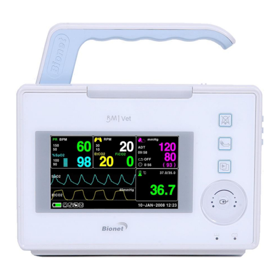
BM3 OPERATION MANUAL Product Outline BM1Vet monitor is a product used for monitoring biological vital signs of dogs and cats,.. Main functions of the product include displaying information such as SpO2, NIBP and temperature, EtCO2 on its LCD screen and monitoring parameters, and alarming. -
Page 23: Product Configuration
Warning In order to avoid electrical shock, do not open the cover. Disassembling of the equipment should be done only by the service personnel authorized by BIONET Warning Users must pay attention on connection any auxiliary device via LAN port or nurse calling. -
Page 24: Product Body Configuration
BM1VET Operation Manual Product Body Configuration Silence Alarm NIBP Go/Stop Display Mode / Home Touch Wheel Select key Battery Power LED DC Power LED BACK Output port BM1VOM-1.24 1.BASIC... - Page 25 BM1VET Operation Manual SpO2 cable Connector SpO2 IPX1 Temperature Probe IPX7 Connector NIBP Hose Connector EtCO2 Module POWER Connector ON/OFF EXT. Power USB port Output Port 5.0V NURSE Call port LAN port DC Power 2.0A Input port BM1VOM-1.24 1.BASIC...
-
Page 26: Accessories
BM1VET Operation Manual Accessories Cable + Extension Cable NIBP Cuff+ Extension cable Temperature sensor (Option) BM1VOM-1.24 1.BASIC... -
Page 27: Equipment Sign
BM1VET Operation Manual Equipment Sign ATTENTION : Consult accompanying documents TYPE CF APPLIED PART : Insulated (floating) applied part suitable for intentional external and internal application to the animal including direct cardiac application. "Paddles" outside the box indicate the applied part is defibrillator proof. - Page 28 BM1VET Operation Manual Power On/Off USB port Output port DC Power Output LAN port Nurse Call port IN OUT PORT VGA Output DC Input Indicator Battery Input Indicator DC Power Input port BM1VOM-1.24 1.BASIC...
- Page 29 BM1VET Operation Manual NIBP Temperature Pulse Rate EtCO2 / Respiration Silence Alarm Display mode selection / Home BM1VOM-1.24 1.BASIC...
-
Page 30: Function And Key
1.4 Function and Key External Function The front panel of this product consists of an LCD screen and four Touch function keys and one Touch Wheel. Operating the BM1Vet Veterinary Monitor Alarm Lamp Silence Alarm NIBP Go/Stop Display Mode /... -
Page 31: Standard Power Supply Application
BM1VET Operation Manual 1.5 Standard Power Supply Application DC Power DC Power LED is lighted on when the DC Power is plugged into the inlet at the back of the product. A press of the power key makes the machine ready for use. -
Page 32: Battery Power Supply Application
BM1VET Operation Manual 1.6 Battery Power Supply Application Battery power can be supplied for enabling portable use or for use during DC power failure. Operation 1. Battery Power LED is lighted on when the machine is in use. 2. The DC/battery power is only sustainable for 4.5 hour. - Page 33 BM1VET Operation Manual 5. The discharge condition of battery is indicated with one of 5 yellow boxes, each box showing a different level of charge available. . (100% -> 75% -> 50% -> 25% -> 0%) When the battery power remains 25%, the Low Battery icon is displayed. The power is automatically cut off after 5 minutes from the appearance of the message.
-
Page 34: The Impact Of Lithium-Ion Battery Technology On The Battery
When the battery is stored inside a monitor that is continuously powered by an AC power source and is not powered by battery on a regular basis, the life of the battery may be less than 12 months. BIONET recommends that you remove the battery and store it near the monitor until it is needed for transport. -
Page 35: Display Mode ( Monitor Or Spot )
BM1VET Operation Manual 1.7 Display Mode ( Monitor or Spot ) You can selected display mode ( Monitoring and Spot). MONITOR : Refer to the Monitor chapter of this manual for details. SPOT : Refer to the SPOT chapter of this manual for details. -
Page 36: Monitoring Mode
BM1VET Operation Manual MONITORING MODE 1. General Operation 2. Veterinary/Data Management 3. Setup 4. Trend 5. SpO2 6. NIBP 7. Temperature 8. EtCO2 Default Setting Value BM1VOM-1.24... -
Page 37: General Operation
BM1VET Operation Manual 1. General Operation 1.1 General Manu Operation Screen Composition Real Time Wave Window Parameter Windows m m Hg B PM MEDI. 09:58 Et CO2 Fi CO2 %Sp O2 ( 93 ) 0:56 42.0 ℃ Sp O2 35.0... -
Page 38: Menu Selection
BM1VET Operation Manual Menu Selection m m Hg B PM MEDI. Et CO2 Fi CO2 09:58 %Sp O2 Turn or touch ( 93 ) 0:56 the wheel. 42.0 ℃ Sp O2 35.0 36.7 40m m Hg Et CO2 A XIL L A RY 10- JA N- 2008 12:23 When the Trim Knob Key is turned, menus are selected in the order indicated above. -
Page 39: Menu Composition
BM1VET Operation Manual Menu Composition More Menu Window When the additional menu is selected it will display your available options. MAIN USER DISPLAY MENU SERVICE PREV DEMO: MAKER SOUND: MENU SERVICE Numerical value sign widow This window displays a measured parameter, function setup, and the boundary of parameter values. - Page 40 BM1VET Operation Manual Menu selection with arrows Upward Movement: Turns the touch wheel key to the left. Downward Movement: Turns the touch wheel key to the right. Selection is made by touching the touch wheel key. One exits the menu after the selection.
- Page 41 BM1VET Operation Manual Operation menu The setup value changes without a selection when the menu is moved. Change ANIMAL MAIN Animal TYPE: MENU Info HEIGHT WEIGHT PREV DEFAULT UNIT: UNIT: MENU SETTING Change ANIMAL MAIN Animal TYPE: MENU Info HEIGHT...
-
Page 42: Veterinary/Data Management
BM1VET Operation Manual 2. VETERINARY/DATA MANAGEMENT 2.1 ADMIT CHANGE ANIMAL INFO DISCHARGE HEIGHT WEIGHT 2.2 ALARM ALL LIMITS ALARM VOLUME ALARM LEVEL ALARM REVIEW ALARM LIST SAVE ALARM LEVEL NURSE CALL BM1VOM-1.24 2. VETERINARY/DATA MANAGEMENT... -
Page 43: Admit
BM1VET Operation Manual 2.1 ADMIT Additional setups are made for each parameter function. One can make an overall setup for the entire monitor system. CHANGE ANIMAL INFO : The CHANGE ANIMAL INFO option allows you to change or enter information pertinent to the monitored veterinary patient. -
Page 44: Change Animal Info
BM1VET Operation Manual CHANGE ANIMAL INFO Hospital ID(11 letters for each), animal name (11 letters for each), sex (male or female), date of birth, weight, height, and animal ID (11 characters) CHANGE ANIMAL INFORMATION > RETURN CONTENTS LAST NAME FIRST NAME... -
Page 45: Height
BM1VET Operation Manual HEIGHT Unit of height is set as Cm / Inches. CHANGE ANIMAL MAIN ANIMAL TYPE: MENU INFO HEIGHT WEIGHT PREV DEFAULT UNIT: UNIT: MENU SETTING CHANGE ANIMAL MAIN ANIMAL TYPE: MENU INFO HEIGHT WEIGHT PREV DEFAULT UNIT:... -
Page 46: Alarm
BM1VET Operation Manual 2.2 ALARM Alarm is divided into two, alarm for the animal’s condition and for the product’s condition. The animal’s alarm sound differs in order and volume according to the levels of HIGH, MEDIUM, LOW and MESSAGE. Alarm for the Product... -
Page 47: Alarm Icon
BM1VET Operation Manual ALARM LIMITS:The machine enables one to see and change the limits of alarm for all parameter functions. ALARM VOLUME:volume of each alarm can be adjusted in 10 step. ALARM LEVEL:Priority of each parameter alarm can be set up. -
Page 48: All Limits
BM1VET Operation Manual ALL LIMITS The ALL Limits menu option allows you to view the high and low alarm limits and unit of measurement for each parameter currently monitored. ALARM MAIN VOLUME: MENU LIMITS NURSE PREV ALARM ALARM CALL: MENU... -
Page 49: Alarm Volume
BM1VET Operation Manual ALARM VOLUME Set the alarm volume to be set at 10 grades. ALARM MAIN VOLUME: MENU LIMITS NURSE PREV ALARM ALARM CALL: MENU LEVEL REVIEW ALARM > MAIN VOLUME: MENU PREV 100% MENU ALARM LEVEL Set the order of priority in each alarm. -
Page 50: Parameter Level
BM1VET Operation Manual PARAMETER LEVEL PARAMETER ALARM LEVELS RETURN ALARM LEVEL SPO2-% MEDIUM SPO2-R AWRR MESSAGE EtCO2 MESSAGE FiCO2 MESSAGE APNEA MESSAGE NIBP MEDIUM TEMP MESSAGE LEAD FAULT MESSAGE PROBE OFF MESSAGE LOW BATTERY ALARM REVIEW After an alarm is triggered the alarms and data wave pattern can be reviewed. Set up for priority of each parameter alarm. -
Page 51: Alarm List
BM1VET Operation Manual ALARM LIST When an alarm activates, this shows the order of the alarms. ALARM REVIEW TIME KIND RETURN SPO2 2009/04/02 13:20:10 HIGH NIBP 2009/04/05 04:45:20 MEDIUM EtCO2 2009/04/12 15:50:15 HIGH AWRR 2009/04/15 23:20:30 ALARM REVIEW ALARM REVIEW <... -
Page 52: Save Condition
BM1VET Operation Manual SAVE CONDITION This determines the order in which triggered alarms are saved. SAVE MAIN ALARM CONDITION : MENU LIST HIGH PREV MENU SAVE MAIN ALARM CONDITION : MESSAGE MENU LIST HIGH MEDIUM PREV > HIGH MENU NURSE CALL When an alarm is triggered, this activated the NURSE CALL function. -
Page 53: Setup
BM1VET Operation Manual 3. SETUP 3.1 SETUP DISPLAY DEMO USER SERVICE MAKER SERVICE BM1VOM-1.24... -
Page 54: Setup
BM1VET Operation Manual 3.1 SETUP DISPLAY : screen set menu USER SERVICE : This is the menu to set the connection used to interface with an external computer MAKER SERVICE : This is the basic adjustment menu used to adjust the features of this product. -
Page 55: Set Date & Time
BM1VET Operation Manual SET DATE & TIME It has sub menu to set date and time. MAIN MENU PARA DATE & TIME SWEEP PREV SPEED: MENU 25mm/s SET TIME Set time of equipment. MAIN MENU TIME DATE PREV MENU MAIN... -
Page 56: Sweep Speed
BM1VET Operation Manual SWEEP SPEED Set speed of drawing wave signal pattern in this widow. MAIN MENU PARA DATE & TIME SWEEP PREV SPEED: MENU 25mm/s SWEEP MAIN SPEED: 6.25 mm/s MENU 25mm/s 12.5 mm/s > 25 mm/s PREV 50 mm/s... -
Page 57: User Service
BM1VET Operation Manual USER SERVICE The user is able to set the set UNIT NAME, BED NUMBER, external Wireless equipment power , communication parameters, and power supply filter. SET BED MAIN W-LAN: UNIT NUMBER MENU NAME : 00A DISPLAY PREV... -
Page 58: Set Bed Number
BM1VET Operation Manual SET BED NUMBER Set up for animal bed number. Allowable setters are from 0~ 9, A ~ Z . SET BED MAIN W-LAN: UNIT NUMBER MENU NAME : 00A DISPLAY PREV SYSTEM FILTER: MODE: MENU 50HZ MONITOR... -
Page 59: W-Lan
BM1VET Operation Manual W-LAN W-LAN power can be supplied for enabling an External wireless LAN equipment use. SET BED MAIN W-LAN: UNIT NUMBER MENU NAME : 00A DISPLAY PREV SYSTEM FILTER: MODE: MENU 60HZ MONITOR DISPLAY MODE ( MONITOR or SPOT ) You can selecteMonitoring display mode or Spot display mode. -
Page 60: Key Sound
BM1VET Operation Manual KEY SOUND Set ON/OFF Key Sound of equipment. MAIN USER DISPLAY MENU SERVICE PREV DEMO: MAKER SOUND: MENU SERVICE MAIN USER DISPLAY MENU SERVICE PREV DEMO: MAKER SOUND: MENU SERVICE MAKER SERVICE Maker service is a menu used by manufacturers. -
Page 61: Trend
BM1VET Operation Manual 4. TREND 4.1 TREND GRAPHIC TREND TABULAR TREND BM1VOM-1.24... -
Page 62: Trend
BM1VET Operation Manual 4.1 TREND TREND shows saved data graphically displayed with numeric values. Real-time data recording duration is 1 minute. The unit can save up to 128 hours of data. MAIN GRAPHIC TABULAR MENU TREND TREND PREV MENU : Move to main screen... -
Page 63: Graphic Trend
BM1VET Operation Manual GRAPHIC TREND Wave Data can be stored and seen according to section. MAIN GRAPHIC TABULAR MENU TREND TREND PREV MENU GRA PHIC TREND 07- A PR- 2009 13:00 Sp O2- % Sp O2- R NIB P TEMP... -
Page 64: Time Period
BM1VET Operation Manual TIME PERIOD One can set up and store data and time that one can see in a screen. GRA PHIC TREND 07- A PR- 2009 13:00 A WRR Et CO2 Fi CO2 ( 20 ) ( 38 ) -
Page 65: Tabular Trend
BM1VET Operation Manual TABULAR TREND One can see the stored data at the time previously set up. MAIN GRAPHIC TABULAR MENU TREND TREND PREV MENU TIME INTERVAL One can store data and set up time. TABULAR TREND 10- APR- 2009... -
Page 66: Spo2
BM1VET Operation Manual 5. SpO2 5.1 Outline Connector Location and Measuring Cable 5.2 SpO2 Data Window 5.3 SpO2 Data Setup SWEEP SPEED RATE VOLUME ALARM ALARM LIMIT 5.4 Trouble Shooting BM1VOM-1.24 5.SpO2... -
Page 67: Outline
BM1VET Operation Manual 5.1 Outline SPO2 monitoring is a noninvasive technique used to measure the amount of oxygenated hemoglobin and pulse rate by measuring the absorption of selected wavelengths of light. The light generated in the probe passes through the tissue and is converted into an electrical signal by the photodetector in the probe. - Page 68 When transflectance SpO2 probe is used, the preferred sensor application site for canine, feline and equine animals is in the rectal part or under the tail. WARNING Use only Bionet's reusable multisite SpO probe or transflectance SpO probe. Use of other oxygen transducers may cause improper performance.
-
Page 69: Spo2 Data Window
BM1VET Operation Manual 5.2 SpO2 Data Window %SpO , PR Alarm Limit: Indicates an %SpO ,PR alarm limit B PM Pulse Rate Beats per minute. %S pO2 Oxygen Concentration in the Strength indicators: Blood(SpO2 value) : Indicates %SpO in numbers. -
Page 70: Signal And Data Validity
BM1VET Operation Manual Signal and Data Validity It is extremely important to determine that the probe is attached to the animal correctly and the data is verifiable. To make this determination, three indications from the monitor are of assistance—signal strength bar, quality of the SPO2 waveform, and the stability of the SPO2 values. It is critical to observe all three indications simultaneously when ascertaining signal and data validity. -
Page 71: Spo2 Data Setup
BM1VET Operation Manual 5.3 SpO2 Data Setup ALARM : Menu in which SpO alarm are set up. RATE VOLUME:Menu in which RATE VOLUME is set up RATE MAIN ALARM VOLUME: MENU RATE VOLUME Move the KEY to select the volume from OFF to 100%. -
Page 72: Alarm Limit
BM1VET Operation Manual ALARM LIMIT Number setting of alarm value of %SpO 0 ~ 100 2 is 1. Move the ▶ mark to select from RETURN, SpO or SpO -R, and press. 2. After pressing at SpO , move the cursor right or left to LOW, and press. -
Page 73: Alarm Sound
BM1VET Operation Manual ALARM SOUND Warning sound or message displays configuration menu when an alarm is triggered. BM1VOM-1.24 5.SpO2... -
Page 74: Trouble Shooting
BM1VET Operation Manual 5.4 TROUBLE SHOOTING PROBE OFF Condition When using a reusable finger probe, there is a system alarm to alert you when the probe is off the Monitor. The monitor defaults this “ PROBE OFF” condition as a System Warning alarm. You can, however, set it as a System ALARM LEVEL in Monitor Defaults. -
Page 75: Nibp
BM1VET Operation Manual 6. NIBP 6.1 Outline NIBP Connector Location and Cuff 6.2 NIBP Data Window 6.3 NIBP Data Setup ALARM LIMIT ALARM CUFF SIZE UNIT SELECT INTERVAL STAT INFLATION 6.4 Trouble Shooting BM1VOM-1.24... -
Page 76: Outline
BM1VET Operation Manual 6.1 Outline This function is to measure minimum, maximum and average blood pressure by using Oscillometric method Position of NIBP Connecter and cuff NIBP Connector SpO2 IPX1 IPX7 LARGE CUFF Note As the value of NIBP can vary according to the age and sex of a animal, the user needs to set up right data in Parameter Menu before measurement. - Page 77 BM1VET Operation Manual ⚫ CAT CUFF Placement ⚫ DOG CUFF Placement BM1VOM-1.24 6. NIBP...
- Page 78 BM1VET Operation Manual Note As the value of NIBP can vary according to the age and sex of a animal, the user needs to set up right data in parameter Menu before measurement. Ensure that tubes between the cuff and the monitor are not kinked or blocked.
-
Page 79: Nibp Data Window
BM1VET Operation Manual 6.2 NIBP Data Window Cuff Type: Indicates Cuff size(Medium). Systolic pressure: Indicates the maximum limit of blood pressure display Diastolic blood pressure:Indicates the minimum limit of Measurement time blood pressure Indicates the completion time of measuring Mean Value: Indicates mean... -
Page 80: Nibp Data Setup
BM1VET Operation Manual 6.3 NIBP Data Setup ALARM: A menu to set the Alarm CUFF SIZE:A menu to select cuff size (LARGE , MEDI.(Medium) , SMALL ) UNIT SELECT: A menu to select the pressure unit (mmHg , kPa). INTERVAL :A menu to set Interval time when measures the blood pressure periodically... -
Page 81: Alarm Limit
BM1VET Operation Manual ALARM LIMIT Alarm setting Numeric Value of Systolic, Diastolic, and mean pressure is 10 ~ 300mmHg. 1. Move the ▶ mark to select one from RETURN, NIBP-S, NIBP-M, or NIBP-D, and press. 2. Press the key at NIBP-S, and move to LOW, and press again.(The user gets the same result regardless of the LOW-HIGH, or HIGH-LOW order.) -
Page 82: Alarm Sound
BM1VET Operation Manual ALARM SOUND Warning sound or message displays configuration menu when an alarm is triggered. ALARM MAIN ALARM SOUND: MENU LIMIT PREV MENU CUFF SIZE The user can select a CUF between LARGE and SMALL. CUFF MAIN ALARM... -
Page 83: Unit Select
BM1VET Operation Manual UNIT SELECT It is a function to set blood pressure measurement unit. The blood pressure measurement unit provides mmHg and kPa. CUFF MAIN ALARM SIZE: MENU MEDI. UNIT INFLATION: INTERVAL: SELECT: 170mmHg mmHg CUFF MAIN ALARM SIZE: MENU MEDI. -
Page 84: Inflation
BM1VET Operation Manual INFLATION It is a function for pressurization pressure. LARGE/MEDIUM : Numeric value is 80, 90, 100, 110, ~ 230, and 240. SMALL : Numeric value is 60, 70, 80, 90, 100, 110, and 120. CUFF MAIN ALARM... -
Page 85: Troubleshooting
BM1VET Operation Manual 6.4 TROUBLESHOOTING NIBP Status Messages Below is a list of system status alarm messages which may be displayed in the NIBP parameter window during monitoring. Status Message Monitor Response Solution System status alarm. OVER Auto mode will shut off after ONE Remove cuff and contact service. -
Page 86: Temperature
BM1VET Operation Manual 7. TEMPERATURE 7.1 Outline Temperature Connector and Measuring Cable 7.2 Temperature Data Window 7.3 Temperature Data Setup ALARM LIMIT UNIT SELECT 7.4 Trouble Shooting BM1VOM-1.24... -
Page 87: Outline
BM1VET Operation Manual 7.1 Outline This function is used to indicate the changes of resistance generated by the changes of temperature in numbers. The function involves the process of transferring the changes into electric signals. Temperature Connector and Measuring Cable... -
Page 88: Temperature Data Window
BM1VET Operation Manual 7.2 Temperature Data Window Alarm limits set for temperature : 42.0 ℃ Indicates temperature limits 35.0 Unit: Displays 36.7 Temperature: temperature unit. Displays temperature. A X I L L A R Y Note The minimum measuring time required to obtain accurate readings at the specific body site is at least 3 minutes. -
Page 89: Temperature Data Setup
BM1VET Operation Manual 7.3 Temperature Data Setup ALARM: Temperature measurement alarm set UNIT: Temperature measurement unit set UNIT MAIN ALARM SELECT: MENU °C ALARM Alarm menu provide ALARM LIMIT and ALARM SOUND. UNIT MAIN ALARM SELECT: MENU °C BM1VOM-1.24 7. Temperature... -
Page 90: Alarm Limit
BM1VET Operation Manual ALARM LIMIT Setting numeric value is 15.0℃ ~ 45.0℃. 1. Move the ▶ mark to select either RETURN or TEMP, and press. 2. After pressing the cursor at TEMP, move it to LOW, and press. 3. When the color has changed, move the cursor again to select a target value, and press. -
Page 91: Alarm Sound
BM1VET Operation Manual ALARM SOUND Warning sound or message displays configuration menu when an alarm is triggered. ALARM MAIN ALARM SOUND : MENU LIMIT PREV MENU ALARM MAIN ALARM SOUND : MENU LIMIT PREV MENU UNIT SELECT Able to select unit with °C, °F. -
Page 92: Troubleshooting
BM1VET Operation Manual 7.4 TROUBLESHOOTING Check list 1. The temperature probe(YSI 400 series) is correctly positioned on the animal 2. Temperature cable is attached to the monitor. 3. Temperature setup is adjusted, if necessary. Follow detailed procedures within this chapter. -
Page 93: Etco2
BM1VET Operation Manual 8. EtCO2 8.1 INTRODUCTION Position of EtCO Connector and Accessory EtCO ACCESSORY 8.2 EtCO Parameter Window 8.3 EtCO Parameter Setting Menu 8.4 EtCO Parameter Setting Menu 8.4 Trouble Shooting BM1VOM-1.24 8.EtCO2... -
Page 94: Introduction
BM1VET Operation Manual 8.1 Introduction ETCO2(End-Tidal CO2) is a device to see the concentration of end-tidal carbon dioxide, which uses a method of measurement based on the non-dispersed IR absorption of CO2 using IR ray by sampling a certain part of respiration through pipe during respiration. - Page 95 BM1VET Operation Manual EtCO2 accessories for sidestream applications EtCO2 monitoring accessory uses the accessories for LoFlo™ sidestream module of Respironics Company. The CO2 Sampling Cannula for sidestream Non-intubated applications 3468ADU-00 Nasal CO Sampling Cannula ADULT 3468PED-00 Nasal CO Sampling Cannula...
- Page 96 BM1VET Operation Manual The airway adapters for sidestream intubated applications 3473ADU-00 Airway Adapter Weight: 4.5 grams Deadspace – adds approximately 7 Kit w/ Dehumidification cc of deadspace Tubing Intended for use when monitoring animals with ET Tube sizes >4.0 mm...
- Page 97 BM1VET Operation Manual CAPNOSTAT 5 mainstream CO2 sensor and Mainstream sensor Mainstream sensor connector EtCO2 accessories for mainstream applications EtCO2 monitoring accessory uses the accessories for CapnoStat 5 mainstream sensor from Respironics Company. The airway adapters for mainstream intubated applications...
- Page 98 BM1VET Operation Manual Connecting the CAPNOSTAT® 5 CO2 Sensor to the Host System 1. Insert the CAPNOSTAT 5 CO Sensor connector into the receptacle of the host monitor as shown in Figure 1. 2. Make sure the arrows on the connector are at the top of the connector and line up the two keys of the connector with the receptacle and insert.
-
Page 99: Etco2 Parameter Window
BM1VET Operation Manual 8.2 EtCO2 Parameter Window AWRR AWRR Upper/lower limit value of alarm FiCO2 EtCO2 Upper/lower limit value of alarm: Display of alarm setting range value for concentration of CO EtCO : Display of concentration value of carbon dioxide... -
Page 100: Etco2 Parameter Setting Menu
BM1VET Operation Manual 8.3 EtCO2 Parameter Setting Menu ALARM: A menu to set the alarm SWEEP SPEED: Speed is changeable to 6.25, 12.5, 25mm/s. SCALE: A menu to set the screen scale of measured waveform SETUP: A menu to handle the information of EtCO2 Module ZERO : When the adapter type is changed. -
Page 101: Alarm Sound
BM1VET Operation Manual EtCO2 ALARM LIMIT RETURN UNITS HIGH EtCO2 mmHg FiCO2 mmHg AWRR APNEA The following table shows standard alarm limit of parameter and setting value of scale when setting the label. Adult Neonatal Parameter High Scale High Scale... -
Page 102: Etco2 Sweep Speed
BM1VET Operation Manual EtCO2 SWEEP SPEED EtCO2 speed is 6.5mm/s. Speed is changeable to 6.25, 12.5, 25mm/s. SWEEP MAIN ALARM SPEED: MENU > 6.25mm/s 6.25mm/s 12.5mm/s APNEA 25mm/s DETECT: WAVEFORM SCALE (Measured waveform scale setting) This sets the range of measured waveform versus pressure. -
Page 103: Setup (Various Setting)
BM1VET Operation Manual SETUP (Various setting) Different menus are applied to provide menu and information for handling the EtCO2 module. SWEEP WAVEFORM MAIN ALARM SPEED: SCALE: MENU 6.25mm/s 40mmHg APNEA DETECT: ZERO SETUP - MODULE SETUP MODULE INFO SET RETURN... - Page 104 BM1VET Operation Manual - BAROMETRIC PRESSURE: This setting is used to set current Barometric Pressure. - GAS TEMPERATURE: This setting is used to set temperature of the gas mixture. This setting is useful when bench testing using static gasses where the temperature is often room temperature or below.
- Page 105 BM1VET Operation Manual - MODULE INFORMATION MAIN MODULE MODULE MENU SETUP INFO PREV MODULE MENU RESET MODULE INFORMATION RETURN CONTENTS SENSOR PN 1022054 OEM ID SENSOR SN SN3257 HW REVISION NUM TOTAL USE TIME 1660 MIN. LAST ZERO TIME 0 MIN.
-
Page 106: Apnea Detect
BM1VET Operation Manual APNEA DETECT Turn the APNEA detection alarm off and on SWEEP WAVEFORM MAIN ALARM SPEED: SCALE: MENU 6.25mm/s 40mmHg APNEA DETECT: ZERO SETUP SWEEP WAVEFORM MAIN ALARM SPEED: SCALE: MENU 6.25mm/s 40mmHg APNEA DETECT: ZERO SETUP ZERO This function is used to initiate a Sensor zero. - Page 107 CAPNOSTAT® 5 CO2 Sensor Adapter Zero Adapter Zero 1. Set the BM1Vet to the zeroing function. 2. Connect the CAPNOSTAT 5 CO2 Sensor 3. Place the CAPNOSTAT 5 CO2 Sensor onto a clean and dry CO2 adapter that is exposed to room air and away from all sources of CO2, including the ventilator, the animal’s breath and...
- Page 108 BM1VET Operation Manual APNEA ALARM: This performs a function to set the display of apnea message alarm. This displays a “apnea” message at the center of parameter window as shown in the figure below with apnea alarm on in case of apnea until the set apnea period is passed through.
-
Page 109: Troubleshooting
BM1VET Operation Manual 8.4 TROUBLESHOOTING Following is a list of some of the message that may appear on the monitor when monitoring CO2. The message should clear when normal operating criteria are met or a solution is found. * SENSOR OVER TEMP ( “TEMP UNSTABLE”) - Cause : The sensor temperature is greater than 40’C... -
Page 110: Default Setting Value
BM1VET Operation Manual 9. DEFAULT SETTING VALUE 1. HORSE Mode Alarm level High Medium Message - Rate NIBP EtCO2 FiCO2 AWRR APNEA T( ْ ْ ْ C/ ْ ْ F) Check probe Probe Off Low Battery Parameter Limits... - Page 111 BM1VET Operation Manual LARGE Cuff Pressure 170mmHg MEDI. Cuff Pressure 140mmHg SMALL Cuff Pressure 120mmHg NIBP Limit Type Systolic NIBP Units mmHg /kPa Check Probe Message Alarm Pulse Volume EtCO2- APNEA Detect On/Off EtCO2- APNEA Message Alarm Units for Height...
-
Page 112: Dog Mode
BM1VET Operation Manual 2. DOG Mode Alarm level High Medium Message - Rate NIBP EtCO2 FiCO2 AWRR APNEA T( ْ ْ ْ C/ ْ ْ F) Check probe Probe Off Low Battery Parameter Limits High NIBP-S(mmHg) NIBP-M(mmHg) - Page 113 BM1VET Operation Manual Display Defaults Animal Type NIBP Auto NIBP Cuff Size MEDIUM LARGE Cuff Pressure 170mmHg MEDI. Cuff Pressure 140mmHg SMALL Cuff Pressure 120mmHg NIBP Limit Type Systolic NIBP Units mmHg/kPa Check Probe Message Alarm Pulse Volume EtCO2- APNEA Detect...
-
Page 114: Puppy , Cat Mode
BM1VET Operation Manual 3. PUPPY , CAT Mode Alarm level High Medium Message - Rate NIBP EtCO2 FiCO2 AWRR APNEA T( ْ ْ ْ C/ ْ ْ F) Check probe Probe Off Low Battery Parameter Limits High... - Page 115 BM1VET Operation Manual Display Defaults Animal Type Puppy , Cat NIBP Auto NIBP Cuff Size Small LARGE Cuff Pressure 170mmHg MEDI. Cuff Pressure 140mmHg SMALL Cuff Pressure 120mmHg NIBP Limit Type Systolic NIBP Units mmHg/kPa Check Probe Message Alarm Pulse Volume...
-
Page 116: Spot Mode
BM1VET Operation Manual SPOT MODE 1. General Operation 2. Veterinary/Data Management 3. Setup 4. Trend 5. SpO2 6. NIBP 7. Temperature BM1VOM-1.24... -
Page 117: General Operation
BM1VET Operation Manual 1. General Operation 1.1 Function and key The front panel of this product consists of an LCD screen and four Touch function keys and one Touch Wheel. Alarm Lamp Silence Alarm NIBP Go/Stop Display Mode / Home... -
Page 118: Screen Generating Display Mode
BM1VET Operation Manual 1.2 Screen Generating Display Mode There are 3 types of screen display modes. Select the screen display mode icon or press supplement key to change the screen display TEXT VIEW (test generating mode): Display bigger numbers on the screen. -
Page 119: Standard Menu Operation
BM1VET Operation Manual - RECORD LIST VIEW 13- SEP- 2009 15:23 UNKNOWN m m Hg 42.0 30.0 %Sp O2 MEDI. A XIL L A RY TEMP SPO2 RET PAT DATE TIME NIBP 36.7 D 09-13 12:02:02 120/80(93) P20001 UNKNOWN 09-12... -
Page 120: Menu Select
BM1VET Operation Manual 13- SEP- 2009 15:23 UNKNOWN m m Hg 42.0 30.0 %Sp O2 MEDI. A XIL L A RY TEMP SPO2 RET PAT DATE TIME NIBP 36.7 09-13 12:02:02 120/80(93) P20001 UNKNOWN 09-12 14:02:02 130/90(103) 36.8 UNKNOWN 09-12... -
Page 121: Menu Icon Composition
BM1VET Operation Manual When the Trim Knob Key is turned, Menus are selected in the order indicated above. The menus move to the right in the order of (NIBP) → (SPO2) → (TEMP) → [(RECORD LIST)] → (CANCEL) → (SAVE) → (VIEWER MODE ) → (SETUP) → (ALARM) → (ANIMAL) -
Page 122: Select Menu Using By Touch Wheel Key
BM1VET Operation Manual Select Menu Using by Touch wheel Key A right-hand turn makes a movement in a clockwise direction. A left-hand turn makes a movement in an anti-clockwise direction. A selection is made by touching the center of touch Wheel Key. -
Page 123: Letter Arrangement Menu
BM1VET Operation Manual Letter Arrangement Menu The following figure shows the screen where the word sequence menu is activated within the word sequence correction menu. Here, the cursor moves over the words when the touch wheel Key is turned in the clockwise direction. -
Page 124: List Selective Menu
BM1VET Operation Manual List selective menu Whenever the square moves, a selected letter or a number is highlighted displaying its value. Operation Menu The set up value changes without a selection when the menu is moved. SWEEP MAIN SPEED: MENU... -
Page 125: Veterinary/Data Management
BM1VET Operation Manual 2. VETERINARY/DATA MANAGEMENT 2.1 Outline 2.2 Animal Type 2.3 Select ANIMAL in Admit Information 2.4 Alarm Outline 2.5 Alarm Setup 2.6 Alarm Limit Setup 2.7 Alarm Volume 2.8 Alarm Level 2.9 Nurse Call 2.10 Alarm Sound BM1VOM-1.24... -
Page 126: Outline
BM1VET Operation Manual 2.1 Outline Resister Animal’s ID and name to save data of each animal. Divide to Animal’s ID and type. Animal’s type divided as horse, dog, puppy, and cat. The screen initializes after once saved animal’s record in Spot mode. - Page 127 BM1VET Operation Manual Select TYPE of menu in the menu window and register type of animal. ANIMAL MAIN ANIMAL ID TYPE: > HORSE MENU HORSE PUPPY PREV MENU Select save menu and complete animal registration. Display registered animal’s ID and Type on the top of the screen.
-
Page 128: Select Animal In Admit Information
BM1VET Operation Manual 2.3 Select Animal in Admit Information Select animal icon in menu icon. Select search menu and Confirm animal list in menu window. The animal list is the animal who already has measured data. ANIMAL MAIN TYPE: SAVE... -
Page 129: Alarm Outline
BM1VET Operation Manual 2.4 Alarm Outline Alarm is divided into two, alarm for the animal’s condition and for the product’s condition. The animal’s alarm sound differs in order in order and volume according to the levels of HIGH, MEDIUM, LOW and MESSAGE. -
Page 130: Alarm Setup
BM1VET Operation Manual 2.5 Alarm Setup Select alarm icon in menu icon. ALARM MAIN ALARM VOLUME: MENU LIMIT NURSE ALARM ALARM CALL: SOUND LEVEL ALARM LIMITS:The machine enables one to see and change the limits of alarm for all parameter functions. -
Page 131: Alarm Volume
BM1VET Operation Manual 2.7 Alarm Volume The volume of each alarm can be adjusted in 10 steps. ALARM MAIN ALARM VOLUME: MENU LIMIT NURSE ALARM ALARM CALL: SOUND LEVEL ALARM >OFF MAIN VOLUME: MENU PREV 100% MENU 2.8 Alarm Level Priority of each parameter alarm can be set up. -
Page 132: Nurse Call
BM1VET Operation Manual 2.9 Nurse Call Set the ON/OFF feature of the NURSE CALL. ALARM MAIN ALARM VOLUME: MENU LIMIT NURSE ALARM ALARM CALL: SOUND LEVEL 2.10 Alarm Sound Set the ON/OFF feature of the Alarm Sound ALARM MAIN ALARM... -
Page 133: Save Record
BM1VET Operation Manual 3. SAVE RECORD 3.1 Outline 3.2 Adjust to Record Mode 3.3 Measure with Monitor Mode 3.3 Measure with Spot Mode 3.4 Save 3.5 Exit from Saving Mode BM1VOM-1.24... -
Page 134: Outline
BM1VET Operation Manual 3.1 Outline There are two modes to save data. One is called MONITOR mode. It saves the animal’s ID/TYPE without re-register once animal registered. The other called SPOT mode. It initializes the machine once animal’s record saved. -
Page 135: Measure With Spot Mode
BM1VET Operation Manual 3.4 Measure with Spot Mode Measure after setup a mode to MANUAL. SAVE MAIN USER DISPLAY MODE: MENU SERVICE MANUAL MAKER SOUND: SYSTEM SERVICE It saves as press the button after measurement. NIBP ending spot numeric value stores when NIBP is INTERVAL mode. -
Page 136: Save
BM1VET Operation Manual 3.5 Save It can be saved automatically by the user not only by MANUAL or AUTO mode. Select save button in the menu button. 10- SEP- 2009 15:23 ABC1234 m m Hg 200 / 80 150/ 50 42.0... -
Page 137: Saved Data Management
BM1VET Operation Manual 4. SAVED DATA MANAGEMENT 4.1 Record List View 4.2 Exit from Record List 4.3 View Specified Animal Record List 4.4 View All Animals Record List 4.5 Adjust Record 4.6 Delete a Record 4.7 Delete an Animal’s Record 4.8 Delete All Animal’s Record... -
Page 138: Record List View
BM1VET Operation Manual 4.1 Record List View Set up Record List View after selecting print mode icon of menu icon. Select in the List window and move inside of the list for Management. Turn touch wheel button inside of the list then move to records. - Page 139 BM1VET Operation Manual 2. Press return menu at the top of the record list window. 13- SEP- 2009 15:23 UNKNOWN m m Hg 42.0 30.0 %Sp O2 MEDI. A XIL L A RY SPO2 TEMP RET PAT DATE TIME NIBP 36.7...
-
Page 140: View Specified Animal's Record List
BM1VET Operation Manual 4.3 View Specified Animal’s Record List Move to Record List window to view an animal’s Record List. Move to an animal’s record by turning touch wheel button. 13- SEP- 2009 15:23 UNKNOWN m m Hg 42.0 30.0 36.5... -
Page 141: View All Animal's Record List
BM1VET Operation Manual 4.4 View All Animal’s Record List Move to Record List. Touch Key on Animal’s record in the list then Menu window will pop up. Select View All menu in Menu window. 13- SEP- 2009 15:23 UNKNOWN m m Hg 42.0... -
Page 142: Adjust Record
BM1VET Operation Manual 4.5 Adjust Record Move to Record List to adjust the record. Move to the Record which you want to adjust by turning touch wheel Key. Select Edit menu in the list. 13- SEP- 2009 15:23 UNKNOWN m m Hg 42.0... - Page 143 BM1VET Operation Manual 2) Adjust animal’s type. Select Type menu and Adjust TYPE SAVE CANCEL TYPE > HORSE PUPPY Alarm status will not be changed as a result of excess alarm limit at the moment of measurement even though animal type changed results in alarm limit numeric value change. Select SAVE menu to save changed status.
-
Page 144: Delete A Record
BM1VET Operation Manual 4.6 Delete a Record Move to the Record List. Move to the Record where you want to adjust by turning touch wheel Key. Be cautious to delete because deleted record can not be undeleted. 13- SEP- 2009 15:23... -
Page 145: Delete An Animal's Record
BM1VET Operation Manual 4.7 Delete an Animal’s Record Move to record list in order to delete the record. Move to the Record where you want to adjust by turning touch wheel Key. Touch Key in the list and menu will pop up then select Delete Animal button. -
Page 146: Delete All Animals' Record
BM1VET Operation Manual 4.8 Delete All Animals’ Record Enter the record list to delete all the record. Select touch wheel Button in the animal’s record then select Delete All. Be cautious to delete because deleted record can not be undeleted. -
Page 147: Setup
BM1VET Operation Manual 5. SETUP 5.1 SETUP 5.2 DISPLAY 5.3 MODE 5.4 USER SERVICE 5.5 SYSTEM 5.6 KEY SOUND 5.7 MAKER SERVICE BM1VOM-1.24... -
Page 148: Setup
BM1VET Operation Manual 5.1 SETUP Select setup Icon in the menu icon. DISPLAY: A menu to set up screen SAVE MODE: A menu to setup the record saving mode USER SERVICE: To setup information of equipment SYSTEM: To set up connection to external computer KEY SOUND: Set up ON/OFF of Key sound. -
Page 149: Display
BM1VET Operation Manual 5.2. DISPLAY SWEEP MAIN SPEED: MENU DATE TIME 25mm/s PREV DEMO: MENU 1. SWEEP SPEED Set up print speed of amount of oxygen in the blood (SPO2) wave pattern. 2. SET DATE Setup and adjust the date. - Page 150 BM1VET Operation Manual 3. SET TIME Setup and adjust the time. SWEEP MAIN SPEED: MENU DATE TIME 25mm/s PREV DEMO: MENU MAIN MENU TIME: 10 : 58 : 01 PREV MENU 4. DEMO Setup the movement to demo/action mode. SWEEP...
-
Page 151: Save Mode
BM1VET Operation Manual 5.3 SAVE MODE Set up menu for record saving mode. SAVE MAIN USER DISPLAY MODE: MENU SERVICE AUTO MAKER SOUND: SYSTEM SERVICE SAVE MAIN USER DISPLAY MODE: MENU SERVICE MANUAL MAKER SOUND: SYSTEM SERVICE Monitor mode is to save all measured data with a same patient ID and TYPE. - Page 152 BM1VET Operation Manual 1. UNIT NAME Set up UNIT name for connected hospital with equipment. SET BED DISPLAY MAIN UNIT NUMBER MODE: MENU NAME : 00A SPOT PREV MENU MAIN UNIT MENU NAME █ PREV MENU 2. SET BED NUMBER Setup the number for the bed which connected to the equipment.
-
Page 153: System
BM1VET Operation Manual 5.5 SYSTEM Setup for connect to outside computer. SAVE MAIN USER DISPLAY MODE: MENU SERVICE AUTO MAKER SOUND: SYSTEM SERVICE SYSTEM INFO SET RETURN CONTENTS MAIN VER 1.00.BHCDDC00A CENTRAL HOST IP 192 . 168 . 030 . 077 DEVICE IP 192 . -
Page 154: Key Sound
BM1VET Operation Manual 5.6 KEY SOUND Setup ON/OFF of key sound. SAVE MAIN USER DISPLAY MODE: MENU SERVICE AUTO MAKER SOUND: SYSTEM SERVICE SAVE MAIN USER DISPLAY MODE: MENU SERVICE AUTO MAKER SOUND: SYSTEM SERVICE 5.7 MAKER SERVICE A menu used by the manufacturer of the product. -
Page 155: Nibp
BM1VET Operation Manual 6. NIBP 6.1 Outline NIBP Connector Location and Cuff 6.2 NIBP Data Window 6.3 NIBP Data Setup ALARM LIMIT CUFF SIZE UNIT SELECT INTERVAL INFLATION 6.4 Trouble Shooting BM1VOM-1.24... -
Page 156: Outline
BM1VET Operation Manual 6.1 Outline The function is to measure minimum, maximum, and average blood pressure by using oscillometric method. NIBP Connector Location and Cuff NIBP Connector SpO2 IPX1 IPX7 ADULT NIBP CUFF BM1VOM-1.24 6.NIBP... - Page 157 BM1VET Operation Manual Note As the value of NIBP can vary according to the age and sex of an animal, the user needs to set up right data in Parameter Menu before measurement. The NIBP cable connector is insulated and it is defibrillator-proof( ).
-
Page 158: Nibp Data Window
BM1VET Operation Manual 6.2 NIBP Data Window Alarm limit numeric value: display alarm setting range of blood pressure Cuff Type:Indicates Cuff size(Adult). Systolic pressure: Indicates the maximum limit of blood pressure display Diastolic blood pressure:Indicates the minimum limit of blood pressure Mean Value:... -
Page 159: Nibp Data Setup
BM1VET Operation Manual 6.3 NIBP Data Setup ALARM: A menu to set the Alarm CUFF SIZE:A menu to select cuff size ( LARGE(HORSE) , MEDI.(DOG) , SMALL(PUPPY,CAT) ) UNIT SELECT: A menu to select the pressure unit (mmHg , kPa). -
Page 160: Cuff Size
BM1VET Operation Manual CUFF SIZE The user can select a CUFF between LARGE and SMALL. CUFF MAIN ALARM SIZE: MENU LIMIT MEDI. UNIT INTERVAL: INFLATION: SELECT: 170mmHg mmHg CUFF MAIN ALARM SIZE: MENU LIMIT > LARGE MEDI. MEDI. SMALL INTERVAL: UNIT SELECT It is a function to set blood pressure measurement unit. -
Page 161: Inflation
BM1VET Operation Manual INFLATION It is a function for pressurization value. LARGE/MEDI. : Numeric value is 80, 90, 100, 110, ~ 230, and 240. SMALL : Numeric value is 60, 70, 80, 90, 100, 110, and 120. CUFF MAIN ALARM... -
Page 162: Interval
BM1VET Operation Manual INTERVAL This menu is used for selecting intervals when measures the blood pressure automatically. Select a target interval from 1min, 2, 3, 4, 5, 10, 15, 20, 30, 1hour, 2, 4, 8. CUFF MAIN ALARM SIZE: MENU LIMIT MEDI. -
Page 163: Troubleshooting
BM1VET Operation Manual 6.4 TROUBLESHOOTING NIBP Status Messages Below is a list of system status alarm messages which may be displayed in the NIBP parameter window during monitoring. Status Message Monitor Pesponse Solution System status alarm. OVER Auto mode will shut off after ONE Remove cuff and contact service. -
Page 164: Spo
BM1VET Operation Manual 7. SpO 7.1 Outline Connector Location and Measuring Cable 7.2 SpO2 Data Window 7.3 SpO2 Data Setup ALARM LIMIT SWEEP SPEED RATE VOLUME 7.4 Trouble Shooting BM1VOM-1.24... -
Page 165: Outline
BM1VET Operation Manual 7.1 Outline SPO2 monitoring is a noninvasive technique used to measure the amount of oxygenated hemoglobin and pulse rate by measuring the absorption of selected wavelengths of light. The light generated in the probe passes through the tissue and is converted into an electrical signal by the photodetector in the probe. - Page 166 BM1VET Operation Manual ⚫ Position of SpO Probe Note The signal input is a high-insulation port and it is defibrillator proof ( The insulated input ensures animal safety and protects the device during defibrillation and electrosurgery. BM1VOM-1.24 7.SpO2...
-
Page 167: Spo2 Data Window
BM1VET Operation Manual 7.2 SpO2 Data Window PR Alarm Limit: Indicates an PR Pulse Rate Beats per minute. %SpO Alarm Limit: Indicates an %SpO Oxygen Concentration in the Blood(SpO2 value) Strength indicators: : Indicates %SpO in numbers. Indicates SpO Strength in a bar graph. -
Page 168: Spo2 Data Setup
BM1VET Operation Manual 7.3 SpO2 Data Setup ALARM LIMIT:A menu to set SpO limit. SWEEP SPEED: A menu to set speed of WAVE display. RATE VOLUME: A menu to set Rate Volume. PR SOURCE: A menu to set PR source measurement. -
Page 169: Sweep Speed
BM1VET Operation Manual SWEEP SPEED Adjust WAVE DISPLAY speed setup as below. Numeric value is 6.25, 12.5, 25, 50mm/s SWEEP RATE MAIN ALARM SPEED: VOLUME: MENU LIMIT 25mm/s SOURCE: SPO2 SWEEP MAIN ALARM SPEED: 6.25 mm/s MENU LIMIT 25mm/s 12.5 mm/s >... -
Page 170: Trouble Shooting
BM1VET Operation Manual 7.4 TROUBLE SHOOTING PROBE OFF Condition When using a reusable probe, there is a system alarm to alert you when the probe is off the Monitor. The monitor defaults this “ PROBE OFF” condition as a System Warning alarm. You can, however, set it as a System ALARM LEVEL in Monitor Defaults. -
Page 171: Temperature
BM1VET Operation Manual 8. TEMPERATURE 8.1 Outline Temperature Connector and Measuring Cable 8.2 Temperature Data Window 8.3 Temperature Data Setup 8.4 Trouble Shooting BM1VOM-1.24... -
Page 172: Outline
BM1VET Operation Manual 8.1 Outline This function is used to indicate the changes of resistance generated by the changes of temperature in numbers. The function involves the process of transferring the changes into electric signals. Temperature Connector and Measuring Cable... -
Page 173: Temperature Data Window
BM1VET Operation Manual 8.2 Temperature Data Window 42.0 Alarm limit on the least low ℃ 35.0 temperature : Indicates temperature limits Unit: Displays 36.7 temperature unit. Temperature: Displays temperature. A X I L L A R Y Note The minimum measuring time required to obtain accurate readings at the specific body site is at least 3 minutes. -
Page 174: Temperature Data Setup
BM1VET Operation Manual 8.3 Temperature Data Setup ALARM LIMIT: Sets up temperature limit. TEMP MODE: Displays method of temperature measurement. PROBE SITE: Displays temperature measurement region. UNIT: Sets up temperature measurement unit. ALARM LIMIT Numeric value is 15.0℃ ~ 45.0℃. -
Page 175: Probe Site (Measurement Position)
BM1VET Operation Manual PROBE SITE (Measurement Position) Set up to display temperature measurement region. Measurement regions are ORAL, AUXILLARY, and RECTAL. UNIT SELECT Able to select unit with °C, °F. BM1VOM-1.24 8.TEMPERATURE... -
Page 176: Troubleshooting
BM1VET Operation Manual 8.4 TROUBLESHOOTING Check list 4. The temperature probe(YSI 400 series) is correctly positioned on the animal. 5. Temperature cable is attached to the monitor. 6. Temperature setup is adjusted, if necessary. Follow detailed procedures within this chapter. -
Page 177: Default Setting Value
BM1VET Operation Manual 9. DEFAULT SETTING VALUE 1. HORSE Mode Alarm level High Medium Message - Rate NIBP T( ْ ْ ْ C/ ْ ْ F) Check probe Probe Off Low Battery Parameter Limits High NIBP-S(mmHg) NIBP-M(mmHg) -
Page 178: Dog Mode
BM1VET Operation Manual 2. DOG Mode Alarm level High Medium Message - Rate NIBP T( ْ ْ ْ C/ ْ ْ F) Check probe Probe Off Low Battery Parameter Limits High NIBP-S(mmHg) NIBP-M(mmHg) NIBP-D(mmHg) - Rate T( ْ ْ ْ C/ ْ ْ ْ F ) 36.0 ℃... -
Page 179: Puppy , Cat Mode
BM1VET Operation Manual 3. PUPPY , CAT Mode Alarm level High Medium Message - Rate NIBP T( ْ ْ ْ C/ ْ ْ F) Check probe Probe Off Low Battery Parameter Limits High NIBP-S(mmHg) NIBP-M(mmHg) NIBP-D(mmHg) - Rate T( ْ... -
Page 180: Specification
BM1VET Operation Manual 10. SPECIFICATION Ease of use Customization Special Features Monitor Environmental Specifications Power adaptor Monitor Performance Specifications Graphical and Tabular Trends SpO2 Performance Specifications NIBP Performance Specifications Temperature Unit Performance Specifications EtCO2 Performance Specifications Accessories included OPTION BM1VOM-1.24... -
Page 181: Ease Of Use
BM1VET Operation Manual Ease of use · Battery operation · Table and graphic trend · Nellcor SpO Sensor interchanges Additional Function · LAN Connection · Nurse Call Monitor Environmental Specifications · Operating Temperature: 15°C to 30°C (59°F to 86°F) · Storage Temperature: - 10°C to 60°C (14°F to 140°F) ·... -
Page 182: Spo 2 Capacity
BM1VET Operation Manual capacity · Saturation Range: 0% to 100% oxygen proportion · Pulse Rate Range: 30 to 254 bpm · SpO accuracy: 70% to 100% ±2 digits, 0% to 69% unspecified · pulse accuracy: ±2 bpm · Sensor Red 660nm, 2mW (typical) Infrared 905nm, 2-2.4mW (typical) - Page 183 BM1VET Operation Manual Appendix A. Electromagnetic Emissions and Immunity Manufacturer’s declaration - electromagnetic emission The BM1 system is intended for use in the electromagnetic environment specified below. The customer or the user of BM1 system should assure that it is used in such an environment...
- Page 184 BM1VET Operation Manual Voltage dips, <5% Uт (>95% dip in Uт) <5% Uт (>95% dip in Uт) Mains power quality short for 0.5cycle for 0.5cycle should be that of a Interruptions and typical commercial or 40% Uт (60% dip in Uт ) 40% Uт...
- Page 185 BM1VET Operation Manual Radiated RF 3 V/m 3 V/m Recommended separation distance IEC 61000-4-3 80.0 MHz to 2.5 80.0 MHz to 2.5 Where P is the maximum output power rating of the transmitter in watts (W) according to the transmitter manufacturer and d is the recommended separation distance in meters (m).
- Page 186 BM1VET Operation Manual 11.70 11.70 23.30 For transmitters rated at a maximum output power not listed above, the recommended separation distance (d) in meters (m) can be estimated using the equation applicable to the frequency of the transmitter, where P is the maximum output power rating of the transmitter in watts (W) according to the transmitter manufacturer.
- Page 187 BM1VET Operation Manual Guidance and manufacturer’s declaration - electromagnetic immunity The BM1 system is intended for use in the electromagnetic environment specified below. The customer or the user of the BM1 system should assure that it is used in such an...
-
Page 188: Abbreviations And Symbols
BM1VET Operation Manual Abbreviations and Symbols Abbreviations and symbols which you may encounter while reading this manual or using the monitor are listed below with their meanings. Abbreviations amps alternating current adult Auto, AUTO automatic Auxiliary beats per minute Celsius... - Page 189 BM1VET Operation Manual M mean, minute meter MIN, min minute MM, mm millimeters MM/S millimeters per second MMHG, mmHg millimeters of mercury millivolt NIBP noninvasive blood pressure NEO, Neo neonatal pediatric RESP respiration respiration rate systolic second SpO2 arterial oxygen saturation from pulse oximetry...
-
Page 190: Product Warranty
BM1VET Operation Manual PRODUCT WARRANTY Product Name Veterinary Monitor Model Name BM1 VET Approval Number Approval Date Serial Number Warranty Period 4 years from date of purchase Date of Purchase Hospital Name : Customer Address : Section Name : Phone :... - Page 191 BM1VET Operation Manual International Sales & service Bionet Co., Ltd. : 5F, Shinsegae I&C Digital Center 61 Digital-ro 31 gil, Guro-gu, SEOUL 08375, REPUBLIC OF KOREA Tel : +82-2-6300-6410 / Fax : +82-2-6499-7789 / e-mail: sales@ebionet.com Website: www.ebionet.com U.S.A sales & service representative Bionet America, Inc.
Need help?
Do you have a question about the BM1VET and is the answer not in the manual?
Questions and answers