Table of Contents
Advertisement
Quick Links
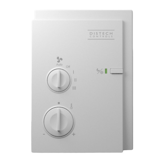
Allure EC-Sensor Series
Figure 1:
EC-Sensor-SOF
Product Description
The Allure EC-Sensor series of analog wall sensors is designed to interface with controllers of fan coil, heat pump, roof top and terminal heating / cooling
units. These sensors provide precision local temperature measurement with the capability of local setpoint adjustment, fan speed setting, and occupancy
override.
Each sensor in this series has internal communications terminals to connect it to a LON
exists, allowing a user to connect a computer to the communication network without having to open the sensor's cover. In addition, through this commu-
nication jack, an EC-Smart-Sensor-VAV can be used as a hand-held balancing tool to perform VAV airflow calibration.
The EC-Sensor's modern, alluring profile enclosure is suitable for classrooms, hotels, executive areas, office spaces and other commercial areas.
Mounting hardware with a separate sub-base is provided with the device for installation on a dry wall or on an electrical junction box.
This document describes the hardware installation procedures for the following device models: EC-Sensor, EC-Sensor-O, EC-Sensor-S, EC-Sensor-SO,
and EC-Sensor-SOF.
Unless otherwise indicated, the term EC-Sensor will be used in this document to represent all the models of the
Allure EC-Sensor Series.
For proper installation and subsequent operation of the device, pay special attention to the following recommendations:
£
Upon unpacking, inspect the contents of the carton for shipping damages. Do not install a damaged device.
£
Allow for proper clearance around the device's enclosure and wiring terminals to provide easy access for hardware configuration and maintenance.
£
Orient the device with the ventilation slots towards the top to permit proper heat dissipation.
£
The device is designed to operate under the following environmental conditions:
– Operating temperature from 32°F to 122°F (0°C to 50°C)
– Storage temperature from 4°F to 158°F (-20°C to 70°C)
– Relative humidity from 0% to 90%, non-condensing.
£
Ensure proper ventilation of the device and avoid areas where corroding, deteriorating or explosive vapors, fumes or gases may be present.
Any type of modification to any Distech Controls product will void the product's warranty
Take reasonable precautions to prevent electrostatic discharge to the device when installing, servicing or during operation. Discharge
accumulated static electricity by touching one's hand to a well-grounded object before working with the device.
H a r d w a r e I n s t a l l a t i o n G u i d e
®
®
or BACnet
network. In addition, a built-in communications jack
Advertisement
Table of Contents

Subscribe to Our Youtube Channel
Summary of Contents for Distech Controls Allure EC-Sensor Series
- Page 1 Product Description The Allure EC-Sensor series of analog wall sensors is designed to interface with controllers of fan coil, heat pump, roof top and terminal heating / cooling units. These sensors provide precision local temperature measurement with the capability of local setpoint adjustment, fan speed setting, and occupancy override.
- Page 2 General Wiring Recommendations Risk of Electric Shock: Turn off power before any kind of servicing to avoid electric shock. £ All wiring must comply with electrical wiring diagrams as well as national and local electrical codes. £ To connect the wiring to a device, use the terminal connectors. Use a small flat screwdriver to tighten the terminal connector screws once the wires have been inserted (strip length: 0.25’’...
- Page 3 Device Mounting Wall anchors ß To temperature sensor Security screw Figure 2: Mounting a sensor Device Dimensions Dimensions = mm (Inches) Figure 3: From top left to bottom: Front view, back plate, side view Device Wiring The EC-Sensor has physical connections for up to four (4) different features depending on the model. These features include the following: £...
- Page 4 Wiring the 10kΩ Thermistor Terminals TEMP and COMMON are used for the 10kΩ type 2 NTC thermistor, as well as for the override button (not available on EC-Sensor and EC- Sensor-S models). These two terminals are present on every EC-Sensor model. Internal NTC Thermistor 10kΩ...
- Page 5 Internal resistors 5-position rotary 2.5kΩ switch Controller 5.0kΩ FANSPEED COMMON 7.5kΩ 10.0kΩ Figure 7: Five-position fan speed input Wiring a EC-Smart-Sensor to a VAV for Air Flow Balancing (LON controllers only) The communications terminals (NET+ and NET-) within the EC-Sensor can be connected to the SMRT+ and SMRT- inputs of a VAV and facilitate VAV balancing with an EC-Smart-Sensor-VAV.
- Page 6 22AWG (0.65mm) unshielded Controller twisted pair network cable Bus-topology network <10ft (3m) Sensor Figure 9: Network Bus Topology with T-tap ORKS To wire a laptop to the L network with T-tap via an EC-Sensor, do the following: ORKS 1. Remove the front plate of the EC-Sensor. 2.
- Page 7 To wire a laptop to a bus topology L network via an EC-Sensor, do the following: ORKS 1. Remove the front plate of the EC-Sensor. 2. Connect the LON cables coming from the previous device and going to the EC-Sensor to the LON1 and LON2 input terminals on the controller. If in- serting multiple wires in the terminals, ensure to properly twist wires together prior to inserting them in the terminal connectors.
- Page 8 ©, Distech Controls Inc., 2010 - 2020. All rights reserved. Images are simulated. While all efforts have been made to verify the accuracy of information in this manual, Distech Controls is not responsible for damages or claims arising from the use of this manual.


Need help?
Do you have a question about the Allure EC-Sensor Series and is the answer not in the manual?
Questions and answers