Advertisement
Quick Links
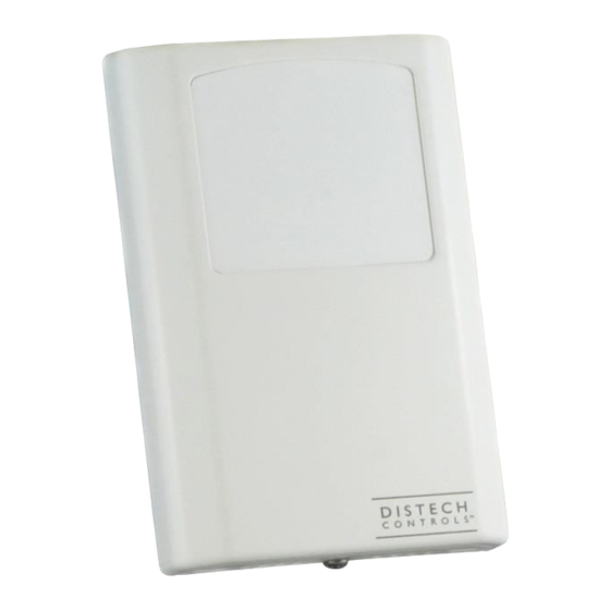
GS-AQR
Indoor Air Quality Sensor
Figure 1: GS-AQR Indoor Air Quality Sensor
Product Description
This document describes the hardware installation procedures for the
GS-AQR Indoor Air Quality Sensor
The Indoor Air Quality Sensor uses an advanced MEMS metal oxide
semiconductor sensor to detect poor air quality. The sensor reacts
quickly to detect a broad range of VOCs such as smoke, cooking
odors, bio-effluence, outdoor pollutants and from human activities. The
sensor captures all VOC emissions that are completely invisible to CO
sensors.
General Installation Requirements
For proper installation and subsequent operation of each device, pay
special attention to the following recommendations:
-
Upon unpacking the product, inspect the contents of the carton for
shipping damages. Do not install damaged device.
-
Avoid areas where corroding, deteriorating or explosive vapors,
fumes or gases may be present.
-
Ensure that all equipment is installed according to local, regional,
and national regulations.
Personal injury or loss of life may occur if you do not follow a
procedure as specified.
Equipment damage or loss of data may occur if you do not
follow a procedure as specified.
Take reasonable precautions to prevent electrostatic
discharges to the controller when installing, servicing or
operating the controller. Discharge accumulated static
electricity by touching one's hand to a well-grounded object
before working with the controller.
H a r d w a r e I n s t a l l a t i o n G u i d e
Mounting Instructions
The GS-AQR Series room sensor will install directly on a standard
electrical box and should be mounted about five feet from the floor of
the area to be controlled. For best operation, do not mount the sensor
near doors, opening windows, supply air diffusers or other known air
disturbances. Avoid areas where the detector is exposed to vibrations
or rapid temperature changes.
2
1.
The cover is hooked to the base at the top edge and must be
removed from the bottom edge first. Use a small Phillips
screwdriver to loosen the security screw as shown in Figure 2.
(Complete removal of this screw is not required).
Figure 2: Loosen security screw.
Advertisement

Related Manuals for Distech Controls GS-AQR


Summary of Contents for Distech Controls GS-AQR
- Page 1 Mounting Instructions This document describes the hardware installation procedures for the The GS-AQR Series room sensor will install directly on a standard GS-AQR Indoor Air Quality Sensor electrical box and should be mounted about five feet from the floor of The Indoor Air Quality Sensor uses an advanced MEMS metal oxide the area to be controlled.
- Page 2 Use the screwdriver to carefully pry each bottom corner if necessary. Tip the cover away from the base and place it aside as shown Figure 3. Figure 6: Snap PCB onto baseplate. Make wire connections as per the Wiring and install decorative Figure 3: Remove faceplate.
-
Page 3: Operation
secondary of an AC transformer or when wiring multiple devices to Various thermistors or RTDs may be installed on the pcb to suit the ensure that the circuit ground point is the same on all devices and the application. These terminals would connect to a thermistor or RTD controller. - Page 4 Table 1: Linear output scaling. Table 2: ASO operation. If the device is equipped with the optional relay, then the normally open relay will close when the air quality exceeds a pre-set trip point. The trip point and hysteresis value can be programmed via the menu such that the relay closes when IAQ >...
- Page 5 Setup The menu may be accessed any time after the initial warm-up period. The menu is controlled by using the three buttons on the PCB labeled UP, DOWN and MENU. All values entered are saved in non-volatile memory and will be restored correctly in case of a power failure. The menu has several items as shown below.
- Page 6 8. Backlite On/Off The LCD backlight is normally on, it can be turned off here. Backlite Press <MENU> to advance. Use <UP> or <DOWN> to add or subtract an offset to the IAQ signal. This can change from -200 to + 200 ppm 9.
- Page 7 Dimensions Figure 14: Dimensions and mounting hole locations.
- Page 8 ©, Distech Controls Inc., 2016. All rights reserved. While all efforts have been made to verify the accuracy of information in this manual, Distech Controls is not responsible for damages or claims arising from the use of this manual. Persons using this manual are assumed to be trained HVAC specialist / installers and are responsible for using the correct wiring procedures and maintaining safe working conditions with fail-safe environments.
Need help?
Do you have a question about the GS-AQR and is the answer not in the manual?
Questions and answers