
Related Manuals for Endress+Hauser Memograph CVM40


Summary of Contents for Endress+Hauser Memograph CVM40
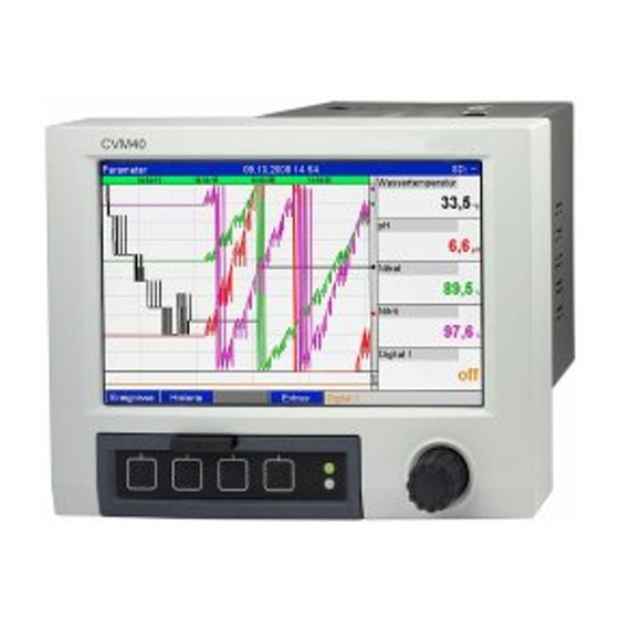
- Page 1 Brief Operating Instructions Memograph CVM40 Graphic transmitter for inline photometers and data manager KA457C/07/EN/13.10 71128660...
-
Page 3: Table Of Contents
Memograph CVM40 Table of contents Safety instructions ..4 Designated use ..... . 4 Installation, commissioning and operation . -
Page 4: Safety Instructions
Safety instructions Memograph CVM40 Safety instructions Designated use This unit is designed for operating inline photometers for UV, color, NIR, turbidity and cell growth. Furthermore it can be used for the electronic acquisition, display, recording, analysis, remote transmission and archiving of analog and digital input signals in non-hazardous areas. -
Page 5: Return
Memograph CVM40 Safety instructions Return If the device has to be repaired, please return it cleaned to the sales center responsible. Please use the original packaging, if possible. Notes on safety icons and symbols Safety icons Warning! This symbol alerts you to hazards that can cause serious damage to the instrument or to persons if ignored. -
Page 6: Identification
Identification Memograph CVM40 Identification Scope of delivery The scope of delivery comprises: • Device (with terminals, as per your order) • 2 fastening clips • USB interface cable, length 1.5 m (4.9 ft) • Optional secure digital (SD) card • Link to PC operating and configuration software on CD-ROM •... -
Page 7: Installation
Memograph CVM40 Installation Installation Measuring system A complete measuring system comprises: • Memograph CVM40 • An optical sensor, e.g. OUSAF44 • Flow assembly, e.g. OUA260 • Cable set, e.g. OUK40 a0012117 Fig. 1: Example of a measuring system Cable set OUK40... -
Page 8: Installation Conditions
Installation Memograph CVM40 Installation conditions Working temperature range: -10 to 50 °C (14 to 122 °F), max. 75% rel. humidity without condensation. " Caution! • To avoid heat accumulation, please always ensure that the unit is sufficiently cooled. • Maintain distance from strong magnetic fields (see Operating Instructions on CD-ROM, Section 10 "Technical data", interference immunity) -
Page 9: Installation Instructions
Memograph CVM40 Installation Installation instructions 3.3.1 Mounting the device Panel cutout and installation / design, dimensions 216.03 (8.51) 199.2 (7.84) 137.5 (5.41) (1.14) 136 (5.35) 39.07 (1.54) 195.23 (7.69) 196.2 (7.72) 58.2 (2.29) 138 (5.43) mm (inch) a0012075 Fig. 2: Dimensions / panel cutout... - Page 10 Installation Memograph CVM40 Mounting dimensions: • Installation depth: approx. 216 mm (8.51") (incl. terminals) +0.04 +0.04 • Panel cutout: 138 x 138 mm (5.43 x 5.43 ") • Panel thickness: 2 to 40 mm (0.08 to 1.58") • Max. viewing angle range: from the central display axis 50° in all directions •...
-
Page 11: Wiring
Memograph CVM40 Wiring Wiring Electrical connection Warning! • The electrical connection must only be carried out by a certified electrician. • Technical personnel must have read and understood the instructions in this manual and must adhere to them. • Ensure that there is no voltage at the power cable before beginning the connection work. -
Page 12: Wiring Diagram
Wiring Memograph CVM40 Wiring diagram a0012921 Fig. 3: Wiring diagram with terminals for lamps and sensors Lamp voltage adjustment Turn clockwise: voltage decrease Turn counter-clockwise: voltage increase V1.1: Lamp voltage + V1.3: Lamp sense + V1.4: Lamp sense - V1.2: Lamp voltage - S1.1: Photo diode anode (For measurement detector) - Page 13 Memograph CVM40 Wiring Lamp voltage adjustment (Vx Adj.): • Turn clockwise to decrease voltage. • Turn counter-clockwise to increase voltage. Lamp voltage sense tool: The lamp voltage sense tool allows to read the lamp voltage on the display of CVM40 without the cable and sensor connected.
- Page 14 Wiring Memograph CVM40 a0012068 Fig. 5: Wiring diagram Power supply Thermocouples (TC) Binary inputs (D) Voltage (U) Analog outputs (O) Current (I) Analog inputs Resistance thermometer (RTD) Pulse / frequency Endress+Hauser...
-
Page 15: Terminal Assignment
Memograph CVM40 Wiring Terminal assignment " Caution! If high-energy transients occur when using long signal cables, we recommend connecting a suitable overvoltage protection (e.g. E+H HAW560/562). Use shielded signal lines for serial interfaces! 4.3.1 Cable specification, spring terminals All connections on the rear of the unit are designed as screw or spring terminal blocks with reverse polarity protection. -
Page 16: Commissioning And Operation
Commissioning and operation Memograph CVM40 Commissioning and operation Note! When ordered as a complete measuring system the unit is factory-calibrated and preset with the related sensor and armature. Operation of measuring loop based on basic settings is guaranteed when switching on the device. - Page 17 Memograph CVM40 Commissioning and operation Operating Operating function element (Display mode = measured value display) (Item No.) (Setup mode = operating in the Setup menu) "Navigator" jog/shuttle dial for operating with additional press function. In the Display mode: turn the dial to switch between the various signal groups. Press the dial to display the main menu.
-
Page 18: Switching On
Commissioning and operation Memograph CVM40 Switching on Once the operating voltage is applied, the display lights up and the unit is ready for operation. • When you first commission the unit, program the setup in accordance with the description in the Operating Instructions. -
Page 19: Setup
Memograph CVM40 Commissioning and operation USB A socket on the front or rear of the device to read in parameters stored on a USB stick (see Operating Instructions on CD-ROM, Section 6.3.5) Rear system interfaces RS232/RS485/Ethernet (see Operating Instructions on CD-ROM, Section 6.3.3) - Page 20 Commissioning and operation Memograph CVM40 Procedure for unit configuration/setup Start Æ System settings (language, date/time, communication, safety, etc.) Æ Inputs (universal inputs: signal type, input range, etc.) Æ Inputs (digital inputs: function, designation, etc.) Æ Inputs for mathematics channels Æ...
- Page 21 Memograph CVM40 Commissioning and operation 5.3.3 Setup - Inputs Note! Depending on the selected function, the unit's user interface adapts itself, so that each time only parameters that are required for safe unit functioning have to be checked/set. a0012223 Fig. 7: Setup - Inputs...
- Page 22 Commissioning and operation Memograph CVM40 Setup - Inputs submenu: Optical sensors Procedure for the signal settings of the optical sensors: Start Æ Select sensor type Æ Enter optical pathlength Æ Enter the channel name Æ Enter attached sensor information (order code and serial number) Æ...
- Page 23 Memograph CVM40 Commissioning and operation "Inputs" Configurable parameters menu (factory settings are highlighted in bold) items Submenu: View or change settings of the connected optical sensor for the selected channel. Optical The unit can be equipped with a maximum of 2 optical sensors.
- Page 24 Commissioning and operation Memograph CVM40 "Inputs" Configurable parameters menu (factory settings are highlighted in bold) items Plot type The optical sensors are scanned at 100ms cycles. Depending on the save cycle, the selected data are determined from the scanned values and saved (e.g. with a save cycle of 1 min., the average of 600 values (10x60) is calculated and saved).
- Page 25 Memograph CVM40 Commissioning and operation "Inputs" Configurable parameters menu (factory settings are highlighted in bold) items Damping/filter The more unwanted interference there is on the measurement signal the higher the value that should be entered here. Result: fast changes will be damped/suppressed. Factory setting: 0.0 s...
-
Page 26: Index
Memograph CVM40 Index Adjustment Operating language ..... . 18 Lamp voltage ......13 Operation . - Page 27 Declaration of Hazardous Material and De-Contamination Please reference the Return Authorization Number (RA#), obtained from Endress+Hauser, on all paperwork and RA No. mark the RA# clearly on the outside of the box. If this procedure is not followed, it may result in the refusal of the package at our facility.
- Page 28 KA457C/07/EN/13.10 FM+SGML 6.0 / DT...
Need help?
Do you have a question about the Memograph CVM40 and is the answer not in the manual?
Questions and answers