
Related Manuals for Em-Trak B212


Summary of Contents for Em-Trak B212
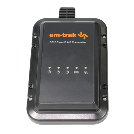
- Page 1 B212 AIS Class B Transceiver Product Manual High Performance Maritime Products www.em-trak.com...
- Page 2 Thank you for buying this AIS Class B transceiver. This product has been engineered to offer you the highest level of performance and durability and we hope that it will provide many years of reliable service. We constantly strive to achieve the highest possible quality standards, should you encounter any problems with this product, please contact your dealer who will be pleased to offer whatever assistance you require.
-
Page 3: Table Of Contents
Table of contents Table of figures Notices ....................1 Figure 1 The AIS network ................ 3 1.1 Safety warnings ..................1 Figure 2 Items included in the product............. 5 1.2 General notices ..................1 Figure 3 AIS transceiver overview ............6 About your AIS class B transceiver ...........3 Figure 4 Electrical connections to the AIS transceiver ...... -
Page 4: Notices
Notices 1 Notices Compass safe distance The compass safe distance of this unit is 0.5m or greater for 0.3° When reading this manual please pay attention to deviation. warnings marked with the warning triangle shown on RF emissions notice the left. These are important messages for safety, installation and usage of the product. - Page 5 Notices Disposal of this product and packaging Please dispose of the AIS transceiver in accordance with the European WEEE Directive or with the applicable local regulations for disposal of electrical equipment. Every effort has been made to ensure the packaging for this product is recyclable.
-
Page 6: Figure
A transceivers, class B transceivers, AtoNs and AIS basestations but do not transmit any information about the vessel on which they are installed. The em-trak B212 is a Class B AIS transceiver. Figure 1 The AIS network Page 3... -
Page 7: Static And Dynamic Vessel Data
About your AIS class B transceiver 2.2 Static and dynamic vessel data There are two categories of information transmitted by an AIS transceiver : static and dynamic data. The vessel's dynamic data, which includes location, speed over ground (SOG) and course over ground (COG), is calculated automatically using the internal GPS receiver. -
Page 8: What's In The Box
About your AIS class B transceiver 2.3 What's in the box? for details of the configuration process and how to use the proAIS tool. Figure 2 shows the items included with your AIS transceiver • Product manual purchase. The following sections give a brief overview of each item. This document is the product manual and should be read thoroughly Please ensure all items are present and if any of the items are not prior to any attempt to install or use the AIS transceiver. -
Page 9: Ais Transceiver Overview
About your AIS class B transceiver Figure 3 shows key features of the AIS transceiver. Please refer to Electrical connections section 3.2 for details of how to mount the AIS transceiver. The AIS transceiver has the following connections provided by the Do not attempt to adjust or remove the fixings next to attached cables: each of the four mounting holes. -
Page 10: Figure
Installation 3 Installation as that used with VHF voice radios will be sufficient. Please take note of the warnings in section 1 regarding the use of antennas. 3.1 Preparing for Installation Antenna cables If the supplied GPS antenna cable is not sufficient to reach between Figure 5 shows a typical installation configuration for the AIS the desired GPS antenna location and the AIS transceiver unit you transceiver. -
Page 11: Installation Procedures
Installation 3.2 Installation procedures to the NMEA0183 output connector as described in section 3.2. Please refer to the chart plotter manufactures documentation for further details on connection of AIS equipment and display Before beginning installation of your AIS transceiver, please ensure configuration. -
Page 12: Ais Transceiver Dimensions
Installation • It is recommended that the AIS transceiver is installed in a 'below decks' environment. • It is acceptable to mount the AIS transceiver either vertically or 137 mm 67 mm horizontally. • The product is supplied with four self tapping screws for attachment of the AIS transceiver to a suitable surface. -
Page 13: Figure
Installation Step 2 - Installing the GPS antenna For mounting of the GPS antenna provided with your AIS transceiver you will require a one inch 14 TPI thread pole. You should ensure the GPS antenna has a good clear view of the entire sky. -
Page 14: Gps Antenna Mounting
Installation Step 3 - Connecting the VHF antenna Route the cable from the VHF antenna to the AIS transceiver and connect to the VHF connector on the AIS transceiver as shown in Figure 10. A standard marine band VHF antenna or AIS antenna should be used with the AIS transceiver. -
Page 15: Nmea0183 Output Connections
Installation Step 4 - Connecting to a chart plotter The NMEA0183 data port (blue label) provides the connection to your chartplotter. Connection can either be made using the 9 way D- type connector provided, or by cutting off the connector and Power connecting the wires according to the colour code in the tables below. -
Page 16: Switch Connections
Installation Step 5 - Connecting mode switches Switch connection Connector pin (green connector) The mode switches connector (green label) provides connections Transmit power mode switch input for two toggle switches (not supplied). These switches can be used to control the AIS transceiver silent mode and transmitter power Silent mode switch input mode. -
Page 17: Rs232 Connection
Installation Step 6 - Connecting to a PC Step 7 - Connecting to a power supply The AIS transceiver is supplied with an RS232 port for connection The AIS transceiver requires a 12V power supply typically provided to a PC. The RS232 connector (red label) can be connected directly by the vessel's battery. -
Page 18: Configuring Your Ais Transceiver
Configuring your AIS transceiver 4 Configuring your AIS Prior to use the AIS transceiver requires programming with the vessel's static data to ensure that the data transmitted by the AIS transceiver transceiver matches that of the host vessel. US Customers only: It is a violation of the rules of the 4.1 Switching on your AIS transceiver Federal Communications Commission for the end user to programme the static data. -
Page 19: Introduction To The Proais Software
Configuring your AIS transceiver 4.2 Introduction to the proAIS software To install proAIS on your PC: 1. Locate and run the setup.exe file on the CD and then follow the Included in the CD supplied with your product is a configuration on-screen prompts. -
Page 20: Configuration Using Proais
Configuring your AIS transceiver 4.4 Configuration using proAIS • Call sign - the call sign can be up to seven characters in length. Not all vessels are issued with a call sign and it is acceptable to Please ensure that you enter all static data accurately. leave this field blank. -
Page 21: Operation
Operation 5 Operation Transmit timeout (amber) 5.1 Using the AIS transceiver This indicator will illuminate if the transceiver has been unable to transmit position reports on schedule. This could be caused by loss Once the unit has been configured it is ready for use. Providing of GPS position fix, high levels of AIS traffic or AIS base station other vessels with AIS transceivers installed are within radio range control. -
Page 22: Switch Functions
Operation 5.3 Switch functions 5.4 Using proAIS with your AIS transceiver External switches connected to the AIS transceiver can be used to control silent mode and high power mode. Please refer to section The proAIS tool has a range of features to help monitor the 3.2 for details about switch connections. -
Page 23: Figure
Operation proAIS GPS status page proAIS Diagnostics page The 'GPS status' page shows the signal strength of each satellite The 'Diagnostics' page provides a range of information about the being received and the dynamic data of the vessel. Satellite signals AIS transceiver's status. -
Page 24: Figure
Operation proAIS Other vessels page proAIS Messages page The 'Other vessels' page provides a list of all vessels from which The 'Messages' page provides a list of all text messages received AIS messages are being received. For each vessel the MMSI, from other vessels. -
Page 25: Proais Serial Data Page
Operation proAIS Serial data page The 'Serial data' page provides a view of all incoming and outgoing AIS messages. The messages are encoded in a special format and it is not necessary to understand the meaning of the messages to use the equipment. -
Page 26: Troubleshooting
Troubleshooting 6 Troubleshooting MMSI being • Some older AIS devices and chart plotters do not received by other vessels process the specific class B AIS message which but my vessel name is provides the vessel name (message 24). This is Issue Possible cause and remedy not shown on their chart... -
Page 27: Specifications
Specifications 7 Specifications Channel Bandwidth 25kHz Channel Step 25kHz Parameter Value Modulation Modes 25kHz GMSK (AIS, TX and RX) Dimensions 215 x 150 x 67 mm (L x W x H) 25kHz AFSK (DSC, RX only) Weight 685g (AIS transceiver unit only) Bit rate 9600 b/s ±... - Page 28 Specifications Page 25...
- Page 29 The em-trak B212 is an aid to navigation and must not be relied upon to provide accurate navigation information. AIS is not a replacement for vigilant human lookouts and other navigation aids such as Radar. The performance of the B212 may be seriously impaired if not installed as instructed in the user manual, or due to other factors such as weather and or nearby transmitting devices.
Need help?
Do you have a question about the B212 and is the answer not in the manual?
Questions and answers