Em-Trak B400 Installation And Operation Manual
Ais class b transceiver
Hide thumbs
Also See for B400:
- Installation manual (3 pages) ,
- Quick start manual (2 pages) ,
- Quick start manual (2 pages)
Table of Contents
Advertisement
Quick Links
Advertisement
Table of Contents

Related Manuals for Em-Trak B400


Summary of Contents for Em-Trak B400
- Page 1 B400 AIS Class B transceiver Installation and operation manual...
- Page 2 Thank you for purchasing this AIS Class B transceiver. This product has been engineered to offer you the highest level of performance and durability and we hope that it will provide many years of reliable service. We constantly strive to achieve the highest possible quality standards, should you encounter any problems with this product, please contact your dealer who will be pleased to offer any assistance you require.
- Page 3 List of abbreviations List of abbreviations Automatic Identification System AIS SART AIS Search and Rescue Transmitter Access Point (Relating to WiFi behaviour) AtoN AIS Aid to Navigation Compact Disc European Declaration of Conformity Course Over Ground Common (electrical) Closest Point of Approach Carrier Sense Direct Current Decimal...
- Page 4 List of abbreviations External Federal Communications Committee GNSS satellite fault detection message GNSS fix accuracy and integrity message Global positioning system (GPS) fix data message Geographic position - Latitude/longitude message GLONASS Globalnaya Navigazionnaya Sputnikovaya Sistema (Russian GNSS) Electrical Ground GNSS fix data message GNSS Global Navigation Satellite System Global Positioning System...
- Page 5 List of abbreviations Liquid Crystal Display Longitude Long Range Minimum Keyboard and Display MMSI Maritime Mobile Service Identity Man Overboard Normally Closed (electrical) Navigation Nautical Miles NMEA National Marine Electronics Association Portable Document Format Parameter Group Number Presentation Interface RAIM Receiver Autonomous Integrity Monitoring Radio Equipment Directive Radio Frequency...
- Page 6 List of abbreviations TDMA Time Division Multiple Access True heading and status message Threaded Neill–Concelman (a type of connector) Threads per Inch Transmit User Datagram Protocol Ultra High Frequency Co-ordinated Universal Time Dual ground/water speed message All VDL AIS messages received AIS own-ship broadcast data Very High Frequency VSWR...
-
Page 7: Table Of Contents
Table of contents Table of contents Notices ............9 Safety warnings ................9 General notices................10 Regulatory statements ..............11 Introduction ............ 15 About AIS..................15 Installation and configuration....... 17 What’s in the box? ................. 17 Preparing for installation ..............17 Installation procedures.............. - Page 8 Table of contents 4.10 Micro SD card data input..............55 4.11 WiFi Feature................... 57 Technical information........59 AIS Transceiver overall dimensions..........59 GNSS Antenna drawing ..............60 NMEA 2000 PGN List ..............61 Troubleshooting ................64 Technical specification ......... 67 Applicable equipment standards ............
- Page 9 List of figures and tables List of figures and tables Figure 1 The AIS network ..............15 Figure 2 What’s in the box? ............... 17 Figure 3 Typical AIS transceiver connection........19 Figure 4 Mounting the AIS transceiver..........21 Figure 5 Desk mounting the AIS transceiver ........
- Page 10 List of figures and tables Figure 29 AIS Transceiver dimensions ..........59 Figure 30 GNSS Antenna ..............60 Table 7 PGN Lists................63 Table 8 Troubleshooting ..............66 Page 8...
-
Page 11: Notices
Notices Notices When reading this manual please pay particular attention to warnings marked with the warning triangle symbol shown on the left. These are important messages for safety, installation and usage of the AIS transceiver. 1.1 Safety warnings This equipment must be installed in accordance with the instructions provided in this manual. -
Page 12: General Notices
Notices Do not attempt to service this equipment as doing so may cause fire, electric shock or malfunction and will invalidate the warranty. If any malfunctions are detected contact your supplier or service agent. NOT ALL SHIPS CARRY AIS. The Officer of the Watch should always be aware that other ships and, in particular, leisure craft, fishing vessels and warships may not be fitted with AIS. -
Page 13: Regulatory Statements
Notices 1.2.6 Accuracy of this manual This manual is intended as a guide to the installation, setup and use of this product. If you are in any doubt about any aspect of this product, please contact your dealer. 1.3 Regulatory statements 1.3.1 Declaration of Conformity The manufacturer of this product declares that this product is in compliance... - Page 14 Notices 1.3.2 FCC Notice This equipment has been tested and found to comply with the limits for a class B digital device, pursuant to part 15 of the FCC Rules. These limits are designed to provide reasonable protection against harmful interference in a residential installation. This equipment generates, uses and can radiate radio frequency energy and, if not installed and used in accordance with the instructions, may cause harmful interference to radio communications.
- Page 15 Notices 1.3.3 Industry Canada Notice This device complies with Industry Canada licence-exempt RSS standard(s). Operation is subject to the following two conditions: 1.This device may not cause interference, and 2.This device must accept any interference, including interference that may cause undesired operation of the device. This Class B digital apparatus complies with Canadian ICES-003.
- Page 16 Notices Page 14...
-
Page 17: Introduction
Introduction Introduction 2.1 About AIS The marine Automatic Identification System (AIS) is a location and vessel information reporting system. It allows vessels equipped with AIS to automatically and dynamically share and regularly update their position, speed, course and other information such as vessel identity with similarly equipped vessels. - Page 18 Introduction Page 16...
-
Page 19: Installation And Configuration
Installation and configuration Installation and configuration 3.1 What’s in the box? Please ensure all items are present and if any of the items are missing please contact your dealer. Flyer Warranty card AIS transceiver Product mounting template Quick start guide Mounting bracket Fixings GNSS Antenna... -
Page 20: Installation Procedures
Installation and configuration 3.2.1 VHF Antenna Connection of a suitable VHF antenna will be required for the AIS transceiver to operate. The antenna cable should be terminated with a PL-259 (or UHF) connector. A surge arrestor should be fitted in line with VHF antenna connector. - Page 21 Installation and configuration VHF antenna GNSS antenna Surge arrestor 12V DC to 24V DC Supply Chassis/GND Optional connections NMEA2000 Ship’s sensor data Displays etc. Figure 3 Typical AIS transceiver connection Page 19...
- Page 22 Installation and configuration 3.3.1 Step 1 - Installing the AIS transceiver Please note the following guidelines when selecting a location for your AIS transceiver: ● The AIS transceiver must be fitted in a location where it is at least 0.5m (1ft 8ins) from a compass or any magnetic device. ●...
- Page 23 Installation and configuration Panel mounted Desk mounted Overhead mounted (reverse mounting bracket) Figure 4 Mounting the AIS transceiver Refer to Figure 29. for dimensions. A drilling and cutting template is provided with the AIS transceiver. To panel mount the unit it is necessary to remove the 4 off socket cap screws recessed in front of the unit.
- Page 24 Installation and configuration Figure 5 Desk mounting the AIS transceiver Page 22...
- Page 25 Installation and configuration Figure 6 Panel mounting the AIS transceiver 3.3.2 Installing the GNSS antenna For mounting the GNSS antenna supplied with your AIS transceiver you will require a one inch 14 TPI pole mount. Contact your dealer to source a mount suitable for the installation location.
- Page 26 Installation and configuration ● The GNSS antenna should be located where it has a clear, unobstructed view of the sky overhead. ● The GNSS antenna should be mounted as high as possible, however it is not recommended to mount the antenna on the top of a high mast where the motion of the vessel will cause the antenna to move and potentially reduce the accuracy of the GNSS position.
- Page 27 Installation and configuration GNSS Antenna connection Figure 8 GNSS Antenna connection 3.3.3 Installing the VHF antenna Please note the following guidelines when selecting and locating the AIS VHF antenna: ● The VHF antenna should be located as high as possible and positioned as far from other antennas as possible.
- Page 28 Installation and configuration ● The VHF antenna cable should be kept as short as possible to minimize signal loss. High quality, low loss co-axial cable appropriate to the installation location should be used. ● The VHF antenna cable should be terminated in a PL-259 co-axial connector for connection to the AIS transceiver.
-
Page 29: Connecting The Equipment
Installation and configuration VHF antenna connection Figure 10 VHF Antenna connection 3.4 Connecting the equipment 3.4.1 Data connections The accessory cable provides a simple method of implementing a typical Class B installation with minimum difficulty. If the planned installation is more complex it is recommended to use the optional fully wired cables and Junction box for greater flexibility An accessory cable is supplied with the product to provide connections to the... - Page 30 Installation and configuration Port Name in Decription Wire Colour Function NMEA0183 NMEA0183 Black High speed Port 1 COM Port 1 NMEA0183 output (38,400baud) NMEA0183 NMEA0183 Blue/White intended for chart Port 1 TX B Port 1 plotters NMEA0183 NMEA0183 White/Blue Port 1 TX A Port 1 NMEA0183 NMEA0183...
- Page 31 Installation and configuration Without acessory cable AIS transceiver Chart plotter Gyro-compass Chart plotter Using accessory cable AIS transceiver Gyro-compass Chart plotter Figure 11 Using the accessory cable A multiplexing feature is provided, which means any messages which are received via the NMEA 2 port are automatically re-transmitted via the NMEA 1 port.
- Page 32 Installation and configuration It is important to ensure that the equipment is configured to use the matching baud rates. 3.4.2 Sensor configuration For more complex installations the AIS transceiver has six NMEA0183 (IEC61162-1/2) data ports for connection of ship’s sensors and display equipment as described in Table 2.
- Page 33 Installation and configuration SIGNAL WIRE COLOUR NOT USED BLACK NOT USED BROWN SILENT N BLUE SILENT P NMEA RX4 B ORANGE NMEA RX4 A PURPLE NMEA RX4 COM GREEN NMEA RX5 B WHITE NMEA RX5 A WHITE / BLACK NMEA RX5 COM GREY NMEA RX6 B YELLOW...
- Page 34 Installation and configuration Note: Any unused ports should be terminated by a 120 Ohm resistor across RX A and RX B signals. 3.4.4 Silent mode switch To activate the Silent mode switch, apply a voltage of between 2V and 30V to the SILENT P (Pin 7) and SILENT N (Pin 6) terminals of the 14 way connector.
- Page 35 Installation and configuration SIGNAL WIRE COLOUR NMEA TX1 B ORANGE NMEA TX1 A BROWN 15 14 NMEA RX1 B PURPLE NMEA RX1 A BLUE 11 10 NMEA 1 COM BLACK NMEA TX2 B NMEA TX2 A RED / WHITE NMEA RX2 B PINK NMEA RX2 A YELLOW...
- Page 36 Installation and configuration Note: Any unused ports should be terminated by a 120 Ohm resistor across RX A and RX B signals. COMMON signals should be grounded. All sensor ports can be configured via the Interface settings menu which can be found under the ‘Home’...
- Page 37 Installation and configuration 3.4.7 Power connection Power is connected to the AIS transceiver via the supplied 2 way power cable as shown in Figure 16. Power connection Figure 16 Power connection Wire colour Function Connect to Power supply + 12VDC to 24VDC power supply Black Power supply - Power supply ground...
-
Page 38: Grounding The Ais Transceiver
Installation and configuration ● A 24VDC supply should be able to provide a peak current of 3.0A and should be fused at 5.0A. 3.5 Grounding the AIS transceiver An M4 grounding screw and ring crimp are provided in the fixing kit to allow connection to the grounding point on the rear of the AIS transceiver chassis as indicated in Figure 17. -
Page 39: Connection To An Nmea2000 Network (Optional)
Installation and configuration 3.6 Connection to an NMEA2000 network (optional) The AIS transceiver can be connected to an NMEA2000 network by a suitable NMEA2000 network cable available from your local dealer. If your vessel has an NMEA2000 network please refer to the relevant documentation for your NMEA2000 equipment. - Page 40 Installation and configuration 16:58:29 SOG 21.1kt 50° 32.0286’ N COG 88.0° 0° 55.2715’ W UTC + 1h PASSWORD SETTINGS Enter the current password: Figure 18 Enter password screen Page 38...
-
Page 41: Operation
Operation Operation Please read the warning notices at the front of this manual before operating the AIS transceiver. 4.1 Using the AIS transceiver Once the unit has been configured it is ready for use. Providing other vessels with AIS transceivers installed are within radio range of your vessel you should see their details appear on your target list. -
Page 42: Display And Controls
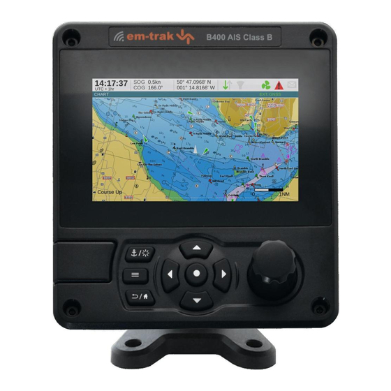
Operation 4.2 Display and controls Chart / Screen brightness Display Select Micro SD card slot behind door Options menu Back / Home Scroll wheel Function keys (push to select) (up, down, left right) Figure 19 AIS Transceiver front panel The front panel of the AIS transceiver is shown in Figure 19.with each control marked. -
Page 43: Adjusting Display Brightness
Operation Options menu key. Provides access to additional features and relevant shortcuts on certain screens. Back / Home key. When pressed with a short press cancels the current operation and moves to the previous menu or if pressed and held will return to the home screen. -
Page 44: Menu Navigation
Operation 4.5 Menu navigation 16:58:29 SOG 21.1kt 50° 32.0286’ N COG 88.0° 0° 55.2715’ W UTC + 1h HOME User settings Target list Target plot Chart Messages Alarms Own dynamic data System settings Figure 20 Home page menu screen 4.5.1 Main / Sub menus Menus are displayed as a set of icons which can be navigated by using the controls. - Page 45 Operation DISPLAY SETTINGS SOUND SETTINGS HOME LANGUAGE SENSOR PORT 1 TARGET LIST TIME SENSOR PORT 2 USER SETTINGS FILTER & CPA/TCPA SETTINGS SENSOR PORT 3 TARGET PLOT WiFi MESSAGE INBOX CHART GNSS OUTPUT SENT MESSAGES MESSAGES NMEA0183 PORT 1 COMPOSE MESSAGE ALARMS NMEA0183 PORT 2 NMEA0183 PORT 3...
-
Page 46: Information Displayed
Operation 4.5.4 Options menu On certain screens, the Options Menu will bring up a further list of functions specific to that screen. This is indicated by this icon. 4.6 Information displayed Position Speed / Course Filtering Power setting Time GNSS Status Time offset Alarms 16:58:29... - Page 47 Operation 4.6.4 Speed / Course Vessel speed and course as taken from GNSS satellite data. 4.6.5 Position Vessel position taken from GNSS source. 4.6.6 Icons RX - Illuminates to show receiving an AIS message. TX - Illuminates to show transmission of an AIS message. Filtering - Illuminated to show that target filter settings apply.
- Page 48 Operation 4.6.7 Alarms The AIS transceiver performs self checking functions continuously. If a self check fails a display will appear on the screen notifying the operator of this. This will be accompanied by a sound. The alarm can be acknowledged via an on-screen message.
- Page 49 Operation Possible alarm conditions are listed Table 6. Alarm Description TX Malfunction This alarm will occur if the MMSI has not been configured. This alarm can also occur if the radio hardware has failed to select the correct frequency, that the output power is too low or a transmitter shutdown has occurred.
- Page 50 Operation Alarm Description Heading lost or invalid This alarm occurs if the AIS transceiver has no valid heading information from any connected sensor, or if the heading is undefined. No sensor position in use This alarm occurs if the AIS transceiver has no valid position information from any connected sensor.
- Page 51 Operation not displayed on receipt, however the message icon will be displayed at the top of the screen. AIS messages can be viewed, created and transmitted from the ‘Messages’ menu. The available options are: Compose - takes you to the message composition screen Inbox - takes you to the received message list view Sent - shows a list of recently sent messages.
-
Page 52: Configuring Vessel Information
Operation SOG vectors can also be displayed on the screen if this item is selected from the ‘Options’ menu. Some of the layers displayed on the chart can be removed to provide more clarity on the display. The ‘Chart Settings’ screen provides a way of modifying these. - Page 53 Operation ● Ship type - Selected from the menu provided. ● Reference dimensions of the location of the GNSS antenna connected directly to the AIS transceiver. Please ensure that you enter all vessel data accurately. Failure to do so could result in other vessels failing to identify your vessel correctly.
-
Page 54: Confirming Correct Operation
Operation GNSS Antenna Ref C Stern Ref B Ref A Ref D Ref A + Ref B = Length in metres Ref C + Ref D = Beam in metres Figure 25 Vessel dimension measurement 4.8 Confirming correct operation Following entry of the vessel information the AIS transceiver will commence normal operation. -
Page 55: Displaying Ais Targets
Operation 4.9 Displaying AIS targets 4.9.1 Target list The ‘Target list’ screen is the primary screen for displaying AIS targets received. This is the first screen displayed when the unit is switched on, but can also be accessed from the ‘Target list’ option on the ‘Home’ menu. 16:58:29 SOG 21.1kt 50°... - Page 56 Operation Different symbols are shown for an AIS target depending on the type of target and its status, these are shown in Figure 27. These symbols are common to the ‘Target list’ and ‘Target plot’ displays. Base station Virtual AIS AtoN AIS Class A AIS Class B AIS SART...
-
Page 57: Micro Sd Card Data Input
Operation These CPA/TCPA figures are calculated solely on AIS data and should not be used for anti-collision purposes. Note: Setting the CPA/TCPA filter will not activate the Filters Icon. 4.9.4 Target plot The ‘Target plot’ screen shows the location of other AIS equipped vessels and shore stations relative to your own vessel. - Page 58 Operation Figure 28 Micro SD card Socket 4.10.1 Loading new charts The AIS transceiver always contains a basic low resolution world chart. More detailed resolution charts can be purchased and overlaid onto the AIS transceiver’s chart display. The AIS transceiver will read only C-MAP MAX format Micro SD cards. See your dealer for available charts for your region.
-
Page 59: Wifi Feature
Operation 4.10.2 Upgrading the unit firmware If a Micro SD card that contains valid upgrade firmware is inserted into the card socket, the unit will recognize the new firmware and will display a message asking you if you want to install it. The system will guide you to the appropriate menu screen, where the firmware update can be applied. - Page 60 Operation 4.11.2 Access point mode If the AIS transceiver is configured as a WiFi access point (AP) it will create its own WiFi network, allowing other WiFi enabled devices to connect to it. Up to 5 simultaneous connections are supported. Once connections are made, a range of NMEA0183 sentences will be transmitted from the AIS transceiver to any connected devices.
-
Page 61: Technical Information
Technical information Technical information 5.1 AIS Transceiver overall dimensions 75 mm 152 mm 48 mm 130 mm Figure 29 AIS Transceiver dimensions Page 59... -
Page 62: Gnss Antenna Drawing
Technical information 5.2 GNSS Antenna drawing 75 mm* 10m RG58 cable TNC (male) Figure 30 GNSS Antenna * The dimensions of the supplied antenna may vary from those shown here. Page 60... -
Page 63: Nmea 2000 Pgn List
Technical information 5.3 NMEA 2000 PGN List The PGN’s listed in Table 7. are supported by the AIS transceiver. There are no unused fields. Title in NMEA database Usage NMEA 0183 (Dec.) (Hex) 059392 0E800 ISO Acknowledgment in, out 059904 0EA00 ISO Request in, out... - Page 64 Technical information Title in NMEA database Usage NMEA 0183 (Dec.) (Hex) 129038 1F80E AIS Class A Position VDM/VDO Report 129039 1F80F AIS Class B Position VDM/VDO Report 129040 1F810 AIS Class B Extended VDM/VDO Position Report 129041 1F811 AIS AtoN Report VDM/VDO 129793 1FB01...
- Page 65 Technical information Table 7 PGN Lists Page 63...
-
Page 66: Troubleshooting
Technical information 5.4 Troubleshooting Issues Possible cause and remedy No data is being ● Check that the power supply is received by a connected connected correctly. chart plotter ● Check that the power supply is a 12VDC or 24VDC supply. ●... - Page 67 Technical information The RED ‘Alarm’ icon is ● The unit may not have a valid MMSI. illuminated or flashing Check that the AIS transceiver is correctly configured with a valid MMSI. ● The VHF antenna may be faulty. Please check the connection to the VHF antenna and that the VHF antenna is not damaged.
- Page 68 Technical information My MMSI is being ● Some older AIS devices and chart received by other plotters do not process the specific vessels but my vessel class B message which provides the name is not shown on vessel name (message 24). This is their chart plotter or PC.
-
Page 69: Technical Specification
Technical specification Technical specification 6.1 Applicable equipment standards IEC62287-2 Maritime navigation and radiocommunication Ed. 1.0 equipment and systems - Class B 2013-03 shipborne equipment of the universal automatic identification system (AIS) – Part 2: Self-organising time division multiple access (SOTDMA) techniques IEC60945 Maritime navigation and radio communication 4th Ed. -
Page 70: Product Category
Technical specification ITU-R M.1371-5 Technical characteristics for an automatic 02/2014 identification system using time division multiple access in the VHF maritime mobile band IEC61108-1 Global Navigation Satellite Systems (GNSS) – 2nd Ed. Part 1: Global positioning system (GPS) - Receiver 2003-07 equipment - Performance standards, methods of testing and required test results... -
Page 71: Environmental
Technical specification 6.4 Environmental ° ° Operating temperature C to +55 range ° Maximum operating 90% at +40 C, non-condensing humidity Water ingress rating IPx6, IPx7 6.5 Electrical Supply voltage 12VDC to 24VDC (absolute min 10.8V, absolute max 31.2 V) Power consumption <... -
Page 72: Internal Gnss
Technical specification 6.7 Internal GNSS Receiver 72 channels GPS, GLONASS and BeiDou operating channels modes Time to first fix Typically 26 seconds Frequency L1 GPS band 1575.42MHz L1 GLONASS band 1597.1 - 1609.5MHz B1 BeiDou band 1561.098MHz Accuracy 2.5m CEP / 5.0m SEP without differential correction 2.0m CEP / 3.0m SEP with SBAS or RTCM DGNSS correction Antenna... -
Page 73: Dsc Receiver
Technical specification Modulation mode 25kHz GMSK Adjacent channel selectivity 70dB Spurious response rejection 70dB 6.10 DSC Receiver Number of receivers Frequency 156.525MHz (Channel 70) Channel bandwidth 25kHz Sensitivity -107dBm @ BER <10 Modulation mode 25kHz AFSK Adjacent channel selectivity 70dB Spurious response rejection 70dB 6.11 RF Connections... -
Page 74: Wifi
Technical specification 6.12 WiFi Maximum output power IEEE 802.11g/n +15dBm Maximum output power IEEE 802.11b +17dBm 6.13 Data interface Sensor data input ports Number of ports Standard IEC61162-1 / -2 Baud rate 4800 baud or 38400 baud Port impedance 54K Ohms Bi-directional data ports Number of ports Standard... -
Page 75: Power And Data Connector Information
Technical specification Silent Mode port Port impedance 10K Ohms NMEA 2000 Port: Load equivalency number (LEN) 6.14 Power and data connector information Power Chogori Mating Half Chogori connector 22002525-04-RC 22002221-01 18 way data Chogori Mating Half Chogori connector 23018525-04-RC 23018221-01 14 way data Chogori Mating Half... - Page 76 Technical specification Page 74...
- Page 78 Manufacturer’s code: 427 NMEA 2000 Product code: 23810 201-0709:6...
Need help?
Do you have a question about the B400 and is the answer not in the manual?
Questions and answers