Table of Contents
Advertisement
Quick Links
Advertisement
Table of Contents

Related Manuals for Em-Trak B200


Summary of Contents for Em-Trak B200
- Page 1 B200 USER MANUAL Class B AIS Transceiver...
- Page 2 We constantly strive to achieve the highest possible quality standards, should you encounter any problems with this product, please contact your dealer or support@em-trak.com who will be pleased to offer any assistance you require.
-
Page 3: Table Of Contents
Table of contents Table of contents Regulatory notices ........3 Safety warnings ................3 General notices................3 About your AIS transceiver .......8 Overview ..................8 What's in the box? ................10 Support and warranty ..............10 Configuration tool.................11 Installation ............12 Summary ..................12 Antennas ..................14 Power and Data ................17 Location and fixing of the transceiver........20 Configuration .................22 Introduction to proAIS2 ..............23... - Page 4 List of figures and tables List of figures and tables Figure 1 AIS transceiver overview ..........8 Figure 2 Transceiver dimensions............ 9 Figure 3 Items included with the product ........10 Figure 4 Typical installation configuration ........12 Figure 5 Position of the VHF antenna connector .......
-
Page 5: Regulatory Notices
Regulatory notices Regulatory notices When reading this manual please pay attention to warnings marked with the warning triangle shown on the left. These are important messages for safety, installation and usage of the product. Safety warnings This equipment must be installed in accordance with the instructions provided in this manual. - Page 6 Regulatory notices The accuracy of a GPS position fix is variable and is affected by factors such as the antenna positioning, how many satellites are used to determine a position and how long satellite information has been received for. The term GPS will be used in this manual to mean all and any GNSS systems.
- Page 7 Regulatory notices 1.2.4 Disposal of this product and packaging Please dispose of the AIS transceiver in accordance with the European WEEE Directive or with the applicable local regulations for disposal of electrical equipment. Every effort has been made to ensure the packaging for this product is recyclable.
- Page 8 AIS with their vessel data. To do so is a violation of the rules of the United States Coast Guard (USCG). This must be done by a competent installer, such as em-trak, an em-trak dealer or competent marine electronics professional. If your transceiver has not been pre-configured for you please refer to your dealer or contact support@em-trak.com for advice on how to have the...
- Page 9 Regulatory notices In the United States of America, the MMSI and static data must only be entered by a competent installer. The end user of the equipment is not authorised to enter their own vessel data. 1.2.9 Industry Canada notice This device complies with Industry Canada license-exempt RSS standard(s).
-
Page 10: About Your Ais Transceiver
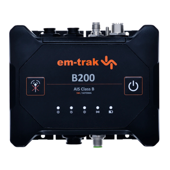
About your AIS transceiver 2 About your AIS transceiver 2.1 Overview LED indicators Silent mode button On / off button NMEA 2000 Mounting holes GPS antenna NMEA 0183 Power VHF antenna Ground stud Mounting holes Figure 1 AIS transceiver overview Page 8... - Page 11 •Internal battery back-up for up to 24 hours operation. •IPx7 tested and certified for complete water submersion and IPx6 tested and certified for high pressure spray. The B200 is able to be installed and operated permanently outdoors in a fully exposed location or in a location where it will be exposed to extreme hot or cold temperatures, damp, salt air and water.
-
Page 12: What's In The Box
About your AIS transceiver 2.2 What's in the box? Figure 3 shows the items included with your B200 purchase. If any of the items are not present please contact your dealer or support@em-trak.com. Document pack Class B AIS transceiver antenna... -
Page 13: Configuration Tool
Support department (24/7) at support@em-trak.com and one of our experts will work with you to instantly resolve your issue or arrange the repair or replacement of your em-trak product. The warranty is invalidated if the product has been incorrectly used, damaged or tampered. -
Page 14: Installation
If after reading this manual you are unsure about any element of the installation process please contact your dealer or support@em-trak.com for advice. NMEA 0183 Chartplotter... - Page 15 Installation In addition to the items supplied, the following may also be required for your installation: •VHF antenna and cable - this is required for your transceiver to receive and transmit. A VHF antenna installation is covered in more detail in Section 3.2.1. If you need to extend the antenna cable when connecting to your existing VHF antenna, RG-58 or RG-8X can be used for short distances.
-
Page 16: Antennas
VHF antenna Connection to a suitable VHF antenna will be required for the transceiver to receive and transmit. If the B200 is not connected to an antenna splitter it will require a dedicated VHF antenna tuned to 162MHz. VHF antenna... - Page 17 Installation 3.2.2 Earthing the AIS Transceiver An M5 ground connection point stud is provided adjacent to the VHF antenna connector. There is also an M5 nut and shake-proof washer provided in the fixing kit to allow connection to the ground connection point as indicated in Figure 6.
- Page 18 Installation 3.2.3 GPS Antenna The B200 has a high-performance GPS receiver that is compatible with the GPS, GLONASS, Galileo, and BeiDou satellite navigation systems. GPS and Galileo systems are always used and proAIS2 can be used to select between GLONASS and BeiDou as the third system.
-
Page 19: Power And Data
Installation 3.3 Power and Data 3.3.1 Connecting the data cable A data cable is supplied with the product to provide connections for two NMEA 0183 data ports and the optional silent mode switch. The cable has a moulded connector at one end which should be connected to the 12 pin connector on the unit. - Page 20 Installation The table below lists the function of each colour coded wire for reference. Wire Description Function colour Light Switch connection External switch connections Green for silent mode Orange Switch connection Brown NMEA 0183 port 1 TX+ High speed NMEA 0183 output (38,400baud) Blue NMEA 0183 port 1TX-...
- Page 21 Installation 3.3.2 Connecting the power cable The AIS transceiver is designed to operate at voltages from 9.6-31.2V, however for optimum performance we would recommend maintaining the voltage range at 12-24V. It is recommended that crimped and soldered lugs are used to connect the AIS transceiver to the power source using a suitable circuit breaker and/or 4A fuse block.
-
Page 22: Location And Fixing Of The Transceiver
LED indicators are readily visible as they provide important information on the status of the transceiver. •WiFi & Bluetooth will benefit from the B200 being installed near the center of the boat to provide a consistent signal across all areas. The construction of your vessel can also have an impact on performance. - Page 23 Installation 96 mm 60 mm 169 mm Figure 10 AIS transceiver dimensions Page 21...
-
Page 24: Configuration
Installation Figure 11 AIS transceiver mounting 3.5 Configuration Your transceiver will only be able to transmit once it has been configured with appropriate vessel data. 3.5.1 Switching on your AIS transceiver for the first time When power is applied to the transceiver for the first time all the status LED indicators will flash briefly, leaving only the amber and red LED indicators illuminated. -
Page 25: Introduction To Proais2
GPS antenna performance, view details on surrounding vessels, and monitor and diagnose the performance of the transceiver. Further information on how to use proAIS2 can be found in the FAQ section for this product - https://em-trak.com/ installation/ Page 23... - Page 26 The vessel MMSI can only be configured once using proAIS2. If you need to change the MMSI for any reason, please contact your dealer or support@em-trak.com and provide the product serial number, current MMSI number and new MMSI number. Page 24...
- Page 27 3.6.4 Access point mode This mode enables your transceiver to create its own network. The following parameters can be configured: • AP SSID (the default is <B200>_<alphanumeric number>) • IP address (the default is 192.168.2.1) • Password (the default is emtrakais) •...
- Page 28 Installation For security purposes there is a 5 minute window from initialisation where the Bluetooth interface is available for pairing. After this window expires it will disappear from device lists. Active connections will not be affected by this. If you wish to make the Bluetooth interface visible again for a further 5 minutes press the on/off button to enter standby mode then exit standby mode by pressing the on/off button again.
-
Page 29: Connectivity
Installation 3.7 Connectivity 3.7.1 Connecting to an NMEA 2000 network The transceiver can be connected to an existing NMEA 2000 network to provide AIS and position data to other connected devices such as chartplotters, instruments, sensors, etc. Connection is made by a Micro-C drop cable to the existing NMEA 2000 network T-piece. - Page 30 Installation proAIS2 if required. Four wires are provided for a bi-directional connection, and are colour coded as shown in Figure 15. Other manufacturers may use different signal names, however the following general guidelines will apply when connecting to other equipment: •positive signals should be connected together •negative signals should be connected together •transmit signals should be connected to receive signals and...
- Page 31 (Windows 7 and up). These are installed automatically by using either Windows Update or when installing proAIS2. proAIS2 is available for download from www.em-trak.com/installation. USB drivers are typically not required for macOS operating systems. Once your transceiver is communicating with your PC or laptop you can view the received AIS data using a compatible navigation application.
- Page 32 SSID - at default it appears as <B200>_<alphanumeric number> but it can be changed using the WiFi tab on proAIS2 if required. To stream AIS data to a navigation application you may then need to enter the IP address and port number.
-
Page 33: Operation
Operation 4 Operation 4.1 Operating modes The B200 has 3 modes of operation and a standby mode. When external power is present, the transceiver is in Normal mode. When external power is removed, the B200 enters one of two modes, Normal Back-up or Emergency Back-up, depending on how the transceiver has been configured using proAIS2. -
Page 34: Led Indicators
Operation 4.2 LED indicators 4.2.1 Using the AIS transceiver Once the unit has been configured it is ready for use. Providing other vessels installed with transceivers are within radio range of your vessel you will see their details appear on the display devices that you have connected to your transceiver. - Page 35 Section 4.4. Amber LED indicator Indicates that the B200 is not transmitting. This can be for a number of reasons: •The AIS radio channels are exceptionally busy so there are currently no available slots for transmission.
-
Page 36: Buttons
Diagnostics tab of proAIS2. 4.3.2 On / off button The on / off button allows the B200 to be put into standby mode or switched off completely. In standby mode the B200 stops transmitting, receiving and communicating with other equipment. -
Page 37: Silent Mode
Operation The B200 will turn on and return to normal operation when external power returns. 4.4 Silent mode An external switch enables / disables ‘silent mode'. In silent mode the transmission of your own vessel position ceases, whilst the reception of other vessel's AIS position continues. When silent mode is active the blue LED indicator will be illuminated. - Page 38 Operation Light green Switch connection Orange Switch connection Brown Transmit + Blue Transmit – NMEA 0183 White Port 1 Receive + Green Receive – Purple Transmit + Pink Transmit – NMEA 0183 Grey Port 2 Receive + Yellow Receive – Figure 19 Connecting an external switch Page 36...
-
Page 39: Pgn Table
Operation 4.5 PGN table PGN’s are useful for understanding the detailed information that your transceiver receives and transmits on an NMEA 2000 network. The PGN’s listed in Table 3 are supported by the transceiver. There are no unused fields. PGN No. Title in NMEA database Usage NMEA 0183... - Page 40 Operation 129029 GNSS Position data 129038 AIS Class A Position Report VDM/VDO 129039 AIS Class B Position Report VDM/VDO 129040 AIS Class B Extended Position VDM/VDO Report 129041 AIS AtoN Report VDM/VDO 129793 AIS UTC and Date Report VDM/VDO 129794 AIS Class A Static and Voyage VDM/VDO Related Data...
-
Page 41: Troubleshooting
Troubleshooting 5 Troubleshooting Issue Possible cause and remedy • Check that the power supply is connected No LED correctly. indicators are illuminated • Check that the power supply is a 12V or 24V supply. The red error There may be a problem with the VHF LED indicator is antenna system. - Page 42 Troubleshooting • Your transceiver is unable to get a GPS fix. The amber LED You can check the performance of the GPS indicator is antenna by using the GPS Status tab of flashing proAIS2. continuously • Check that the signal wires are connected No data is being correctly.
- Page 43 Troubleshooting If the guidance given above does not rectify the problem you are experiencing, please contact your dealer or support@em-trak.com for further assistance. Page 41...
-
Page 44: Specifications
Specifications 6 Specifications Parameter Value Dimensions 171 x 128 x 60 mm (L x W x H) Weight 685g Input voltage DC 12 - 24V (9.6 - 31.2V maximum) Average Normal operation: 240mA / 2.9W at 12VDC power Charging batteries: 1.6A / 19.2W at 12VDC consumption Peak current rating... - Page 45 Specifications Transmitter x 1 Transceiver Receiver x 2 (Receivers time shared between AIS and DSC) Frequency: 156.025 to 162.025 MHz in 25 kHz steps Output Power 37dBm ± 1.5 dB Channel 25kHz Bandwidth Channel Step 25kHz Modulation 25kHz GMSK (AIS, TX and RX) Modes 25kHz AFSK (DSC, RX only) Bit rate...
-
Page 46: About Ais
About AIS 7 About AIS The marine Automatic Identification System (AIS) is a location and vessel information reporting system. It allows vessels equipped with AIS to automatically and dynamically share and regularly update their position, speed, course and other information such as vessel identity with similarly equipped vessels. -
Page 47: Static And Dynamic Vessel Data
About AIS AtoN’s and AIS base stations but do not transmit any information about the vessel on which they are installed. 7.1 Static and dynamic vessel data There are two categories of information transmitted by a transceiver: static and dynamic data. The vessel's dynamic data, which includes location, speed over ground (SOG) and course over ground (COG), is calculated automatically using the integrated GPS receiver. - Page 48 About AIS Page 46...
-
Page 49: List Of Abbreviations
List of abbreviations List of abbreviations Automatic Identification System Access Point (Relating to WiFi behaviour) AtoN AIS Aid to Navigation European Declaration of Conformity Course Over Ground Common (electrical) Carrier Sense Direct Current DHCP Dynamic Host Configuration Protocol Digital Selective Calling Federal Communications Committee Geographic position - Latitude/longitude message GLONASS... - Page 50 List of abbreviations Parameter Group Number Radio Equipment Directive Radio Frequency Recommended minimum specific GPS data message Rate of Turn Receive Self Organised Speed Over Ground SOLAS Safety of Life at Sea Safety Related Message TDMA Time Division Multiple Access True heading and status message Threaded Neill–Concelman (a type of connector) Threads per Inch...
- Page 52 The em-trak B200 transceiver is an aid to navigation and must not be relied upon to provide accurate navigation information. AIS is not a replacement for vigilant human lookouts and other navigation aids such as RADAR. The performanceof the B200 may be seriously impaired if not installed as instructed in the user manual, or due to other factors such as weather and or nearby transmitting devices.
Need help?
Do you have a question about the B200 and is the answer not in the manual?
Questions and answers