
Subscribe to Our Youtube Channel
Related Manuals for Em-Trak B330


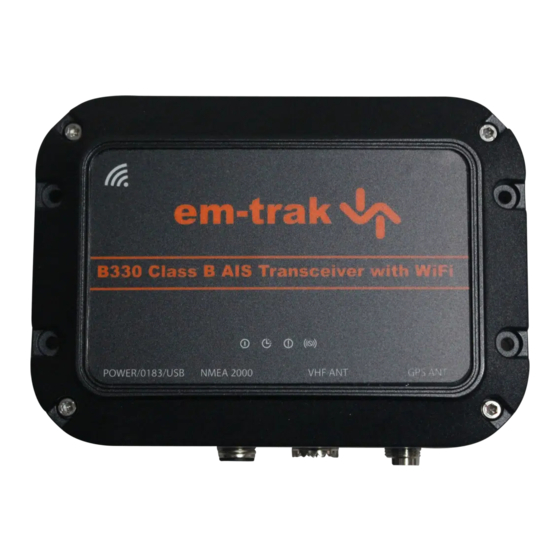
Summary of Contents for Em-Trak B330
- Page 1 B330 Class B AIS Transceiver S Tra S T ansceiver Tr r a a a ansceiv r Product manual anual www.em-trak.com High Performance Marine Products...
- Page 2 Thank you for buying this AIS Class B transceiver. This product has been engineered to offer you the highest level of performance and durability and we hope that it will provide many years of reliable service. We constantly strive to achieve the highest possible quality standards, should you encounter any problems with this product, please contact your dealer who will be pleased to offer whatever assistance you require.
-
Page 3: Table Of Contents
Table of contents Table of figures 1 - Notices ................. 1 Figure 1 Items included with the product......6 1.1 - Safety warnings..............1 Figure 2 AIS transceiver overview........8 1.2 - General notices ..............1 Figure 3 Electrical connections to the AIS transceiver ..9 2 - About your AIS class B transceiver ........ -
Page 4: Notices
Notices Notices When reading this manual please pay attention to warnings marked with the warning triangle shown on the left. These are important messages for safety, installation and usage of the product. Safety warnings This equipment must be installed in accordance with the instructions provided in this manual. This AIS transceiver is an aid to navigation and must not be relied upon to provide accurate navigation information. - Page 5 Notices the AIS transceiver and using antennas with a maximum gain of 3dBi.The antenna should be mounted 3.5m above the deck in order to meet RF exposure requirements. Higher gain antennas will require a greater MPE radius. Do not operate the unit when anyone is within the MPE radius of the antenna (unless they are shielded from the antenna field by a grounded metallic barrier).
-
Page 6: Figure
Notices FCC notice This equipment has been tested and found to comply with the limits for a class B digital device, pursuant to part 15 of the FCC Rules. These limits are designed to provide reasonable protection against harmful interference in a residential installation. This equipment generates, uses and can radiate radio frequency energy and, if not installed and used in accordance with the instructions, may cause harmful interference to radio communications. -
Page 7: About Your Ais Class B Transceiver
About your AIS class B transceiver About your AIS class B transceiver About AIS The marine Automatic Identification System (AIS) is a location and vessel information reporting system. It allows vessels equipped with AIS to automatically and dynamically share and regularly update their position, speed, course and other information such as vessel identity with similarly equipped vessels. -
Page 8: Important Information For Us Customers
About your AIS class B transceiver In most countries the operation of an AIS transceiver is included under the vessel's marine VHF licence provisions. The vessel on to which the AIS unit is to be installed must therefore possess a current VHF radiotelephone licence which lists the AIS system, vessel Call Sign and MMSI number. -
Page 9: What's In The Box
About your AIS class B transceiver What's in the box? Section Figure 1 shows the items included with your AIS transceiver purchase. The following sections give a brief overview of each item. Please ensure all items are present and if any of the items are not present contact your dealer. 4 x mounting screws Class B AIS transceiver 2 x anti-tamper screws... - Page 10 About your AIS class B transceiver Quick start guide The quick start guide gives a handy one page reference for the installation process. Product manual This document is the product manual and should be read thoroughly prior to any attempt to install or use the AIS transceiver. Fixing screws Four fixing screws are provided with the product for mounting of the AIS transceiver.
-
Page 11: Figure
About your AIS class B transceiver Indicator lights Green Amber Blue Mounting Mounting holes holes Power and data GPS antenna NMEA 2000 VHF antenna Figure 2 AIS transceiver overview Electrical connections The AIS transceiver has the following electrical connections: • Power supply •... -
Page 12: Figure
About your AIS class B transceiver AIS Class B Power in transceiver Switch NMEA0183 port NMEA 2000 Figure 3 Electrical connections to the AIS transceiver Page 9... -
Page 13: Installation
Installation Installation Preparing for Installation Section Figure 4 shows a typical installation configuration for the AIS transceiver. Please take the time to familiarise yourself with the system elements and their connections prior to attempting installation. Chartplotter VHF antenna GPS antenna AIS Class B (optional) transceiver... -
Page 14: Figure
Installation VHF antenna Connection to a suitable VHF antenna will be required for the AIS transceiver to operate. A standard marine band VHF antenna such as that used with VHF voice radios will be sufficient. Please take note of the warnings in section Section 1 regarding the use of antennas. Alternatively, if you wish to use an existing VHF antenna, antenna splitter products are available which allow the existing antenna to be used with two radio devices, such as a VHF voice radio and the AIS transceiver. -
Page 15: Installation Procedures
Installation Connection to a computer If you choose to use a computer with suitable charting software to display received AIS messages as other vessels, this can be accomplished by connecting the USB connector on the supplied power and data cable. Installation procedures Before beginning installation of your AIS transceiver, please ensure you have the necessary additional items as detailed in section Section 3.1. - Page 16 Installation • The ambient temperature around the AIS transceiver should be maintained between -25°C and +55°C. • The AIS transceiver should not be located in a flammable or hazardous atmosphere such as in an engine room or near to fuel tanks. •...
-
Page 17: Ais Transceiver Dimensions
Installation 128 mm 42 mm 140 mm Figure 6 AIS transceiver dimensions Page 14... -
Page 18: Ais Transceiver Mounting
Installation Figure 7 AIS transceiver mounting Page 15... -
Page 19: Gps Antenna Mounting
Installation Step 3 - Installing an optional external GPS antenna For mounting of the optional external GPS antenna you will require a one inch 14 TPI thread pole. You should ensure the GPS antenna has a good clear view of the entire sky. It is not recommended that the GPS antenna is mounted up a mast where the motion of the vessel will cause the antenna to swing and potentially reduce the accuracy of the GPS position. -
Page 20: Position Of The Gps Antenna Connector
Installation Power and data GPS antenna NMEA 2000 VHF antenna Figure 9 Position of the GPS antenna connector Page 17... -
Page 21: Position Of The Vhf Antenna Connector
Installation Step 4 - Connecting the VHF antenna Route the cable from the VHF antenna to the AIS transceiver and connect to the VHF connector on the AIS transceiver as shown in Section Figure 10. A standard marine band VHF antenna or AIS antenna should be used with the AIS transceiver. The connector type on the AIS transceiver is SO-239. - Page 22 Installation Step 5 - Connecting the accessory cable An accessory cable is supplied with the product to provide connections to power, the external switch, the NMEA0183 data port and USB. The cable has a pre-moulded connector at one end which should be connected to the connector on the unit marked 'PWR/DATA'. The other end of the cable has eight colour coded bare wires ready for connection and a USB connector for use with a computer.
-
Page 23: Connecting An External Switch
Installation Step 6 - Connecting an external switch A toggle switch can be connected to the AIS transceiver to provide remote control of silent mode. Connect the toggle switch between the light green and orange wires as shown in Section Figure 11. Connection of an external switch to toggle silent mode is optional and not essential for normal operation of the product. -
Page 24: Connecting To The Nmea0183 Data Port
Installation Step 7 - Connecting to NMEA0183 compatible equipment The NMEA0183 data port provides connection to your chart plotter or other NMEA0183 compatible equipment. The port consists of four wires colour coded as shown in Section Table 1 and Section Figure 12. Connect the wires to the appropriate connections on your NMEA0183 compatible equipment. - Page 25 Installation Step 8 - Connection to an NMEA2000 network (optional) The AIS transceiver can be connected to an NMEA2000 network by a suitable NMEA2000 network cable available from your local dealer. If your vessel has an NMEA2000 network please refer to the relevant documentation for your NMEA2000 equipment. Once connected, and with your chart plotter also connected to your NMEA2000 network you will be able to receive AIS targets on your chart plotter.
-
Page 26: Connecting The Power Supply
Installation Step 10 - Connecting to a power supply The AIS transceiver requires a 12V or 24V power supply typically provided by the vessel's battery. It is recommended that crimped and soldered lugs are used to connect the AIS transceiver to the power source. It is recommended that the power supply is connected via a suitable circuit breaker and/or 3A fuse block. -
Page 27: Configuring Your Ais Transceiver
Configuring your AIS transceiver Configuring your AIS transceiver Until correctly configured your AIS class B transceiver will only receive AIS messages and will not transmit AIS messages. By default, the anti-tamper mode of operation is disabled. Section 6 details how this can be configured. Switching on your AIS transceiver for the first time A few seconds after power is applied to the AIS transceiver, the indicators on unit will illuminate in a pattern dependent on the state of the unit. -
Page 28: Installing Proais2
Configuring your AIS transceiver Installing proAIS2 Insert the CD into your computer then locate and run the setup.exe file on the CD and follow the on-screen prompts. If a security warning appears, click 'Install' to continue with the installation. Once installation is complete, proAIS2 will launch automatically and a start menu folder and shortcut will be created for future use. Configuration using proAIS2 For configuration purposes only, it is possible to power the AIS transceiver via its USB connection. -
Page 29: Operation
Operation Operation Using the AIS transceiver Once the unit has been configured it is ready for use. Providing other vessels with AIS transceivers installed are within radio range of your vessel you should see their details appear on your chart plotter or PC. These vessels will also be able to see your vessel on their chart plotter or PC. -
Page 30: Indicator Functions
Operation Indicator functions The AIS transceiver includes four coloured indicators as shown in Section Figure 14. The state of the indicators provides information regarding the status of the AIS transceiver. Indicator lights Green Amber Blue Figure 14 Indicator location on the AIS transceiver unit The meaning of typical indicator configurations is shown in the table below and Section Figure 14 shows the orientation of the AIS transceiver. - Page 31 Operation Red indicator The AIS transceiver has detected a system error. The likely causes of this are detailed in the troubleshooting guide in section Section 9. Diagnostic messages displayed in proAIS2 may also help troubleshoot the cause of the error. Blue indicator When silent mode is activated using the optional silent mode switch the blue indicator is illuminated to show that the transmitter is disabled.
-
Page 32: Using The Anti-Tamper Feature
Using the Anti-Tamper Feature Using the Anti-Tamper Feature The anti-tamper feature is disabled by default and may be enabled by setting an anti-tamper password in proAIS2. When the anti- tamper feature is enabled the AIS transceiver will operate only when mounted on the supplied anti-tamper plate. If the AIS transceiver is removed from the plate while the anti-tamper feature is enabled, AIS operation will be disabled until the unit is unlocked using proAIS2 and the previously defined password. - Page 33 Using the Anti-Tamper Feature If the unit is locked (all four indicators illuminated), it must first be unlocked by entering the password used to enable anti-tamper in the “Enter the password to unlock the device:” and clicking the Unlock button. All four indicators will flash when unlocked. In the “Set password”...
-
Page 34: Wi-Fi Configuration And Operation
Wi-Fi Configuration and Operation Wi-Fi Configuration and Operation Using the proAIS2 software, the Wi-Fi feature can be configured for a user's specific needs. Connect the AIS transceiver to the computer with the USB cable. Run the proAIS2 software and press the Connect button. Note that the Wi-Fi transmitter will not run from USB power alone, so to configure the Wi-Fi settings the unit must be powered from at least 12v dc. -
Page 35: Vessel Data Logger Configuration
Vessel Data Logger Configuration Vessel Data Logger Configuration The transceiver will log your own position at regular intervals and the log will continuously store your position over the last 30 days. The log will only store your position if it has changed by more than 10m. Using the proAIS2 software, the vessel data log can be downloaded and stored. -
Page 36: Troubleshooting
Troubleshooting Troubleshooting Issue Possible cause and remedy No data is being received by the chart plotter • Check that the power supply is connected correctly. • Check that the power supply is a 12V or 24V supply. • Check that the connections to the chart plotter are correct. No indicators are illuminated •... -
Page 37: Specifications
Specifications Specifications Parameter Value Dimensions 140 x 100 x 42 mm (L x W x H) Weight 250g Power DC (9.6V - 31.2V) Average power consumption 170mA at 12VDC Peak current rating 2A GPS Receiver (AIS Internal) 50 channel IEC 61108-1 compliant Electrical Interfaces NMEA0183 38,400Baud NMEA2000 (LEN=1) - Page 38 Specifications VHF Transceiver Transmitter x 1 Receiver x 2 (One receiver time shared between AIS and DSC) Frequency: 156.025 to 162.025 MHz Output Power 33dBm ± 1.5 dB Channel Bandwidth 25kHz Channel Step 25kHz Modulation Modes 25kHz GMSK (AIS, TX and RX) 25kHz AFSK (DSC, RX only) Bit rate 9600 b/s ±...
- Page 39 Specifications Page 36...
- Page 40 High Performance Marine Products The em-trak B330 is an aid to navigation and must not be relied upon to provide accurate navigation information. AIS is not a replacement for vigilant human lookouts and other navigation aids such as Radar. The performance of the B330 may be seriously impaired if not installed as instructed in the user manual, or due to other factors such as weather and or nearby transmitting devices.
Need help?
Do you have a question about the B330 and is the answer not in the manual?
Questions and answers