Table of Contents
Advertisement
Advertisement
Table of Contents

Related Manuals for Em-Trak AIS Class B


Summary of Contents for Em-Trak AIS Class B
- Page 1 AIS Class B transceiver Installation and operation manual...
- Page 2 We constantly strive to achieve the highest possible quality standards, should you encounter any problems with this product, please contact your dealer or support@em-trak.com who will be pleased to offer any assistance you require.
-
Page 3: Table Of Contents
Table of contents Notices ............4 Safety warnings ................4 General notices................4 About your AIS class B transceiver ..... 8 About AIS..................8 Static and dynamic vessel data ............. 9 Important information for US customers ........9 Special features ................10 Product range ................ - Page 4 Table of contents Switch functions ................38 Indicator functions ................. 39 Voyage Data Recorder........41 Technical Information........42 NMEA 2000 PGN List ..............42 Troubleshooting..........45 Specifications..........47 10 List of abbreviations........50 Page 2...
- Page 5 List of figures and tables List of figures and tables Table 1 Product variants..............11 Figure 1 Items included with the product ........... 12 Figure 2 AIS transceiver overview ............. 13 Figure 3 Electrical connections to the AIS transceiver....... 14 Figure 4 Typical installation configuration without antenna splitter..
-
Page 6: Notices
Notices Notices When reading this manual please pay attention to warnings marked with the warning triangle shown on the left. These are important messages for safety, installation and usage of the product. 1.1 Safety warnings This equipment must be installed in accordance with the instructions provided in this manual. - Page 7 Notices 1.2.2 Compass safe distance The compass safe distance of this unit is 0.2m or greater for 0.3° deviation. 1.2.3 RF emissions notice Caution: The AIS transceiver generates and radiates radio frequency electromagnetic energy. This equipment must be installed and operated according to the instructions contained in this manual.
- Page 8 Notices 1.2.6 Accuracy of this manual The AIS transceiver may be upgraded from time to time and future versions of the AIS transceiver may therefore not correspond exactly with this manual. Information contained in this manual is liable to change without notice. The manufacturer of this product disclaims any liability for consequences arising from omissions or inaccuracies in this manual and any other documentation provided with this product.
- Page 9 Notices 1.2.9 Industry Canada notice This device complies with Industry Canada license-exempt RSS standard(s). Operation is subject to the following two conditions: 1. This device may not cause interference, and 2. This device must accept any interference, including interference that may cause undesired operation of the device.
-
Page 10: About Your Ais Class B Transceiver
About your AIS class B transceiver About your AIS class B transceiver 2.1 About AIS The marine Automatic Identification System (AIS) is a location and vessel information reporting system. It allows vessels equipped with AIS to automatically and dynamically share and regularly update their position, speed, course and other information such as vessel identity with similarly equipped vessels. -
Page 11: Static And Dynamic Vessel Data
There are specific laws in the USA regarding the configuration of AIS class B transceivers. If you are a US resident and intend to use your AIS class B transceiver in US waters, you should make sure that your retailer has configured your product prior to supplying it to you. -
Page 12: Special Features
About your AIS class B transceiver In the United States of America, the MMSI and static data must only be entered by a competent installer. The end user of the equipment is not authorised to enter their own vessel data. -
Page 13: Product Range
About your AIS class B transceiver 2.5 Product range The em-trak AIS Class B transceivers are available with several different feature options This manual covers the following product variants. See table below. Internal Voyage Transmission WiFi and Model No antenna... -
Page 14: What's In The Box
Figure 1 Items included with the product 2.7 Website support tools The em-trak website has various tools to support the installer and user (See www.em-trak.com/installation): ● proAIS2 software tool. configure the AIS transceiver. Please refer to section 4 for details of the configuration process and how to use the proAIS2 tool. -
Page 15: Mobile App
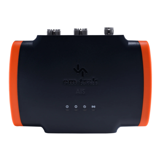
About your AIS class B transceiver 2.8 Mobile app An em-trak mobile app CONNECT-AIS is available for Apple and Android devices from the App store and Google play. 2.9 Transceiver overview indicator lights indicator lights Power and data NMEA 2000... - Page 16 About your AIS class B transceiver 2.9.1 Electrical connections The AIS transceiver has the following electrical connections: ● Power supply ● NMEA0183 data ports for connection to chart plotters or other NMEA0183 compatible equipment ● USB for connection to a PC or Mac ●...
-
Page 17: Installation
3.1 Preparing for Installation Before starting the installation you will need to download the manual and ProAIS2 software from the em-trak website www.em-trak.com/installation. If you have a WiFi and Bluetooth enabled variant you can configure the unit using your mobile phone and CONNECT-AIS, the app available for download from the App Store and Google Play. - Page 18 Installation Please take the time to familiarise yourself with the system elements and their connections prior to attempting installation. GNSS antenna (Optional) VHF antenna Chartplotter AIS Class B transceiver Power in Switch NMEA 2000 NMEA 0183 device Figure 4 Typical installation configuration without antenna splitter...
- Page 19 Installation GNSS antenna VHF radio (Optional) VHF antenna Chartplotter AIS Class B transceiver Power in Switch NMEA 2000 NMEA 0183 device Figure 5 Typical installation configuration with antenna splitter In addition to the items provided with your AIS transceiver the following items may also be required for the installation: 3.1.1...
- Page 20 Installation 3.1.2 VHF antenna Connection to a suitable VHF antenna will be required for the AIS transceiver to receive and transmit. The standard transceiver variants will require an AIS antenna (tuned to 162MHz) for optimum performance. Transceiver/splitter variants will require a broadband antenna (tuned to 159MHz) so it will be compatible with both VHF radio (156MHz) and AIS (162MHz).
- Page 21 Installation for use with AIS devices. Depending on the interfaces supported by your chartplotter, you can connect in the following ways: ● NMEA 0183 - we recommend that 38400 baud is used for outputting AIS data. This is also known as NMEA HS by some manufacturers. ●...
-
Page 22: Installation Procedures
If after reading this manual you are unsure about any element of the installation process please contact your dealer or support@em-trak.com for advice. The following sections explain the installation process step by step for each of the main elements of the system. - Page 23 Installation ● The transceiver should be mounted at least 1m away from sources of interference like VHF radios, transmitting antennas, radar, etc. 43 mm 150 mm 150 mm Figure 6 AIS transceiver dimensions 1. Mount the bracket to the suitable surface using the four self-tapping screws provided.
- Page 24 Installation ™ FLEXI-FIT bracket system Figure 7 AIS transceiver mounting Page 22...
- Page 25 The unit has an internal GNSS antenna. There is also the facility to connect an optional external GNSS antenna, which is available for purchase from em- trak. Please contact support@em-trak for more information. Please note the following guidelines when installing an external GNSS antenna.
- Page 26 Installation B921, B922, B951 and B952 B923, B924, B953 and B954 GNSS antenna GNSS antenna Figure 9 Position of the GNSS antenna connector Step 3 - Connecting the VHF antenna Route the cable from the VHF antenna to the AIS transceiver and connect to the VHF connector on the AIS transceiver as shown in Figure 10.
- Page 27 Installation Step 4 - Connecting the accessory cable An accessory cable is supplied with the product to provide connections to power, the external switch, the NMEA0183 data ports and USB. The cable has a pre-molded connector at one end which should be connected to the connector on the unit marked 'POWER/0183'.
- Page 28 Installation Purple NMEA0183 port 2 Low speed NMEA port (4,800baud) intended for connection to other Pink NMEA0183 port NMEA0183 compatible sen- 2TX- sors for multiplexing of data to the chart plotter Grey NMEA0183 port 2 Yellow NMEA0183 port 2 Table 5 Colour coding of wires in the accessory cable Please check your wiring very carefully before applying power to the product.
- Page 29 Installation Step 5 - Connecting an external switch A toggle switch can be connected to the AIS transceiver to provide remote control of silent mode. Connect the toggle switch between the light green and orange wires as shown in Figure 11. Connection of an external switch to toggle silent mode is optional and not essential for normal operation of the product.
- Page 30 Installation Step 6 - Connection to an NMEA2000 network The AIS transceiver can be connected to an existing NMEA 2000 network to provide AIS and position data to other connected devices such as chartplotters, instruments, sensors, etc. Connection is made by a Micro-C drop cable. This item is not supplied so you will need to purchase one from your local dealer.
- Page 31 USB drivers will need to be installed for Windows operating systems (Windows 7 and up). These are installed automatically by using either Windows Update or when installing proAIS2. proAIS2 is available for download from www.em-trak.com/installation USB drivers are typically not required for MacOS X operating systems. Page 29...
- Page 32 Installation Step 9 - Connecting the VHF radio (applies to splitter variants only) A standard marine band VHF radio can be connected to the splitter variants of the transceiver, so that one VHF antenna can be used for both VHF radio and AIS.
- Page 33 Installation Step 10 - Connecting to a power supply The AIS transceiver requires a 12V or 24V power supply, typically provided by the vessel's battery to operate correctly. It is recommended that crimped and soldered lugs are used to connect the AIS transceiver to the power source via a suitable circuit breaker and/or 3A fuse block.
-
Page 34: Configuring Your Ais Transceiver
2. Configuration using proAIS2 proAIS2 can be used to program your transceiver. This applies to all variants. proAIS2 is available to download from www.em-trak.com/installation If your vessel is registered in the US you are not permitted to program the transceiver yourself. -
Page 35: Introduction To Proais2
The vessel data must only be programmed by a competent installer. If your AIS transceiver has not been pre-configured for you please refer to your dealer or support@em-trak.com for advice on how to have the AIS transceiver configured by a competent installer. -
Page 36: Wifi And Bluetooth Configuration Using Proais2
MMSI correctly. If you need to change the MMSI for any reason, please contact your dealer or support@em-trak.com who for support. 4.6 WiFi and Bluetooth Configuration using ProAIS2 This section applies to AIS transceivers with the WiFi and Bluetooth feature only. - Page 37 Configuring your AIS transceiver ● WiFi network name (the SSID will be blank, any name can be entered by user), ● IP address of the network (e.g. 192.168.0.1) ● Password - Any 8 characters or more. ● WiFi Channel - Preferably 1, 6, or 11). ●...
- Page 38 Configuring your AIS transceiver experience slow connection speeds, signal dropouts or not being able to connect at all. 4.6.4 Line of sight and obstacles For best results, WiFi and Bluetooth products should have a clear, direct line of sight to the transceiver. Any physical obstruction can degrade or even block the signal.
-
Page 39: Configuration Using The Connect-Ais
Configuring your AIS transceiver 4.7 Configuration using the CONNECT-AIS Once CONNECT-AIS is installed on your smart-phone you will need to carry out the following to configure your transceiver: 1. Ensure the AIS transceiver is installed correctly and is powered up by 12 - 24V. -
Page 40: Operation
Operation Operation 5.1 Using the AIS transceiver Once the unit has been configured it is ready for use. Providing other vessels installed with AIS transceivers are within radio range of your vessel you should see their details appear on your chart plotter, PC / laptop or mobile device. -
Page 41: Indicator Functions
Operation Indicator functions The AIS transceiver includes four coloured indicators as shown in Figure 16. The state of the indicators provide information regarding the status of the AIS transceiver. Indicator lights Figure 16 Indicator location on the AIS transceiver unit The meaning of each indicator is shown in the table below Figure 16 shows the indicator positions on the AIS transceiver. - Page 42 Operation Amber indicator The AIS transceiver is not transmitting. This can be for a number of reasons: ● The AIS radio channels are exceptionally busy so there are currently no available slots for transmission. ● The unit has been in silent mode and after deactivating silent mode this amber indicator will illuminate until the first AIS message has been sent ●...
-
Page 43: Voyage Data Recorder
Voyage Data Recorder Voyage Data Recorder This feature is available on AIS transceivers with the WiFi and Bluetooth Features only (B922, B924, B952 and B954). The transceiver will log your own position at regular intervals if your position has changed by more than 10m. Data is stored for 30 days. The VDR log can be retrieved from the VDR tab within proAIS2. -
Page 44: Technical Information
Technical Information Technical Information 7.1 NMEA 2000 PGN List The PGN’s listed in Table 10 are supported by the AIS transceiver. There are no unused fields Title in NMEA database Usage NMEA 0183 (Dec.) (Hex.) 059392 0E800 ISO Acknowledgment in, out 059904 0EA00 ISO Request... - Page 45 1F802 GNSS Direction data 129029 1F805 GNSS Position data 129038 1F80E AIS Class A Position VDM/VDO Report 129039 1F80F AIS Class B Position VDM/VDO Report 129040 1F810 AIS Class B Extended VDM/VDO Position Report 129041 1F811 AIS AtoN Report VDM/VDO...
- Page 46 AIS Addressed SRM VDM/VDO 129802 1FB0A AIS Safety Broadcast VDM/VDO Binary Message 129809 1FB11 AIS Class B CS Static VDM/VDO Data Report Part A 129810 1FB12 AIS Class B CS Static VDM/VDO Data Report Part B Table 10 NMEA 2000 PGN List...
-
Page 47: Troubleshooting
Troubleshooting Troubleshooting Issue Possible cause and remedy No indicators are ● Check that the power supply is connected illuminated correctly. ● Check that the power supply is a 12V or 24V supply. The red error There may be a problem with the VHF antenna sys- tem. - Page 48 Check that there are no obstructions between the transceiver and mobile device ● Check that there are no sources of interference nearby If the guidance given above does not rectify the problem you are experiencing, please contact your dealer or support@em-trak.com for further assistance. Page 46...
-
Page 49: Specifications
Specifications Specifications Parameter Value Dimensions 149 x 118 x 47 mm (L x W x H) Weight Transceiver only variants 380g Transceiver with splitter variants 345g Power DC (9.6V - 31.2V) Average power consumption Transceiver only variants 170mA at 12VDC Transceiver with splitter variants 220mA at 12VDC Peak current rating Transceiver only variants 2A... - Page 50 Specifications VHF Transceiver Transmitter x 1 Receiver x 2 (Receivers time shared between AIS and DSC) Frequency: 156.025 to 162.025 MHz in 25 kHz steps Output Power 33dBm ± 1.5 dB CSTDMA Output Power 37dBm ± 1.5 dB SOTDMA Channel 25kHz Bandwidth Channel Step...
- Page 51 Specifications Page 49...
-
Page 52: List Of Abbreviations
List of abbreviations 10 List of abbreviations Automatic Identification System AIS SART AIS Search and Rescue Transmitter Access Point (Relating to WiFi behaviour) AtoN AIS Aid to Navigation Compact Disc European Declaration of Conformity Course Over Ground Common (electrical) Closest Point of Approach Carrier Sense Direct Current Decimal... - Page 53 List of abbreviations Estimated Time of Arrival External Federal Communications Committee GNSS satellite fault detection message GNSS fix accuracy and integrity message Global positioning system (GPS) fix data message Geographic position - Latitude/longitude message GLONASS Globalnaya Navigazionnaya Sputnikovaya Sistema (Russian GNSS) Electrical Ground GNSS fix data message GNSS...
- Page 54 List of abbreviations Latitude Liquid Crystal Display Longitude Long Range Minimum Keyboard and Display MMSI Maritime Mobile Service Identity Man Overboard Normally Closed (electrical) Navigation Nautical Miles NMEA National Marine Electronics Association Portable Document Format Parameter Group Number Presentation Interface RAIM Receiver Autonomous Integrity Monitoring Radio Equipment Directive...
- Page 55 List of abbreviations Transmission Control Protocol TCPA Time to Closest Point of Approach TDMA Time Division Multiple Access True heading and status message Threaded Neill–Concelman (a type of connector) Threads per Inch Transmit User Datagram Protocol Ultra High Frequency Co-ordinated Universal Time Dual ground/water speed message All VDL AIS messages received AIS own-ship broadcast data...
- Page 56 List of abbreviations Page 54...
- Page 58 Manufacturer’s code: 427 NMEA 2000 Product code: XXXXXX 201-0952:1...
Need help?
Do you have a question about the AIS Class B and is the answer not in the manual?
Questions and answers