Table of Contents
Advertisement
Quick Links
Advertisement
Table of Contents

Subscribe to Our Youtube Channel
Related Manuals for Storz ARTip CRUISE UR500B


Summary of Contents for Storz ARTip CRUISE UR500B
- Page 1 Instructions for use ARTip CRUISE™ UR500B, UR500C...
- Page 2 03-2021 Copyright © All product illustrations, product descriptions, and texts are the intellectual property of KARL STORZ SE & Co. KG. Their use and reproduction by third parties require the express approval of KARL STORZ SE & Co. KG. All rights reserved.
-
Page 3: Table Of Contents
Table of contents Table of contents 1 General information............................ 5 Read the instructions for use ........................ 5 Description of warning messages...................... 5 Open-source software requests ....................... 5 2 Normal use.............................. 6 Intended purpose............................ 6 Indications.............................. 6 Contraindications............................ 6 Target user populations .......................... 6 User qualifications ............................ 6 Target patient groups .......................... 7 Intended conditions of use ........................ 7 3 Safety ................................ 8 Serious incidents ............................ 8... - Page 4 Table of contents Control options for the holding arm...................... 36 Function of the various switches ...................... 36 Visual status displays.......................... 37 Acoustic status displays ......................... 37 Selecting the initial position of the holding arm.................. 37 Controlling the ARTip CRUISE™ with IMAGE1 PILOT ................ 39 Manually controlling the ARTip CRUISE™ ..................... 40 Arm safety lock ............................ 40 Saving a position ............................ 41 6.10 Emergency setting .......................... 43...
-
Page 5: General Information
Designates a possibly harmful situation. If this is not avoided, the products could be damaged. 1.3 Open-source software requests To obtain a copy of the source code being made publicly available by KARL STORZ in connection with the open source software used in this KARL STORZ device, you should send your request, along with the equipment part number and serial number, either via email to opensource@karlstorz.com or by post to... -
Page 6: Normal Use
Intended purpose of the exoscope adaptor for motorized holding arm The exoscope adaptor serves to secure KARL STORZ exoscopes to the motorized holding arm for short-term use in open, microsurgical and minimally invasive interventions. The exoscope adaptor does not come into contact with the patient and is therefore non-invasive. -
Page 7: Target Patient Groups
Normal use – No physical impairments that could diminish perception of activation and alarm signals (visual and acoustic) 2.6 Target patient groups Gender No restriction No restriction Weight No restriction Medical condition Suitable for the treatment, taking into account the indications and contraindications, in the opinion of the physician 2.7 Intended conditions of use The product may only be used in hospitals in suitable ambient conditions. -
Page 8: Safety
Safety 3 Safety 3.1 Serious incidents According to the Medical Device Regulation (MDR), a “serious incident” includes incidents that directly or indirectly had, could have had, or could have any of the following consequences (MDR, Art. 2, No. 65 [1]): – Death of a patient, user, or another person –... -
Page 9: Applied Part, Type Bf
Safety 3.6 Applied part, type BF The ARTip CRUISE™ is a type-BF applied part. If a type CF applied part is combined with a type-BF applied part, this means that the type CF applied part also complies with the limit values of type BF. - Page 10 Safety Activity Text message Optical Acoustic signal signal When the footswitch is ARTip CRUISE™ ac- Illuminated white <Confirmation> pressed, the ARTip CRUISE™ tive acoustic signal can be activated The user puts the AR- ARTip CRUISE™ in Flashing white <In motion> Tip CRUISE™ arm into motion motion acoustic signal by inputting a command...
-
Page 11: Product Description
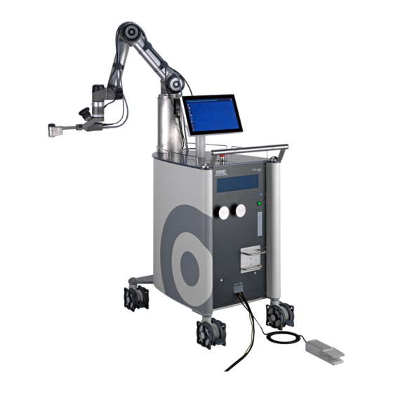
Product description 4 Product description 4.1 Device overview ® VITOM 3D (not included in the scope of 10 Bracket for connecting cable supply) ® VITOM 3D adaptor 11 Power switch Switch for manual mode 12 Earth leakage monitor display field Illuminated ring status display (UFD) 13 Breaker for earth leakage monitor warn- ing signal... -
Page 12: Symbols On The Packaging
Product description 4.2 Symbols on the packaging Symbol Meaning Manufacturer Date of manufacture Serial number Article no. Unsterile Fragile, handle with care Keep away from sunlight Keep dry Air pressure limit Humidity limit Temperature limit Non-ionizing electromagnetic radiation Consult instructions for use Instructions for use •... -
Page 13: Symbols On The Device
Product description Symbol Meaning Medical device CE conformity mark With this mark, the manufacturer declares the compliance of the prod- ucts with the applicable Regulation (EU) 2017/745. A code number after the CE mark indicates the responsible notified body. In accordance with US federal law (21 CFR 801.109), this product may only be sold to or on prescription from a licensed physician. -
Page 14: Possible Combinations
Product description – Ethernet cable 4.5 Possible combinations ATTENTION Incompatible accessory! Malfunctions and damage to the device! Only use the compatible accessories designated by KARL STORZ. Required accessories ® – VITOM 3D adaptor UR 002 Other accessories To enable normal use, the ARTip CRUISE™ requires additional accessories which have their... -
Page 15: Storage And Usage Conditions
Product description Monitor specifications Display size 15.6" Resolution 1366 x 768 Frequency (horizontal) 30–80 kHz Frequency (vertical) 50–75 Hz Contrast ratio 500:1 typical Brightness 300 cd/m Field of view (horizontal/vertical) 160° typical Number of colors 16.7 million IP degree of protection IP 52 DV input 24 VDC Dimensions (W x H x D) - Page 16 Product description – IP degree of protection: IP20 According to IEC 60601-1-2, FCC-B: Please read the Electromagnetic Compatibility information. Directive compliance According to the European Medical Device Regulation (MDR) EU 2017/745: This medical device belongs to Class I The code number after the CE mark indicates the responsible notified body.
-
Page 17: Preparation
Preparation 5 Preparation 5.1 Unpacking the product Carefully remove the product and accessories from the packaging. Check the delivery for missing items and evidence of shipping damage. In the case of damage, hidden defects, and short deliveries, document their nature and extent and contact the manufacturer or supplier immediately. - Page 18 Preparation Lay the wooden ramp onto the front of the pallet. It will be needed later on when removing the ARTip CRUISE™ from the pallet. Removing the side parts The side parts are held together by 3 plastic closures on the front and 3 on the back. Pull the locking tabs upwards and out of the plastic closures.
- Page 19 Preparation Then remove the packaging box at the back. Removing the accessory boxes and foam parts Remove the accessory boxes. The boxes contain the footswitch, the monitor and other accessories. 10. The holding arm is secured with 2 securing straps, one on the cart push handle and one around the entire cart.
-
Page 20: Installing The Monitor
Preparation 14. Then pull the wheel relief board out from under the ARTip CRUISE™ and remove it. Removing the ARTip CRUISE™ from the pallet 15. Lay the wooden ramp onto the front of the pallet. 16. Unlock the brakes on the wheels of the ARTip CRUISE™. 17. -
Page 21: Initial Commissioning
Preparation Connect the 3 cable connectors coming out of the monitor holder to the corresponding ports on the bottom of the monitor. There are 4 screws on the back of the monitor housing. Completely unscrew the two screws at the bottom of the monitor housing using an Allen key and place to the side. Undo the two screws at the top of the monitor housing but do not completely remove them. - Page 22 Preparation As the load-up procedure progresses, the boxes will be filled in. At the end of the charging time (approx. 2.5 minutes), the bar will disappear automatically. The buttons are still inactive after starting (grayed out). To activate the boxes, press the footswitch or release button until the activation bar is full and has automatically disappeared.
- Page 23 Preparation Press the Transport button in this submenu. Another submenu will appear. Press the 1st time Setup position button. Instructions for use • ARTip CRUISE™ • YDZ702_EN_V1.0_03-2021_IFU_CE-MDR...
-
Page 24: Installing The Vitom 3D Adaptor
Preparation Follow the instructions on the touchscreen. When the arm is moving, keep the release button pressed down until a message appears confirming that the position has been reached. Never release the button before this message appears, as otherwise the arm will remain ®... -
Page 25: Setting Up The Device
Preparation 5.6 Setting up the device The equipment may only be used in medical rooms with electrical systems that have been installed in accordance with applicable national regulations. ATTENTION Blocked air inlets! Damage to the device! Blocked air inlets can cause the device to fail and can pose a risk of fire due to overheating. Remove any blockages in the air inlets when setting up the device. -
Page 26: Operation With Hf Surgical Equipment
Preparation Insert the connecting cable for the footswitch into the corresponding serial port Place the cable into the recess on the cable hatch and close the cable hatch. If not already connected, connect the illuminated ring (UFD) to the connection on the holding arm base using the connecting cable. - Page 27 Preparation ð The buttons are now active. The monitor is a touchscreen monitor. On the left-hand side of the user interface are various options that can be activated by tapping with the finger. The buttons are drop-down menus that either open up further options or provide instructions. The following actions can be triggered from the start menu: Instructions for use •...
-
Page 28: Placing The Vitom ® 3D Into The Holding Arm
Preparation Drape Position: Moves the arm to a suitable position in order to attach instruments and sterile drapes Start Position: Allows the ARTip CRUISE™ to be positioned to the left or right of the patient Standby Position: Allows the holding arm to be moved out of the operating field during the procedure Save current Position: Saves the current position of the holding arm Saved position: Moves the holding arm to the saved position... -
Page 29: Securing Cables To The Holding Arm
Preparation ® ® Place the VITOM 3D in the clamp on the VITOM 3D adaptor. There is a groove on the ® bottom of the VITOM 3D (see detail image). The groove must engage in the ridge on the base of the open clamp. Close the clamp. -
Page 30: Configuring The Touchscreen Settings
Preparation 5.12 Configuring the touchscreen settings Various settings can be made via an OSD (Onscreen Display) menu on the touchscreen. The buttons for the OSD are located on the back of the monitor. The buttons have the following functions: – POWER: switch the monitor on/off –... - Page 31 Preparation Press the MENU button on the back of the monitor. ð The sub-items Backlight, Brightness, Contrast and Sharpness appear in the bottom row of the OSD menu. Use the UP/DOWN buttons on the back of the monitor to select the Backlight menu item.
-
Page 32: Attaching The Image1 Pilot
5.13 Attaching the IMAGE1 PILOT The IMAGE1 PILOT is equipped with a KSLOCK interface (male) on its underside for easy attachment to KARL STORZ articulated stands. Position the IMAGE1 PILOT over the KSLOCK interface. Insert the KSLOCK interface of the IMAGE1 PILOT into the KSLOCK interface on the holding system. -
Page 33: Attaching A Sterile Drape To The Artip Cruise
WARNING Risk of infection: Sterility has only been validated with the VITOM® 3D when using the KARL STORZ drape with Art. no. TH 001. Do not use any other drapes. On the touchscreen, press the <Drape Position> button and press and hold the release button until the POSITION REACHED message appears. - Page 34 Preparation Remove the drape from the sterile packaging. Starting with the distal end, insert the ® VITOM 3D into the slightly projecting part of the drape marked with an arrow. ® Pull the plastic housing as far as it will go over the distal part of the VITOM There are end stops in the plastic housing which prevent the housing being pulled too far ®...
-
Page 35: Attaching A Sterile Drape To The Image 1 Pilot
Preparation ® Attach the drape to the VITOM 3D and holding system using the tightening straps. Make sure that there is enough space for the arm to move freely. Carefully remove the tightening straps from the drape in the direction of the arrow. If too much force is applied when pulling, the sheet can become detached from the plastic housing or the drape may tear. -
Page 36: Operation
Operation 6 Operation 6.1 Control options for the holding arm There are three different ways of changing the position of ARTIP CRUISE™ holding arm: – Use the touchscreen and release button for initial positioning before surgery begins. – Use the IMAGE1 PILOT and the footswitch for positioning for precise image control. –... -
Page 37: Visual Status Displays
Operation 6.3 Visual status displays The illuminated ring status display provides information on the system's operating and error states. – Illuminated white: equipment ready, arm can be moved – Flashing white: arm is being moved – Flashing green for approx. 3 seconds: the current position has just been saved –... - Page 38 Operation Press the relevant button. ð The selected position is displayed on the touchscreen. ð The message ‘Press activation-button to move ARTip’ appears on the touchscreen. Press the release button. ð The ARTip CRUISE™ moves to the preselected position. ð When the start position is reached, a corresponding message is shown on the touchscreen.
-
Page 39: Controlling The Artip Cruise™ With Image1 Pilot
Operation 6.6 Controlling the ARTip CRUISE™ with IMAGE1 PILOT The ARTip CRUISE™ holding arm can be moved using the 3D wheel of the IMAGE1 PILOT together with the footswitch. ð If the footswitch is not actuated, the control commands of the 3D wheel only apply to ®... -
Page 40: Manually Controlling The Artip Cruise
Operation – Tilting the 3D wheel (in all directions) changes the field of view around the center point of the image in the site. It may be useful to activate a pointer in the IMAGE1 S to emphasize the modified field of view around the center point. 6.7 Manually controlling the ARTip CRUISE™... -
Page 41: Saving A Position
Operation It is possible to activate the arm without the system restore. To do so, press and hold the footswitch or the release button until the activation bar is full. The arm moves briefly and minimally during activation. 6.9 Saving a position Only one position can be saved. - Page 42 Operation Press the footswitch and key 1 or 2 on the IMAGE1 PILOT for 2 seconds. ð The current position of the ARTip CRUISE™ holding arm is saved. ð A corresponding message is displayed on the operation screen. Recalling the saved position Press the footswitch and key 3 or 4 on the IMAGE1 PILOT.
-
Page 43: Emergency Setting
Operation Recalling the saved position Press the Saved position button ð The message ‘Press activation-button to move ARTip’ appears on the touchscreen. Press the release button ð The saved position is automatically recalled. The release button must be held down until the final position has been reached. Releasing the release button stops the movement of the arm. -
Page 44: System Setup
Operation – Upon pressing the emergency stop switch, movement of the holding arm is immediately blocked and the entire system is deactivated. – The message ‘Release emergency stop switch’ appears on the touchscreen Resetting the emergency stop switch Turn the red button on the emergency stop switch in a clockwise direction. ð... - Page 45 Operation Monitor calibration A maladjusted touchscreen can be calibrated again using the calibration function. Press the Monitor Calibration button. ð A circle with a crosshair appears on the monitor, together with the message ‘Touch the center of the circle’. Touch the center of the circle with your finger. Three more circles will then appear in the other corners of the monitor.
- Page 46 Operation – Screen: acoustic signal when screen inputs are being made – Enabling devices: acoustic confirmation signal when the footswitch and release button are activated Adjust the volume by tapping the + or – buttons. Alternatively, the volume can be adjusted by touching and moving within the number field between the ±...
- Page 47 Operation Alternatively, the speed can be adjusted by touching and moving within the number field between the ± buttons. Language The language in which the screen contents are shown can be selected in the Language menu. To select the language, tap on the button for the preferred language. System information The following information about the ARTip CRUISE™...
- Page 48 Data logging The following can be carried out in the Data Logging menu... – Reading of data logs. This function is only available for authorized KARL STORZ service personnel – Reading of error logs on a USB stick. This function is also available for the user.
- Page 49 Operation 11. Press the 'Copy Log Data' button. 12. On completion of the procedure, a corresponding message appears. Remove the USB stick. Transport The ARTip CRUISE™ holding arm cam be moved to a position for the safe transportation of the system in the Transport menu. 13.
- Page 50 Operation 14. Press the Transport Position button. ð A message appears on the touchscreen explaining that the monitor needs to be rotated by 90° before arm movement can be activated. 15. Move the monitor to the corresponding position and activate the arm movement by pressing the release button.
- Page 51 Operation 1st time setup position The 1st time Setup Position button can be used to move the holding arm from the transport position to a working position. This procedure is described in detail in the Initial commissioning section. Instructions for use • ARTip CRUISE™ • YDZ702_EN_V1.0_03-2021_IFU_CE-MDR...
-
Page 52: Reprocessing
When preparing and using solutions, follow the chemical manufacturer's instructions concerning concentration, exposure time and service life. CAUTION Damage to the device! Only perform reprocessing using chemicals approved by KARL STORZ. A list of approved chemicals can be requested from hygiene@karlstorz.com. CAUTION National laws and regulations must be observed. -
Page 53: Manual Wipe-Down Disinfection
Reprocessing 7.2 Manual wipe-down disinfection Wipe-clean the exterior surfaces of the medical device with a disposable cloth moistened with disinfectant or a ready-to-use soaked disinfectant cloth. Due to their protein-fixating effect and possible material incompatibility, alcohol-based agents must not be used. The chemical manufacturer's specifications regarding material compatibility must be observed. -
Page 54: Maintenance, Repair, And Disposal
Make sure that the connection to the power supply is disconnected. Request a KARL STORZ service technician for service work. Defective equipment must be serviced and repaired by authorized KARL STORZ personnel only. Only parts approved by KARL STORZ may be used. After the repair, have an electrician carry out and record a safety check in accordance with IEC 62353. -
Page 55: Repairing Products
In other countries, the respective KARL STORZ branches or specialist dealers are responsible. 8.4 Infection prevention Contaminated products may not be shipped. To prevent contact infections and airborne infections, devices must first be decontaminated. KARL STORZ reserves the right to send back contaminated devices. 8.5 Disposing of the product The product meets the requirements of the Directive on Waste Electrical and Electronic Equipment (WEEE). -
Page 56: Accessories And Spare Parts
Accessories and spare parts 9 Accessories and spare parts 9.1 Spare parts Article number Description 1496195 ARTIP CRUISE™ outlet filter (bottom) 1496295 ARTIP CRUISE™ inlet filter (top) 1508095 ARTIP CRUISE™ rubber for cable guide 1901995 ARTIP CRUISE™ EU power cord 1902095 HIVE network cable, 5 m 1902195... -
Page 57: Electromagnetic Compatibility
Electromagnetic compatibility 10 Electromagnetic compatibility 10.1 General notes on the operating environment The product is suitable for use in professional healthcare settings. Professional healthcare facilities include physician offices, dental offices, limited care facilities, freestanding surgical centers, freestanding birth centers, multiple treatment facilities, hospitals (emergency rooms, patient rooms, intensive care, surgical rooms, outside the HF-shielded room of an ME system for MRT). - Page 58 Electromagnetic compatibility Interference im- EN/IEC 60601 test Compliance level Electromagnetic envi- munity tests level ronment – guidelines 100 kHz repetition 100 kHz repetition Surges acc. to ± 1 kV voltage outer ± 1 kV voltage outer The power supply qual- IEC 61000-4-5 conductor – outer con- conductor –...
- Page 59 Electromagnetic compatibility 10.3 Table 2 – Test levels for proximity fields from HF wireless communications equipment Test fre- Frequency Radio service Modulation Immunity Compliance quency band test level level 380 – 390 TETRA 400 Pulse modula- tion 18 Hz 430 – 470 GMRS 460, FM ± 5 kHz FRS 460...
- Page 60 Electromagnetic compatibility Interference immunity EN/IEC 60601 test Compliance Electromagnetic envi- tests level level ronment – guidelines Radiated HF distur- 3 V/m 3 V/m product, including cables, bances acc. to IEC than the recommended 80 MHz to 2.5 GHz 61000-4-3 separation distance calcu- lated from the equation applicable to the fre- quency of the transmitter.
- Page 61 Electromagnetic compatibility 10.5 Table 4 – Emission class and group Guidelines and manufacturer’s declaration – electromagnetic emissions The device is intended for use in such an environment as specified below. The customer or user of the device should ensure that it is used in such an environment. Interference emission measure- Compliance Electromagnetic environment –...
-
Page 62: Appendix
Appendix 11 Appendix 11.1 Dimension sketches All dimensions in mm Instructions for use • ARTip CRUISE™ • YDZ702_EN_V1.0_03-2021_IFU_CE-MDR... - Page 63 Appendix Instructions for use • ARTip CRUISE™ • YDZ702_EN_V1.0_03-2021_IFU_CE-MDR...
- Page 64 Appendix Instructions for use • ARTip CRUISE™ • YDZ702_EN_V1.0_03-2021_IFU_CE-MDR...
- Page 65 Appendix Instructions for use • ARTip CRUISE™ • YDZ702_EN_V1.0_03-2021_IFU_CE-MDR...
-
Page 66: Subsidiaries
KARL STORZ Veterinary Endoscopy-America, Inc. Email: info-be@karlstorz.com 1 South Los Carneros Road, Goleta, CA 93117, USA KARL STORZ Endoscopie France S. A. S. Phone: +1 805 968-7776, Fax: +1 805 685-2588 12, rue Georges Guynemer, Quartier de l’Europe, 78280 Guyancourt, France Email: info@karlstorzvet.com... - Page 67 No. 8 Commonwealth Lane #03-02, Singapore 149555, Singapore Phone: +65 69229150, Fax: +65 69229155 KARL STORZ ENDOSKOPE – East Mediterranean and Gulf (Offshore) S.A.L. Email: infoasia@karlstorz.com Spark Tower 1st floor Charles Helou St., Horch Tabet – Sin El Fil, Beirut,...
- Page 68 KARL STORZ SE & Co. KG Dr.-Karl-Storz-Straße 34 78532 Tuttlingen Postfach 230 78503 Tuttlingen Germany Phone: +49 7461 708-0 Fax: +49 7461 708-105 E-mail: info@karlstorz.com www.karlstorz.com...
Need help?
Do you have a question about the ARTip CRUISE UR500B and is the answer not in the manual?
Questions and answers