
Related Manuals for Quick CHC 1202 M


Summary of Contents for Quick CHC 1202 M
- Page 1 REV 005 High Quality Nautical Equipment CHAIN COUNTER CHC 1202 M ALLARME SALITA VELOCITA' 000 M/M Manuale d'uso CONTA CATENA CHC 1202 M User's Manual CHAIN COUNTER CHC 1202 M...
- Page 2 INDICE Pag. 4 CARATTERISTICHE E INSTALLAZIONE Pag. 5 INSTALLAZIONE - Installazione del sensore giri Pag. 6 INSTALLAZIONE - Installazione del magnete - Installazione del sensore Pag. 7 INSTALLAZIONE - Installazione dello strumento Pag. 8 INSTALLAZIONE - Installazione a pannello - Installazione a retro pannello Pag.
- Page 3 INDEX Pag. 32 CHARACTERISTICS AND INSTALLATION Pag. 33 INSTALLATION - Installing the laps sensor Pag. 34 INSTALLATION - Installing the magnet - Installing the sensor Pag. 35 INSTALLATION - Installing the chain counter Pag. 36 INSTALLATION - Panel-mounting - Installing the chain counter behind the panel Pag.
- Page 4 La lunga esperienza maturata nel settore della nautica ci ha permesso di evolvere lo strumento conta catena, ora denominato CHC 1202 M, confermando prestazioni superiori rispetto allo standard di mercato. Lo strumento CHC 1202 M permette di azionare il salpa ancora, per salpare o calare l'ancora, fornendo la misura della catena calata.
-
Page 5: Installazione
Tutti i salpa ancora Quick sono già dotati, di serie, del sensore giri adatto per l'utilizzo con lo strumento conta catena CHC 1202 M. Altri salpa ancora Lo strumento conta catena, per poter misurare la lunghezza di catena calata, deve contare il numero di giri che compie l'ingranaggio che muove la catena (barbotin). -
Page 6: Installazione Del Magnete
INSTALLAZIONE INSTALLAZIONE DEL MAGNETE Smontare il barbotin dal salpa ancora (riferirsi al manuale d'uso del salpa ancora). Individuare la posizio- ne più adatta dove praticare la sede per alloggiare il magnete seguendo questi criteri: • La sede deve essere praticata in una zona non interessata dal passaggio della catena (zone esterne). •... - Page 7 INSTALLAZIONE INSTALLAZIONE DELLO STRUMENTO Di seguito sarà descritta una procedura di installazione tipica. Non è possibile descrivere una procedura che sia applicabile a tutte le situazioni. Adattare questa procedura per soddisfare i propri requisiti. Individuare la posizione più adatta dove praticare la sede per alloggiare lo strumento seguendo questi criteri: •...
- Page 8 INSTALLAZIONE Installazione a pannello Dopo aver scelto dove posizionare lo strumento, proce- dere come riportato di seguito: • Posizionare la dima di foratura (fornita in dotazione) sulla superficie dove sarà installato lo strumento. • Marcare il centro di ogni foro. •...
-
Page 9: Collegamento Elettrico
INSTALLAZIONE COLLEGAMENTO ELETTRICO Lo strumento conta catena risponde agli standard EMC (compatibilità elettromagnetica) ma è richiesta una corretta installazione per non compromettere le proprie prestazioni e quelle degli strumenti posti nelle vicinanze. Per questo motivo i cavi dello strumento devono essere distanti almeno: •... - Page 10 INSTALLAZIONE INSTALLAZIONE DEI TERMINATORI Per far funzionare correttamente la trasmissione dati tra più strumenti conta catena è indispensabile l'installazione dei terminatori (150 ohm). Il terminatore deve essere collegato tra i segnali CANH e CANL del primo e dell'ultimo strumento che compongono la rete, come mostrato nel seguente schema: STRUMENTI DA 5 A 16...
- Page 11 ATTENZIONE: Se uno degli strumenti installati è dotato di una versione software V2.9x o superiore è opportuno aggiornare anche gli altri strumenti alla versione V2.9x o superiore. In caso di dubbi contattare il rivenditore o il servizio clienti Quick ®...
-
Page 12: Funzionamento Dello Strumento
FUNZIONAMENTO DELLO STRUMENTO FUNZIONAMENTO DELLO STRUMENTO L'interfaccia tra l'utente e lo strumento avviene grazie a tre elementi: IL DISPLAY GRAFICO, LA PULSANTIERA E L'AVVISATORE ACUSTICO (BUZZER). Sul display grafico sarà visualizzata la misura della catena calata, lo stato dello strumento ed altre informazioni. La pulsantiera è... - Page 13 FUNZIONAMENTO DELLO STRUMENTO AZIONAMENTO ELETTRICO DEL SALPA ANCORA Salpare l'ancora SALITA Per salpare l'ancora premere il pulsante (UP). Tenere premuto il pulsante fino a che l'ancora non raggiunge la posizione desiderata dopodiché rilasciare VELOCITA' 20 M / M il pulsante. Durante la fase di risalita lo strumento mostrerà una finestra simile a questa: E' possibile salpare l'ancora anche utilizzando un comando elettrico ausiliario;...
- Page 14 FUNZIONAMENTO DELLO STRUMENTO Caduta libera dell'ancora In certe situazioni può essere necessario calare l'ancora sfruttando la possibilità del salpa ancora di fare scendere l'ancora per gravità (senza comando elettrico). Anche in questa situazione lo strumento conta catena misurerà la lunghezza di catena calata. Durante la fase di caduta libera lo strumento mostrerà...
- Page 15 IMPOSTAZIONI DELLO STRUMENTO IMPOSTAZIONI DELLO STRUMENTO Lo strumento conta catena è dotato di varie funzioni personalizzabili a seconda IMPOSTAZIONI delle particolari esigenze dell'utente. AZZERA MISURA FUNZIONI IMPOSTAZ PERS Per entrare nel menù di impostazione è necessario premere e rilasciare il DATA E ORA LINGUA CALIBRAZIONE...
- Page 16 IMPOSTAZIONI DELLO STRUMENTO Nel caso in cui si stia operando su di uno strumento SLAVE con il MASTER non presente sulla rete CAN, sarà mostrato il seguente menù impostazioni "ridotto": IMPOSTAZIONI Questi sotto menù contengono parametri o funzioni particolari per ogni IMPOSTAZ PERS singolo conta catena non condivise in rete con gli altri strumenti.
- Page 17 ATTENZIONE: l'allarme in salita funziona esclusivamente se la salita dell'ancora è comandata da uno strumento conta catena CHC 1202 M. Non funziona se la salita è comandata da un qualsiasi altro comando ausiliario. ATTENZIONE: lo strumento conta catena non è in grado compensare l'inerzia meccanica del salpa ancora (il barbotin può...
- Page 18 IMPOSTAZIONI DELLO STRUMENTO MENU' IMPOSTAZIONE - FUNZIONI - DISCESA AUTOMATICA Tramite questa opzione si imposta o si disattiva la funzione di calata automatica. Questa funzione consente di calare l'ancora in maniera automatica alla profondità impostata (vedi capitolo FUNZIONAMENTO DELLO STRUMENTO paragrafo DISCESA AUTOMATICA). ATTENZIONE: lo strumento conta catena non è...
- Page 19 IMPOSTAZIONI DELLO STRUMENTO MENU' IMPOSTAZIONI - IMPOSTAZIONI PERSONALI CONTRASTO Tramite questa opzione si regola il livello di contrasto dell'LCD. La modifica del livello è applicata immediatamente alla selezione del CONTRASTO valore, senza che il valore sia confermato. IMPOSTA VALORE: i valori selezionabili sono: 1, 2, 3, 4, 5, 6, 7, 8 (imp. di fabbrica: 4). Passa al valore superiore Passa al valore inferiore Conferma il valore e ritorna al menù...
- Page 20 IMPOSTAZIONI DELLO STRUMENTO MENU' IMPOSTAZIONI - IMPOSTAZIONI PERSONALI SUONO TASTI Tramite questa opzione si attiva o disattiva l'avviso sonoro ad ogni SUONO TASTI pressione dei pulsanti. IMPOSTA VALORE: I valori selezionabili sono: SI e NO (imp. di fabbrica: SI). Selezionano i valori disponibili Conferma il valore e ritorna al menù...
- Page 21 IMPOSTAZIONI DELLO STRUMENTO MENU' IMPOSTAZIONI LINGUA Tramite questa opzione è possibile selezionare la lingua dei messaggi di LINGUA sistema. ENGLISH ITALIANO Il sotto menù relativo all'opzione di LINGUA è il seguente: FRANCAIS DEUTSCH ESPANOL Selezionano le voci Conferma il valore e ritorna al menù IMPOSTAZIONI. MENU' IMPOSTAZIONI CALIBRAZIONE Tramite questa opzione è...
- Page 22 IMPOSTAZIONI DELLO STRUMENTO MENU' IMPOSTAZIONI - CALIBRAZIONE - GIRO BARBOTIN Tramite questa opzione si imposta la misura di catena che è svolta ad ogni giro del barbotin. Per ottenere questo valore è necessario smontare il barbotin del salpa ancora, e misurare la lunghezza di catena che può...
- Page 23 IMPOSTAZIONI DELLO STRUMENTO MENU' IMPOSTAZIONI - CALIBRAZIONE CADUTA LIBERA AUTOMATICA Tramite questa opzione si imposta il tempo necessario al sistema di CADUTA LIBERA caduta libera automatica del salpa ancora per disattivarsi. IMPOSTA VALORE: I valori selezionabili sono: DISATTIVATO, da 0.1s a 7s. 0.5 s (imp.
- Page 24 IMPOSTAZIONI DELLO STRUMENTO MENU' IMPOSTAZIONI - CALIBRAZIONE AUTOMATICA Tramite questa opzione è possibile effettuare la calibrazione automatica dello strumento. La prima finestra relativa all'opzione CALIBRAZIONE AUTOMATICA è la seguente: CALIBRAZ AUTOM IMPOSTA VALORE: Tramite questa opzione si seleziona l'unità di misura relativa alla misura METRI PIEDI di catena calata.
- Page 25 IMPOSTAZIONI DELLO STRUMENTO CONTROLLI MENU' IMPOSTAZIONI TEST SENSORE CONTROLLI TEST LCD BATT OROLOGIO Tramite questa opzione si hanno a disposizione delle procedure di VERSIONE SW controllo per verificare la funzionalità dello strumento. DATI FABBRICA CONTROL FLASH Il sotto menù relativo all'opzione CONTROLLI è il seguente: CONTROLLI VERSIONE SW DATI FABBRICA...
- Page 26 IMPOSTAZIONI DELLO STRUMENTO MENU' IMPOSTAZIONI - CONTROLLI VERSIONE SW Questa funzione permette di visualizzare la versione del software VERSIONE SW installata sull'apparecchio. VERSIONE SW VX.X Ritorna al menù CONTROLLI MENU' IMPOSTAZIONI - CONTROLLI DATI FABBRICA Questa funzione permette di impostare i valori dei vari parametri come definiti da fabbrica ed effettua un RESET dello strumento.
- Page 27 IMPOSTAZIONI DELLO STRUMENTO MENU' IMPOSTAZIONI - CONTROLLI CONTROLLO EEPROM (MEMORIA DATI) Questa funzione visualizza il checksum della memoria EEPROM calcolato CONTROL EEPROM (SOMMA) e quello memorizzato (VERO). CONTROL EEPROM VERO: XXXX SOMMA: YYYY Per un corretto funzionamento dello strumento i valori devono coincidere. Ritorna al menù...
- Page 28 Nel caso in cui dovesse comparire una di queste segnalazioni non utilizzare lo strumento e contattare al ® più presto un punto assistenza o il servizio clienti QUICK Errore Multi Master Se lo strumento rileva la presenza di più strumenti MASTER nella rete CAN, MULTI MASTER si avrà...
- Page 29 PROBLEMI DI SISTEMA MASTER assente MANCA MASTER Il problema è segnalato se nella rete CAN non è presente uno strumento con priorità MASTER (vedi capitolo STRUMENTI MULTIPLI). Verificare se lo strumento MASTER è acceso o il cablaggio della linea dati. In presenza del problema è...
- Page 30 PROBLEMI DI SISTEMA PROBLEMI CON RESET MANUALE Il reset di questi problemi avviene con una specifica azione dell'utente: pressione del pulsante (SELECT) o spegnimento e riaccensione dello strumento. In presenza del problema i pulsanti (UP, DOWN) sono disattivati. ALLARM SALITA Allarme in salita Il problema è...
-
Page 31: Manutenzione
Pulire lo strumento con un panno morbido inumidito di acqua. Non utilizzare prodotti chimici o abrasivi per pulire lo strumento. CARATTERISTICHE TECNICHE MODELLO CHC 1202 M CARATTERISTICHE DI USCITA Portata in corrente dei contatti UP/DOWN 4A max Connessioni esterne... - Page 32 1202 M whose performance is widely superior to those of similar instruments available on today's market. The chain counter CHC 1202 M allows the windlass to be activated to get the anchor aweigh or lower the anchor providing the exact measure of the chain lowered.
-
Page 33: Installation
All Quick ® windlasses come with a laps sensor suitable for use with chain counter CHC 1202 M. Other windlasses In order for the chain counter to measure the exact length of the chain, it has to count the number of rev- olutions completed by the gear that drives the chain (gypsy). -
Page 34: Installing The Magnet
INSTALLATION INSTALLING THE MAGNET Take the gypsy off the windlass (consult the user's manual that deals with the windlass). Find the spot most suitable for the magnet housing based on the following criteria: • The magnet should not be installed in an area that the chain passes through (outer areas). •... -
Page 35: Installing The Chain Counter
INSTALLATION INSTALLING THE CHAIN COUNTER The standard installation procedure is described below. Unfortunately we cannot describe a procedure applicable to all types of windlasses. Adapt this procedure to satisfy your own individual requirements. Find the spot most suitable for the chain counter based on the following criteria: •... - Page 36 INSTALLATION Panel-mounting Once the mounting position has been selected, follow the directions given below: • Place the drill template (provided) on the surface where the chain counter will be installed. • Mark the center of each hole. • Drill the holes for the stud bolts with a 5 mm twisted drill.
-
Page 37: Electric Connections
INSTALLATION ELECTRIC CONNECTIONS The chain counter meets standard EMC (electromagnetic compatibility). In any case correct installation is fundamental in order not to affect its performance or interfere with operation of instruments found near it. For this reason the chain counter must be at least: •... - Page 38 INSTALLATION INSTALLING THE TERMINALS In order for data to be correctly transmitted when several chain counters are employed, terminator (150 ohm) must be installed. The terminator should be connected between signals CANH and CANL of the first and last chain counter included in the network, as illustrated in the figure below: INSTRUMENTS FROM 5 TO 16...
- Page 39 WARNING: If any of the instruments installed has a V2.9x version of the software or a more recent release, also the other instruments should be updated to the V2.9x version or the said later release. ® If in doubt, contact your nearest dealer or Quick customer service. CHC1202M IT GB - REV005B...
-
Page 40: Main Window
CHAIN COUNTER OPERATION CHAIN COUNTER OPERATION Three elements are employed between user and counter interface: A GRAPHIC DISPLAY SCREEN, CONTROL KEYS AND BUZZER. The display screen shows the measure of chain lowered, state of the chain counter along with other information. The control panel comes with three keys. - Page 41 CHAIN COUNTER OPERATION WINDLASS ELECTRIC DRIVE CHAIN UP Getting the anchor aweigh To get the anchor aweigh press key (UP). Hold the key pressed until the anchor reaches the desired position and then release it. SPEED 82 M / M While moving up, the chain counter displays a window similar to the one shown below: It is also possible to get the anchor aweigh with an other electric control.
- Page 42 CHAIN COUNTER OPERATION Free fall At times the anchor may have to be lowered by wanting the windlass to free fall (without electrical com- mand). The chain counter will measure the length of the chain lowered under these circumstances as well. A win- dow similar to the one shown below appears during free fall: FREE FALL SPEED...
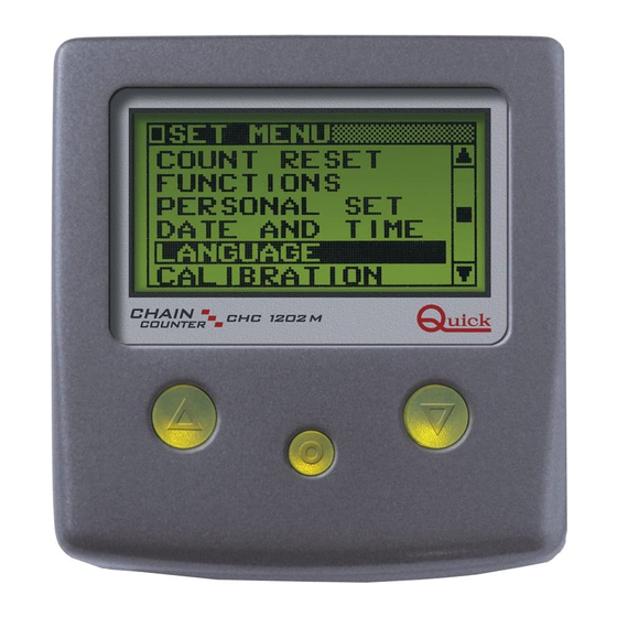
- Page 43 SETTING THE CHAIN COUNTER SETTING THE CHAIN COUNTER The chain counter has a several functions that can be personalized to satisfy SETTINGS user's requirements. To go to the setting menu, press and release key = COUNTER RESET FUNCTIONS PERSONAL SET (SELECT) for more than 3 seconds.
-
Page 44: Settings Menu Functions
SETTING THE CHAIN COUNTER If a SLAVE chain counter is being used without the MASTER in the CAN network, the following "reduced" settings menu will be displayed: SETTINGS These submenus have particular parameters and functions for every PERSONAL SET single counter which can not be shared with other chain counters UTILITY CAN CONFIG present on the CAN network. - Page 45 ATTENTION: the up alarm function is active only by using a chain counter CHC 1202 M controls when the anchor moves up. It does not function if the anchor is moved up by any other remote control or a switch.
- Page 46 SETTING THE CHAIN COUNTER SETTINGS MENU - FUNCTIONS - AUTOMATIC DOWN The automatic down function is enabled or disabled with this option. This function allows the anchor to automatically move down to the set depth (see chapter CHAIN COUNTER OPERATION paragraph AUTO- MATIC DOWN FUNCTION).
- Page 47 SETTING THE CHAIN COUNTER SETTINGS MENU - PERSONAL SET CONTRAST Use this option to adjust the contrast of the LCD. The change is imme- CONTRAST diately made without having to confirm the value. SET VALUE: Selectable values: 1, 2, 3, 4, 5, 6, 7, 8. (default: 4). Increase Decrease Confirm value and go back to PERSONAL SET menu.
- Page 48 SETTING THE CHAIN COUNTER SETTINGS MENU - PERSONAL SET KEY BEEP Use this option to activate or deactivate the beep that sounds when- KEY BEEP ever a key is pressed. SET VALUE: Selectable options: YES and NO. (default: YES). Select the values available. Confirm value and go back to PERSONAL SET menu.
- Page 49 SETTING THE CHAIN COUNTER SETTINGS MENU LANGUAGE Use this option to select the language in which the system messages LANGUAGE are displayed. ENGLISH ITALIANO The LANGUAGE sub-menu appears as shown below. FRANCAIS DEUTSCH ESPANOL Select the data items. Confirm value and go back to SETTINGS menu. SETTINGS MENU CALIBRATION CALIBRATION...
- Page 50 SETTING THE CHAIN COUNTER SETTINGS MENU - CALIBRATION - GYPSY LAP Use this option to set the measurement of the chain in one gypsy lap. To obtain this value, remove the gypsy, wind the chain around it and then measure its length. Consult the User's manual of the windlass for more detailed...
- Page 51 SETTING THE CHAIN COUNTER SETTINGS MENU - CALIBRATION AUTO FREE FALL Through this management we set the time required by the windlass FREE FALL auto free fall system to deactivate itself. SET VALUE: Select the available values: OFF, from 0.1s to 7s. (default: OFF) 0,5 s Increase Decrease...
-
Page 52: Number Of Magnets
SETTING THE CHAIN COUNTER SETTINGS MENU - AUTOMATIC CALIBRATION Use this option to automatically calibrate the chain counter. The first window regarding AUTOMATIC CALIBRATION is shown below: AUTO CALIBRATE SET VALUE: Use this option to select the unit of measurement used to measure the METERS FEET chain lowered. - Page 53 SETTING THE CHAIN COUNTER UTILITY SETTINGS MENU SENSOR TEST UTILITY LCD TEST CLOCK BATTERY This option allows the user to perform procedures to check and control SW VERSION the chain counter operation. SET DEFAULT CHECK FLASH The UTILITY sub-menu appears as shown below: UTILITY SW VERSION SET DEFAULT...
- Page 54 SETTING THE CHAIN COUNTER SETTINGS MENU - UTILITY SW VERSION This function displays the software version installed in the chain counter. SW VERSION SW VERSION VX.X Go back to UTILITY menu. SETTINGS MENU - UTILITY SET DEFAULT This function allows the user to enter the default values and restart the chain counter.
- Page 55 SETTING THE CHAIN COUNTER SETTINGS MENU - UTILITY CONTROL EEPROM (DATA MEMORY) This function shows the calculated EEPROM memory checksum (SUM) CHECK EEPROM and the one stored (TRUE). CHECK EEPROM In order for the chain counter to operate properly the two values must TRUE: XXXX match.
- Page 56 SUM: YYYY FLASH memory checksum error EEPROM memory checksum error If one of these messages appears do not use the chain counter and contact a service center or QUICK ® customer service without delay. Multi Master error If the chain counter detects more then one of MASTER chain counters in...
- Page 57 SYSTEM ERRORS AND FAULT No MASTER NO MASTER This fault is displayed if there is not a chain counter with MASTER priority in the CAN network (see chapter MULTIPLE CHAIN COUNTERS). See if the MASTER chain counter is on and the data line connections. The window shown below appears when this problem is present: SPEED 0 M / M...
-
Page 58: Confirmation Messages
SYSTEM ERRORS AND FAULT PROBLEMS WITH MANUAL RESET These problems are reset by the user: by pressing key (SELECT) or turn off the chain counter and turn it back on. If the fault is present keys (UP, DOWN) are disabled. UP ALARM Up alarm This fault is displayed if the length of the chain is less than the value set on... -
Page 59: Maintenance - Technical Data
Clean the chain counter with a soft rag dampened in water. Do not use chemicals or harsh products to clean the chain counter. TECHNICAL DATA MODEL CHC 1202 M OUTPUT CHARACTERISTICS UP/DOWN contacts current 4A max External connections... - Page 60 CHC 1202 M - DIMENSIONI / DIMENSIONS (mm) CONTACATENA / CHAIN COUNTER COPERCHIO / COVER CHC1202M IT GB - REV005B...
- Page 61 SCHEMA ELETTRICO DEI COLLEGAMENTI THE WIRING DIAGRAM CHC1202M IT GB - REV005B...
- Page 62 NOTES...
- Page 63 NOTES...
- Page 64 R005 Codice e numero seriale del prodotto Product code and serial number ® QUICK SRL - Via Piangipane, 120/A - 48100 Piangipane (RAVENNA) - ITALY Tel. +39.0544.415061 - Fax +39.0544.415047 www.quickitaly.com - E-mail: quick@quickitaly.com...
Need help?
Do you have a question about the CHC 1202 M and is the answer not in the manual?
Questions and answers
Come azzerare il contacatens