Table of Contents
Advertisement
INSTALLATION MANUAL
Introduction .................................................................................................2
CONTENTS:
Installation, Mounting, & Wiring ..............................................................3-5
Wiring Diagram Package 1 ........................................................................6
Wiring Diagram Package 2 ........................................................................7
Wiring Diagram Package 3 ........................................................................8
Wiring Diagram Package 4 ........................................................................9
Wiring Diagram Package 5 .......................................................................10
Wiring Diagram Package 6 .......................................................................11
Functionality-Flash Pattern Selection ..................................................12-13
Notes:...................................................................................................14-16
Warranty ..................................................................................................17
For future reference record your product's serial no. here __________________________________________
IMPORTANT:
Read all instructions and warnings before installing and using.
INSTALLER:
This manual must be delivered to the end user of this equipment.
Advertisement
Table of Contents

Summary of Contents for Code 3 CELS
-
Page 1: Table Of Contents
INSTALLATION MANUAL Introduction ....................2 CONTENTS: Installation, Mounting, & Wiring ..............3-5 Wiring Diagram Package 1 ................6 Wiring Diagram Package 2 ................7 Wiring Diagram Package 3 ................8 Wiring Diagram Package 4 ................9 Wiring Diagram Package 5 ...............10 Wiring Diagram Package 6 ...............11 Functionality-Flash Pattern Selection ..........12-13 Notes:....................14-16 Warranty ....................17... -
Page 2: Introduction
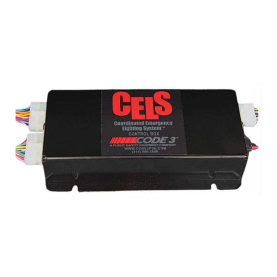
Introduction The CELS™ Coordinated Emergency Lighting System (hereafter called "the system") is designed to be mounted in the interior of the ve- hicle and can control all of the emergency vehicle lighting on your slick top vehicle to flash synchronously with the programmability of a CC lightbar! The system can also dim the entire emergency lighting system. -
Page 3: Installation, Mounting, & Wiring
The CELS Dual Color XT4 & PAR36 Light Heads are "STEADY BURN ONLY" light heads and rely on the CELS Controller for controlling flash pat- terns. The CELS Dual Color XT4 & PAR36 Light Heads have (3) control wires, (2) Power wires and (1) Ground Wire. The power wire colors match the colors of the LEDs in the light heads. - Page 4 • Verify that the Front and Rear CELS Output Harness Plugs are in their correct locations See Figure 2 on page 3 (The plugs are labeled as to their function). If they have been unplugged they can be switched by accident! •...
- Page 5 XT4 LIGHT HEAD WIRE COLOR TABLE PAR36 LIGHT HEAD WIRE COLOR TABLE THE BLACK WIRE IS ALWAYS THE GROUND WIRE THE BLACK WIRE IS ALWAYS THE GROUND WIRE LED COLOR DUAL / SINGLE POWER WIRE COLORS LED COLOR DUAL / SINGLE POWER WIRE COLORS RED / AMBER DUAL...
-
Page 6: Wiring Diagram Package 1
CELS WIRING DIAGRAM - PACKAGE - 1 PAR36 LT HD PAR36 LT HD DRIVER SIDE PASSENGER SIDE TYP SEE PAGE 5 CHART FOR WIRE COLORS DRIVER SUPERVISOR-U SIDE VIEW XT4 MIRROR LIGHT PASSENGER TYP SEE PAGE 5 CHART FOR WIRE COLORS... -
Page 7: Wiring Diagram Package 2
CELS WIRING DIAGRAM - PACKAGE - 2 PAR36 LT HD PAR36 LT HD DRIVER SIDE PASSENGER SIDE TYP SEE PAGE 5 CHART FOR WIRE COLORS PASSENGER ONLY DRIVER SUPERVISOR-U SIDE VIEW XT4 MIRROR LIGHT PASSENGER TYP SEE PAGE 5 CHART... -
Page 8: Wiring Diagram Package 3
CELS WIRING DIAGRAM - PACKAGE - 3 PAR36 LT HD PAR36 LT HD DRIVER SIDE PASSENGER SIDE TYP SEE PAGE 5 CHART FOR WIRE COLORS SUPERVISOR-U DRIVER SIDE VIEW XT4 MIRROR LIGHT PASSENGER TYP SEE PAGE 5 CHART FOR SIDE VIEW... -
Page 9: Wiring Diagram Package 4
CELS WIRING DIAGRAM - PACKAGE - 4 PAR36 LT HD PAR36 LT HD DRIVER SIDE PASSENGER SIDE TYP SEE PAGE 5 CHART FOR WIRE COLORS PASSENGER SIDE DRIVER SIDE VIEW SUPERVISOR-U XT4 MIRROR LIGHT TYP SEE PAGE 5 CHART PASSENGER... -
Page 10: Wiring Diagram Package 5
CELS WIRING DIAGRAM - PACKAGE - 5 PAR36 LT HD PAR36 LT HD DRIVER SIDE PASSENGER SIDE TYP SEE PAGE 5 CHART XT4 LIGHT XT4 LIGHT XT4 LIGHT XT4 LIGHT FOR WIRE COLORS HEAD HEAD HEAD HEAD DRIVER SIDE VIEW... -
Page 11: Wiring Diagram Package 6
CELS WIRING DIAGRAM - PACKAGE - 6 ATTACH BLACK / RED WIRE TO GROUND AFTER PROGRAMMING IS COMPLETE CUSTOMER SUPPLIED WIRE TYP FRONT OUTPUT WIRES NOT USED REAR OUTPUT CONTROL INPUT WIRES WIRES YELLOW 1 YELLOW GRAY 2 GRAY POWER & GROUND... -
Page 12: Functionality-Flash Pattern Selection
3-Level Flashing Feature Flash patterns are based on the 600-series lightbar software (where a single set of the 7 combinations of 3-level inputs configures the entire bar, instead of configuring/flashing in pairs). This feature will flash Supervisor and Citadel heads, as well as XT4 and PAR36 heads (primaries only if secondaries are configured as Takedowns). - Page 13 Rear Cutoff Feature The Rear Cutoff feature uses the RCUT input to cut off the rear (Citadel) flashing (primary) outputs. This feature (by definition of cutoff) overrides the 3-Level functionality to the rear. This function is not programmable. This feature will be unaffected by ArrowStik functionality. Rear Cutoff will not affect Cruise function.
-
Page 14: Notes
Notes:... - Page 15 Notes:...
- Page 16 Notes:...
-
Page 17: Warranty
*Code 3, Inc. reserves the right to repair or replace at its discretion. Code 3, Inc. assumes no responsibility or liability for expenses incurred for the removal and /or reinstallation of products requiring service and/or repair.; nor for the packaging, handling, and shipping: nor for the handling of products returned to sender after the service has been rendered.


Need help?
Do you have a question about the CELS and is the answer not in the manual?
Questions and answers