Xylem LOWARA e-IXPS Installation, Operation And Maintenance Instructions
Hide thumbs
Also See for LOWARA e-IXPS:

Subscribe to Our Youtube Channel
Related Manuals for Xylem LOWARA e-IXPS


Summary of Contents for Xylem LOWARA e-IXPS
- Page 1 Installation, Operation and Maintenance Instructions e-IXPS Pumps according to ISO 2858 and ISO 5199 Applicare qui l’adesivo con il codice a barre Apply the adhesive bar code nameplate here...
-
Page 2: Table Of Contents
en – Original instructions Table of Contents Introduction and Safety ............................5 Introduction ..............................5 Hazard levels and safety symbols ........................5 User safety ................................ 6 Protection of the environment ......................... 7 Spare parts................................ 7 Handling and Storage ............................... 8 Unit inspection upon delivery .......................... - Page 3 en – Original instructions Overload protection ........................... 21 4.5.4 Operation with frequency converter (VSD) ....................21 4.5.5 Use and Operation ..............................22 Precautions ..............................22 Intended use ..............................23 Checking the rotation direction ........................24 Start-up ................................24 Stopping ................................. 25 Maintenance ................................
- Page 4 en – Original instructions WEEE (UK) ..............................39 Declarations ................................ 40 EC Declaration of Conformity (Original) ....................... 40 10.1 UKCA Declaration of Conformity (Original) ....................41 10.2 Warranty ................................43 Information ..............................43 11.1 e-IXPS - Installation, Operation and Maintenance Instructions...
-
Page 5: Introduction And Safety
Special version pumps may be supplied with supplementary instruction manuals. For situations not considered in the manual or in the commercial documentation, contact Xylem or the Authorised Distributor. 1.2 Hazard levels and safety symbols Before using the unit, the user must read, understand and comply with the indications of the danger warnings in order to avoid the following risks: •... -
Page 6: User Safety
en – Original instructions Complementary symbols Symbol Description Electrical hazard Hot surface hazard Danger, pressurized system Ionizing radiation hazard Specific marking for explosion protection Do not use flammable liquids Do not use corrosive liquids Read the instruction manual Ionizing radiation hazard 1.3 User safety Strictly comply with current health and safety regulations. -
Page 7: Protection Of The Environment
Identify the spare parts with the product codes directly on the site www.lowara.com/spark. Contact Xylem or the Authorised Distributor for technical information. e-IXPS - Installation, Operation and Maintenance Instructions... -
Page 8: Handling And Storage
3. Release the unit by removing the screws and/or cutting the straps, if fitted. 4. Check the unit for integrity and to make sure that there are no missing components. 5. In case of damage or missing components, promptly contact Xylem or the Authorised Distributor. -
Page 9: Handling Of The Packed Unit Using A Forklift Truck
en – Original instructions 2.2.1 Handling of the packed unit using a forklift truck The Figure shows the types of packaging and the lifting points. 1. Cardboard box with wooden base 2. Wooden crate 2.2.2 Lifting with a crane WARNING: Use ropes, chains and/or slings (hereinafter referred to as "ropes"), hooks and/or clasps (hereinafter referred to as "hooks"), shackles or eyebolts that comply with the applicable directives and are suitable for use. -
Page 10: Storage
en – Original instructions Preparing the unit for lifting The figure shows how to harness and lift the unit with or without motor. 1. Use the ropes to make a tie harness. 2. Fix the ropes to the crane. 3. Lift the crane and tension the ropes without lifting the unit. Lifting and positioning 1. -
Page 11: Storage Of The Packed Unit
This operation is essential in environments with cold temperatures. Otherwise, any residual liquid in the unit could have an adverse effect on its condition and performance. For more information on long-term storage contact the Xylem sales company or Authorised Distributor. -
Page 12: Description Of The Product
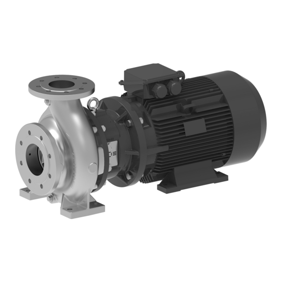
en – Original instructions 3 Description of the Product 3.1 Features The product is a single-stage centrifugal end-suction pump with rigid coupling used with standard electric motors. Intended use • Water supply • Water transfer and circulation • Process cooling and heating •... -
Page 13: Data Plates
en – Original instructions 3.2 Data plates 1. Pump or pump unit type 2. Maximum operating pressure 3. Maximum liquid operating temperature 4. Full impeller diameter (non-trimmed impellers only) 5. Manufacturing date + serial number 6. Product code 7. Weight 8. -
Page 14: Part Names
en – Original instructions 3.4 Part names XIPS_M0002_A_sc 1. Discharge body volute casing 2. Bolt 3. Lifting lug 4. Motor adapter 5. Plug 6. Impeller 7. Wear ring 8. Impeller key 9. Impeller nut 10. Plug 11. Plug 12. O-ring 13. -
Page 15: Installation
en – Original instructions 4 Installation 4.1 General precautions Before starting, make sure that the safety instructions shown in Introduction and Safety on page 5 have been fully read and understood. WARNING: All the hydraulic and electrical connections must be completed by a technician possessing the technical-professional requirements outlined in the current regulations. - Page 16 en – Original instructions Installation XIPS_M0007_A_sc 1. Drill the tie rod holes in accordance with the quantity, diameter and centre distances shown in the technical catalogue. 2. Insert the tie rods into the holes and secure them with chemical anchors. 3.
-
Page 17: Hydraulic Connection
en – Original instructions 4.3 Hydraulic connection 4.3.1 Precautions WARNING: The piping system must be sized to ensure safety at the maximum operating pressure and temperature. WARNING: Danger of hot and/or toxic liquid escaping from non-sealed piping system connections Support the piping system independently to prevent them from weighing on the unit. Secure the piping system to the unit ports making sure to comply with the permitted forces and torques. -
Page 18: Forces And Torques Applicable To The Ports
en – Original instructions 7. To exclude the unit from the system for the purpose of maintenance, install: • An on-off valve on the suction side • An on-off valve on the discharge side, downstream the check valve and pressure gauge, also useful for regulating the flow rate. -
Page 19: Auxiliary Connections
en – Original instructions 125-80-.. 125 2765 2485 2240 4340 1470 1050 1330 2243 80 1575 1435 1750 2757 1120 805 910 1652 125-100-.. 125 2765 2485 2240 4340 1470 1050 1330 2243 100 2100 1890 2345 3672 1225 875 1015 1816 150-125-.. -
Page 20: Guidelines For Electrical Connection
en – Original instructions NOTE: Only use dynamically balanced motors with half-sized key at the shaft end (EN 60034-14), and with normal vibration rate (N). NOTE: Only use three-phase motors with sizes and powers in compliance with local laws / regulations / standards. -
Page 21: Overload Protection
en – Original instructions NOTE: The above table is provided by way of non-exhaustive example. Always refer to the motor manual. 4.5.4 Overload protection 1. Install an appropriate motor protector in the control panel, with D curve in accordance with the current shown on the data plate. -
Page 22: Use And Operation
en – Original instructions 5 Use and Operation 5.1 Precautions Before starting, make sure that the safety instructions shown in Introduction and Safety on page 5 and in General precautions on page 15 have been fully read and understood. WARNING: Start-up and first operation must be done by a technician possessing the technical-professional requirements outlined in the current regulations. -
Page 23: Intended Use
en – Original instructions WARNING: Danger of hot and/or toxic liquid spillage due to the on-off valve being closed It is prohibited to operate the unit with the on-off valves on the suction and discharge sides closed. If the unit needs to operate for more than a few seconds with the discharge valve closed, or below the minimum flow rate, install a bypass circuit. -
Page 24: Checking The Rotation Direction
en – Original instructions 5.3 Checking the rotation direction Preparing the unit WARNING: Temperature increase due to contact between rotating and fixed components Checking the direction of rotation by running the unit dry is strictly forbidden. 1. Check that all the operations described in the previous paragraphs have been completed correctly. -
Page 25: Stopping
en – Original instructions Start up 1. Shut off the discharge on-off valve almost completely. 2. Fully open the suction on-off valve. 3. Start the unit. 4. Gradually open the discharge on-off valve and adjust it until the duty point is reached, as soon as the motor reaches full speed 5. -
Page 26: Maintenance
en – Original instructions 6 Maintenance 6.1 Precautions Before starting, make sure that the safety instructions shown in Introduction and Safety on page 5 have been fully read and understood. WARNING: Maintenance must be done by a technician possessing the technical-professional requirements outlined in the current regulations. -
Page 27: Periodic Maintenance
en – Original instructions WARNING: Make sure that the drained liquid cannot cause damage or injuries. WARNING: It is prohibited to dispose of lubricating fluids and other hazardous substances in the environment. 6.2 Periodic maintenance DANGER: Excessive temperatures due to friction Regularly check the coupling protection and other covers of rotating parts for deformation and enough clearance from the rotating parts themselves. -
Page 28: Long Periods Of Inactivity
If the unit has not been used for more than 2 years, replace the grease in the bearings. 6.4 Spare parts ordering Identify the spare parts with the product codes directly on the site www.lowara.com/spark. Contact Xylem or the Authorised Distributor for further technical information. 6.5 Tightening torques Block pump with bolted casing cover... - Page 29 en – Original instructions 920.01 M12x1,5 50 (440) Torque wrench M16x1,5 80 (710) M20x1,5 120 (1060) M24x2,0 170 (1500) 922.02 M16X1.5 80 (710) Torque wrench M20X1.5 100 (900) M24X2 130 (1150) M30X2 180 (1600) M36X2 220 (1950) e-IXPS - Installation, Operation and Maintenance Instructions...
-
Page 30: Troubleshooting
Maintenance must be done by a technician possessing the technical-professional requirements outlined in the current regulations. WARNING: If a fault cannot be corrected or is not mentioned, contact Xylem or the Authorised Distributor. 7.2 The unit does not start Cause... -
Page 31: The Thermal Overload Protection Triggers Or The Fuses Trip
Bring the flow rate back within the permitted limits Liquid too thick Check the liquid Room temperature too high Decrease the temperature Unit faulty Contact Xylem or the Authorised Distributor 7.7 The motor becomes excessively hot Cause Solution Room temperature too high Decrease the temperature... -
Page 32: When Switched Off, The Unit Turns In The Opposite Direction
Solution Damaged seal due to: Replace the seal and check it to identify the cause of the • wear damage. Contact Xylem or the Authorised Distributor • thermal shock • chemical incompatibility • other 7.13 The frequency converter is in error mode or turned off... -
Page 33: Technical Information
< 50% at 40°C (104°F), unless otherwise indicated in the instructions of the pump and the electric motor. NOTE: If the humidity exceeds the stated limits, contact Xylem or the Authorised Distributor. Elevation < 1000 m (3280 ft) above sea level. -
Page 34: Electrical Specifications
en – Original instructions EN 1092 NN, UU RR, TT, RN [(25 bar (363 psi) only] ASME B16.5 NN, UU RR, TT, RN [(25 bar (363 psi) only] 8.4 Electrical specifications See the motor data plate. Permitted tolerances for the supply voltage Frequency Hz Phase ~ No. -
Page 35: Maximum Number Of Starts Per Hour
en – Original instructions 8.5 Maximum number of starts per hour Power, kW Starts / h 0.75 – 3 4 – 7.5 11 – 22 30 – 37 45 – 75 NOTE: The above table is provided by way of non-exhaustive example. Always refer to the motor manual. -
Page 36: Section Drawings And List Of Components
en – Original instructions Model Diameter of Shaft Mechanical ports, diameter, seal, mm (in) mm (in) mm (in) 100-65-315 100 (4) 65 (2 1/2) 42 (1.65) 53 (2.09) 125-80-160, 125-80-200, 125-80-250 125 (5) 80 (3) 32 (1.26) 43 (1.69) 125-80-315, 125-80-400 125 (5) 80 (3) 42 (1.65) -
Page 37: List Of Components
en – Original instructions S0 with bolted casing cover Unbalanced single mechanical seal, bolted casing cover and 1 piece motor adapter. 8.8.2 List of components Code Description 102.01 Volute casing 161.01 Casing cover 210.10 Stub Shaft 230.01 Impeller 341.01 Motor adapter 341.02 Motor size adapter 400.01... - Page 38 en – Original instructions 502.02 Wear ring 504.01 Spacer ring 554.01 Washer 554.02 Washer 554.09 Washer 554.13 Washer 561.01 681.01 Safety guard 800.00 Motor 900.01 Lifting lug 901.12 Hexagon head screw 901.13 Hexagon head screw 901.14 Hexagon head screw 902.01 Stud 902.02 Stud...
-
Page 39: Disposal
en – Original instructions 9 Disposal 9.1 Precautions WARNING: The unit must be disposed of through approved companies specialised in the identification of different types of materials (steel, copper, plastic, etc.). WARNING: It is prohibited to dispose of lubricating fluids and other hazardous substances in the environment. -
Page 40: Declarations
Refer to the specific marking declaration found on the product. 10.1 EC Declaration of Conformity (Original) Xylem Service Italia S.r.l., with headquarters in Via Vittorio Lombardi 14 - 36075 Montecchio Maggiore VI - Italy, hereby declares that the product Electric pump unit (see the label on the “Safety and Other Information” manual) fulfils the relevant provisions of the following European Directives •... -
Page 41: Ukca Declaration Of Conformity (Original)
S.I. 2008/1597 - Supply of Machinery (Safety) Regulations 2008 and subsequent amendments (Schedule 2 - Part 2 - ANNEX II – natural or legal person authorised to compile the technical file: Xylem Service Austria GmbH – Ernst Vogel-Strasse 2 - 2000 Stockerau - Austria). - Page 42 2012/3032 - The Restriction of the Use of Certain Hazardous Substances in Electrical and Electronic Equipment Regulations 2012 and subsequent amendments) Lowara is a trademark of Xylem Inc. or one of its subsidiaries. e-IXPS - Installation, Operation and Maintenance Instructions...
-
Page 43: Warranty
en – Original instructions 11 Warranty 11.1 Information For information on the warranty refer to the commercial documentation. e-IXPS - Installation, Operation and Maintenance Instructions... - Page 44 For more information on how Xylem can help you, go to www.xylem.com Xylem Service Italia S.r.l. Via Vittorio Lombardi 14 36075 –...
Need help?
Do you have a question about the LOWARA e-IXPS and is the answer not in the manual?
Questions and answers