Table of Contents
Advertisement
Quick Links
Advertisement
Table of Contents

Related Manuals for Xylem Lowara e-IXP


Summary of Contents for Xylem Lowara e-IXP
- Page 1 Additional Installation, Operation and Maintenance Manual e-IXP(A), e-IXPC(A), e-IXPF(A) Pumps according to ISO 2858 and ISO 5199 ATEX II 2G Ex h IIC T5…T3 Gb Applicare qui l’adesivo con il codice a barre Apply the adhesive bar code nameplate here...
-
Page 2: Table Of Contents
en – Original instructions Table of Contents Introduction and Safety ............................5 Introduction ..............................5 Hazard levels and safety symbols ........................5 User safety ................................ 6 Explosion protection ............................6 Explosion protection marking ........................7 1.4.1 Temperature limits ............................7 1.4.2 Operation of the pump .......................... - Page 3 en – Original instructions Precautions ..............................21 4.3.1 Guidelines for the hydraulic system ......................22 4.3.2 Forces and torques applied to the ports ....................22 4.3.3 Auxiliary Connections ..........................24 4.3.4 Alignment of the motor-pump coupling ....................... 24 Disassembling the coupling guards ......................25 4.4.1 Checking the coupling alignment ......................
- Page 4 en – Original instructions When switched off, the unit turns in the opposite direction ................ 44 The unit starts and stops too frequently ......................44 7.10 The unit does not stop ........................... 44 7.11 The unit is leaking at the mechanical seal ..................... 44 7.12 The frequency converter is in error mode or turned off ................
-
Page 5: Introduction And Safety
Special version pumps may be supplied with supplementary instruction manuals. For situations not considered in the manual or in the commercial documentation, contact Xylem or the Authorised Distributor. 1.2 Hazard levels and safety symbols Before using the unit, the user must read, understand and comply with the indications of the danger warnings in order to avoid the following risks: •... -
Page 6: User Safety
en – Original instructions Complementary symbols Symbol Description Electrical hazard Hot surface hazard Danger, pressurized system Specific marking for explosion protection Danger, explosive atmosphere Danger, risk of explosion Do not use flammable liquids Do not use corrosive liquids Read the instruction manual 1.3 User safety Strictly comply with current health and safety regulations. -
Page 7: Explosion Protection Marking
en – Original instructions DANGER: Potentially explosive atmosphere hazard Observe the explosion protection warnings in this manual when installing, operating and maintaining the unit in potentially explosive atmospheres. DANGER: Potentially explosive atmosphere hazard All the electric material used for the connection must: •... -
Page 8: Operation Of The Pump
°C (°F) temperature liquid, °C (°F) °C (°F) 100 (212) 85 (185), contact -20 …+40 • Call Xylem or the authorised distributer Xylem or the (-4 … +104) • Allowed for these models: Authorised ≤ 1800 min − Distributor... -
Page 9: Electric Switches And Control Devices, Instrumentation And Accessories
en – Original instructions Operation: 1. Start up the pump with the suction side fully open and and the discharge side valve fully open: start-up with closed non-return valve is however also possible. 2. Immediately after the start-up, adjust the discharge side valve to the operating point, refer to section 5.3. -
Page 10: Protection Of The Environment
Identify the spare parts with the product codes directly on the site www.lowara.com/spark. Contact Xylem or the Authorised Distributor for technical information. e-IXP(A), e-IXPC(A), e-IXPF(A) – Additional Installation, Operation and Maintenance Manual... -
Page 11: Handling And Storage
3. Release the unit by removing the screws and/or cutting the straps, if fitted. 4. Check the unit for integrity and to make sure that there are no missing components. 5. In case of damage or missing components, promptly contact Xylem or the Authorised Distributor. -
Page 12: Handling Of The Packed Unit Using A Forklift Truck
en – Original instructions 2.2.1 Handling of the packed unit using a forklift truck The Figure shows the types of packaging and the lifting points. 1. Cardboard box with wooden base 2. Wooden crate 2.2.2 Lifting with a crane WARNING: Use ropes, chains and/or slings (hereinafter referred to as "ropes"), hooks and/or clasps (hereinafter referred to as "hooks"), shackles or eyebolts that comply with the applicable directives and are suitable for use. - Page 13 en – Original instructions 2. Fix the ropes to the crane. 3. Lift the crane and tension the ropes without lifting the unit. Lifting and positioning 1. Lift and move the unit slowly 2. Set the unit down slowly. 3. Depending on the model: •...
-
Page 14: Storage
This operation is essential in environments with cold temperatures. Otherwise, any residual liquid in the unit could have an adverse effect on its condition and performance. For more information on long-term storage contact the Xylem sales company or Authorised Distributor. -
Page 15: Description Of The Product
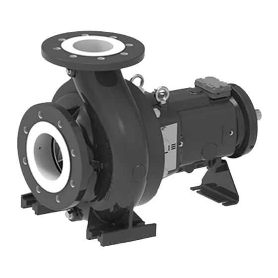
en – Original instructions 3 Description of the product 3.1 Features The product is a single-stage end suction pump in back pull-out configuration with bearing support, compliant with EN 22858 and ISO 2858 standards. The product can be supplied as an electric pump (pump with electric motor), or as a pump only. -
Page 16: Data Plate
en – Original instructions 3.2 Data plate 1. Pump or electric pump type 2. Maximum operating pressure 3. Maximum liquid operating temperature 4. Full impeller diameter (non-trimmed impellers only) 5. Manufacturing date + serial number 6. Product code 7. Weight 8. -
Page 17: Atex Label
en – Original instructions 3.4 ATEX label The illustration shows the pump label. The motor and the coupling must have their own label. 1. Specific Marking for Explosion Protection 2. Group 3. Category 4. Atmosphere (G= combustible gases, vapours or mists) 5. - Page 18 en – Original instructions 1. Volute casing 2. Bolt 3. Lifting lug 4. Shaft seal ring 5. Bearing support 6. Shaft seal ring 7. Shaft 8. Coupling key 9. Bearing cover 10. Support foot 11. Plug 12. Impeller 13. Wear ring 14.
-
Page 19: Installation
en – Original instructions 4 Installation 4.1 General precautions Before starting, make sure that the safety instructions shown in Introduction and Safety on page 5 have been fully read and understood. WARNING: Risk of explosion Comply with the local explosion protection regulations. WARNING: Risk of explosion The improper installation of the unit in potentially explosive atmospheres can cause explosion. -
Page 20: Installation On Concrete Foundation
en – Original instructions 4.2.3 Installation on concrete foundation Foundation requirements • The concrete must have a compression resistance of C12/15 and meet the requirements of exposure class XC1 according to EN 206-1 • Sizes must be appropriate for the sizes of the unit support plate •... -
Page 21: Frame Installation
en – Original instructions DANGER: Explosion due to static charge Ensure that the base plate is earthed correctly. Reducing vibrations The motor and the flow of liquid in the piping can generate vibrations, which may be amplified from the possible incorrect installation of the unit and the piping. See Hydraulic connection on page 21. -
Page 22: Guidelines For The Hydraulic System
en – Original instructions 4.3.2 Guidelines for the hydraulic system 1. Support the piping system independently to prevent them from weighing on the unit. 2. Remove any welding residues, deposits and impurities from the piping system in order to avoid damage to the unit: the method and duration of the cleaning operation must be adapted to the materials of the unit and the gaskets. - Page 23 en – Original instructions Material code NN (UU) Suction port Discharge port Model Forces N Torques Nm Forces N Torques Nm ΣF ΣM ΣF ΣM 40-25- 50-32- 65-50- 1146 65-40- 1146 80-65- 1379 1146 100-65- 1379 100-80- 100 1173 1050 945 1836 1379 100-65-...
-
Page 24: Auxiliary Connections
en – Original instructions 4.3.4 Auxiliary Connections NOTE: Unused or incorrectly used connections may cause malfunction and damage to the unit. 1. Suction port 2. Discharge port 3. Greasing unit M8 nipple 4. Greasing unit M8 nipple 5. G 1/2” drain 6. -
Page 25: Disassembling The Coupling Guards
en – Original instructions 4.4.1 Disassembling the coupling guards XIP_M0010_A_sc 1. Top fastener 2. Top coupling protection 3. Bottom fastener 4. Side fasteners 5. Bottom coupling protection 6. Adjustment ring 1. Unscrew the side fasteners. 2. Unscrew the top fastener. 3. -
Page 26: Installing The Coupling Guards
en – Original instructions NOTE: The radial and axial deviations between the half couplings must not exceed the values indicated by the manufacturer. Refer to the motor-pump coupling instruction manuals for more information. The figure shows the correct alignment of the coupling. XIP_M0011_A_sc 4.4.3 Installing the coupling guards XIP_M0012_A_sc... -
Page 27: Mechanical Seals And Auxiliary Systems
en – Original instructions 4.6 Mechanical seals and auxiliary systems DANGER: Explosion due to overheating of the packing seals To prevent overheating, observe the instructions for seals P2 and P3 found in the table 1. Find the type of seal by reading the third and second last letters of the identification code. 2. -
Page 28: Electrical Connection
en – Original instructions NOTE: If there is no leak, stop the unit immediately and replace the seal. 8. Reinstall the guards. 4.7 Electrical connection 4.7.1 Precautions Electrical measures DANGER: Potentially explosive atmosphere hazard For the electrical connections, make sure to comply with the requirements of the IEC 60079-14 standard. -
Page 29: Guidelines For Electrical Connection
en – Original instructions 4.7.2 Guidelines for electrical connection 1. Check that the electrical leads are protected against: • High temperature • Vibrations • Collisions • Liquids. 2. Check that the power supply line is provided with: • A short circuit protection device of appropriate size •... -
Page 30: Operation With Frequency Converter
en – Original instructions 4.7.5 Operation with frequency converter WARNING: If a variable speed application is required, refer to the instructions and catalogues of the motor and frequency converter manufacturers. DANGER: Potentially explosive atmosphere hazard Check if the frequency converter is suitable to operate in potentially explosive atmospheres. DANGER: Potentially explosive atmosphere hazard Check if the electric motor is suitable to operate in potentially explosive atmospheres when connected to the frequency converter. -
Page 31: Use And Operation
en – Original instructions 5 Use and operation 5.1 Precautions Before starting, make sure that the safety instructions shown in Introduction and Safety on page 5 and in Installation on page 19 have been fully read and understood. WARNING: Start-up and first operation must be done by a technician possessing the technical-professional requirements outlined in the current regulations. -
Page 32: Checking The Rotation Direction
en – Original instructions WARNING: Physical injury hazard If applicable, check that the protection devices of the coupling are installed. WARNING: Electrical hazard Check that the unit is properly connected to the mains power supply. WARNING: Hot surface hazard Be aware of the extreme heat generated by the unit. WARNING: It is prohibited to place flammable materials near the unit. -
Page 33: Start-Up
en – Original instructions • Disconnect the power supply • Invert two of the three wires of the power supply cord. 6. Check the direction of rotation again. 5.3 Start-up DANGER: Explosion hazard due to excessive temperature Do not keep the on-off valve on the discharge side in the closed position in order to throttle the pump for more than a few seconds. -
Page 34: Maintenance
en – Original instructions 6 Maintenance 6.1 Precautions Before starting, make sure that the safety instructions shown in Introduction and Safety on page 5 have been fully read and understood. CAUTION: Maintenance must be done by a technician possessing the technical-professional requirements outlined in the current regulations. -
Page 35: Periodic Maintenance
en – Original instructions WARNING: Make sure that the drained liquid cannot cause damage or injuries. WARNING: It is prohibited to dispose of lubricating fluids and other hazardous substances in the environment. 6.2 Periodic maintenance DANGER: Excessive temperatures due to friction Regularly check the coupling protection and other covers of rotating parts for deformation and enough clearance from the rotating parts themselves. - Page 36 en – Original instructions Check the operation of the device in standby Every 2 weeks Check If the unit is subjected to chemical or abrasive wear, check its Every 6 months condition Check the terminal board for any signs of overheating and Every year arc flashes Cleaning...
-
Page 37: Grease Top Up
en – Original instructions 6.2.1 Grease top up XIP_M0016_A_sc 1. Greasing nipple 2. Greasing nipple 3. Thrust bearing 4. Radial bearing Use NLGI n. 2 lithium bearing grease or similar. 1. Clean the nipples. 2. Insert the greasing unit in the first nipple and refill. 3. -
Page 38: Changing The Oil
• Pour point: -15°C (5°F) • Operating temperature: higher than the permissible bearing temperature. NOTE: If the ambient temperature is below -10°C (14°F), use specific oil: contact Xylem or its Authorised Distributor. 1. Remove the drain plug (4). 2. Drain all the oil from the unit or, if the unit is new, any residual liquid. -
Page 39: Replacement Of The Shaft Seal
If the unit has not been used for more than 2 years, replace the grease in the bearings. 6.4 Spare parts ordering Identify the spare parts with the product codes directly on the site www.lowara.com/spark. Contact Xylem or the Authorised Distributor for further technical information. e-IXP(A), e-IXPC(A), e-IXPF(A) – Additional Installation, Operation and Maintenance Manual... -
Page 40: Tightening Torques
en – Original instructions 6.5 Tightening torques D - D XIP_M0019_A_sc e-IXP(A), e-IXPC(A), e-IXPF(A) – Additional Installation, Operation and Maintenance Manual... - Page 41 en – Original instructions Position number Bolt size Tightening torque Nm Tool (lbf·in) A, B 55 (490) Torque wrench 100 (890) 210 (1850) 350 (3100) M12X1.5 50 (440) M16X1.5 80 (710) M20X1.5 120 (1060) M24X2 170 (1500) M30X2 280 (2500) 15 (130) Standard wrench 30 (270)
-
Page 42: Troubleshooting
Maintenance must be done by a technician possessing the technical-professional requirements outlined in the current regulations. WARNING: If a fault cannot be corrected or is not mentioned, contact Xylem or the Authorised Distributor. 7.2 The unit does not start Cause... -
Page 43: The Thermal Overload Protection Triggers Or The Fuses Trip
Bring the flow rate back within the permitted limits Liquid too thick Check the liquid Room temperature too high Decrease the temperature Unit faulty Contact Xylem or its Authorised Distributor 7.7 The motor becomes excessively hot Cause Solution Room temperature too high Decrease the temperature... -
Page 44: When Switched Off, The Unit Turns In The Opposite Direction
Solution Damaged seal due to: Replace the seal and check it to identify the cause of the • wear damage. Contact Xylem or its Authorised Distributor • thermal shock • chemical incompatibility • other 7.13 The frequency converter is in error mode or turned off... -
Page 45: Technical Information
Relative air humidity < 50% at 40°C (104°F). NOTE: If the humidity exceeds the stated limits, contact Xylem or the Authorised Distributor. Elevation < 1000 m (3280 ft) above sea level. CAUTION: Danger of motor overheating If the unit is exposed to temperatures or installed at an altitude greater than those stated, reduce the power output of the motor according to the coefficients reported in the table. -
Page 46: Maximum Operating Pressure
en – Original instructions 8.3 Maximum operating pressure The chart shows the pumped liquid pressure and temperature limits permitted for the materials of the unit, depending on the type of flange. EN 1092 NN, UU RR, TT, RN [(25 bar (363 psi) only] ASME B16.5 NN, UU RR, TT, RN [(25 bar (363 psi) only]... -
Page 47: Maximum Number Of Starts Per Hour
en – Original instructions 8.5 Maximum number of starts per hour Power, kW Starts / h 0.75 - 3 4 - 7.5 11 - 22 30 - 37 45 - 75 90 - 160 200 - 315 355 - 500 NOTE: The above table is provided by way of non-exhaustive example. -
Page 48: Construction And Maintenance Data
en – Original instructions 8.7 Construction and maintenance data Model Diameter of ports, Shaft Mechanical seal, Type of bearing Quantity of grease, Quantity of mm (in) diameter, mm (in) pump side/motor side, oil, L (US qt mm (in) g (oz) dry) Suction Discharge... -
Page 49: Section Drawings And List Of Components
en – Original instructions 8.8 Section drawings and list of components 8.8.1 Drawings To find the drawing corresponding to your model, identify the type of mechanical seal and lubrication of the bearing support: see paragraph Identification code on page 16. S1G with clamped casing cover Unbalanced single mechanical seal with clamped casing cover and grease lubricated medium duty bearing bracket... - Page 50 en – Original instructions S1G with bolted casing cover Unbalanced single mechanical seal with bolted casing cover and grease lubricated medium duty bearing bracket e-IXP(A), e-IXPC(A), e-IXPF(A) – Additional Installation, Operation and Maintenance Manual...
- Page 51 en – Original instructions Unbalanced single mechanical seal with clamped casing cover and oil lubricated medium duty bearing bracket e-IXP(A), e-IXPC(A), e-IXPF(A) – Additional Installation, Operation and Maintenance Manual...
- Page 52 en – Original instructions Shaft sealing packing with internal flush, shaft sleeve and grease lubricated medium duty bearing bracket and radial lip seal ring e-IXP(A), e-IXPC(A), e-IXPF(A) – Additional Installation, Operation and Maintenance Manual...
- Page 53 en – Original instructions CSG, CDG, CQG Cartridge mechanical seal (single or double) with clamped casing cover and oil lubricated medium duty bearing bracket e-IXP(A), e-IXPC(A), e-IXPF(A) – Additional Installation, Operation and Maintenance Manual...
- Page 54 en – Original instructions IXPI With inducer on extended shaft, shaft sealing packing with shaft sleeve and grease lubricated medium duty bearing bracket and radial lip seal ring. e-IXP(A), e-IXPC(A), e-IXPF(A) – Additional Installation, Operation and Maintenance Manual...
-
Page 55: List Of Components
en – Original instructions 8.8.2 List of components Code Description 102.01 Volute casing 161.01 - 161.05 Cover 183.01 Foot 210.01 Shaft 230.01 Impeller 321.01 Ball bearing 321.02 Angular contact ball bearing 330.01 Bearing support 330.02 Bearing support 360.01 Bearing cover 360.02 Bearing cover 400.01... - Page 56 en – Original instructions 904.10 Set screw 914.01 - 914.03 Set screw 920.01 - 920.04 Hexagon nut 920.09 Hexagon nut 922.01 Impeller nut 923.01 Bearing nut - self-locking 932.01 Retaining ring 940.01, 940.02 Code for additional inducer parts Description Suction nozzle Inducer 412.13 O-ring...
-
Page 57: Disposal
en – Original instructions 9 Disposal 9.1 Precautions WARNING: The unit must be disposed of through approved companies specialised in the identification of different types of materials (steel, copper, plastic, etc.). WARNING: It is prohibited to dispose of lubricating fluids and other hazardous substances in the environment. -
Page 58: Declarations
− EN 809: 2012 − EN ISO 12100:2010 − EN ISO 14120:2015 − EN 60204-1:2019 A modification on the pump set which is not approved by Xylem Inc. invalidate this declaration. Montecchio Maggiore, 17/02/2022 Marco Ferretti Chairman of the Board of Directors rev.00... - Page 59 Signed for and on behalf of: Xylem Service Italia S.r.l Montecchio Maggiore, 17/02/2022 Marco Ferretti Chairman of the Board of Directors rev.00 Lowara is a trademark of Xylem Inc. or one of its subsidiaries. e-IXP(A), e-IXPC(A), e-IXPF(A) – Additional Installation, Operation and Maintenance Manual...
-
Page 60: Pump
EN 809: 2012 − EN ISO 12100:2010 − EN ISO 14120:2015 A modification on the pump which is not approved by Xylem Inc. invalidates this declaration. Montecchio Maggiore, 17/02/2022 Marco Ferretti (Operation Director & Site Leader) rev.00 EU Declaration of Conformity (n. 67) 1. - Page 61 Signed for and on behalf of: Xylem Service Italia S.r.l Montecchio Maggiore, 17/02/2022 Marco Ferretti Chairman of the Board of Directors rev.00 Lowara is a trademark of Xylem Inc. or one of its subsidiaries. e-IXP(A), e-IXPC(A), e-IXPF(A) – Additional Installation, Operation and Maintenance Manual...
-
Page 62: Warranty
en – Original instructions 11 Warranty 11.1 Information For information on the warranty refer to the commercial documentation. e-IXP(A), e-IXPC(A), e-IXPF(A) – Additional Installation, Operation and Maintenance Manual... - Page 63 en – Original instructions e-IXP(A), e-IXPC(A), e-IXPF(A) – Additional Installation, Operation and Maintenance Manual...
- Page 64 For more information on how Xylem can help you, go to www.xylem.com Xylem Service Italia S.r.l. Via Vittorio Lombardi 14 36075 –...
Need help?
Do you have a question about the Lowara e-IXP and is the answer not in the manual?
Questions and answers