
Related Manuals for Xylem LOWARA e-SHE Series


Summary of Contents for Xylem LOWARA e-SHE Series
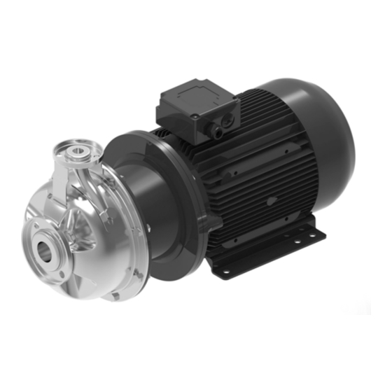
- Page 1 Additional Installation, Operation and Maintenance Instructions e-SHE, e-SHS Series Horizontal Centrifugal Pump Units in AISI 316 Stainless Steel...
-
Page 2: Table Of Contents
en – Original Instructions Table of Contents Introduction and Safety ............................5 Introduction ..............................5 Safety ................................5 1.2.1 Danger levels and safety symbols ....................... 5 1.2.2 User safety ..............................6 1.2.3 Protection of the environment ........................7 1.2.4 Sites exposed to ionizing radiations......................7 Handling and Storage ............................... - Page 3 en – Original Instructions Use and operation ..............................26 Precautions ..............................26 Filling - Priming .............................. 27 5.2.1 Positive suction head installation ......................27 5.2.2 Suction lift installation ..........................27 Rotation sense check (three-phase motors) ....................28 5.3.1 Wrong rotation direction ........................... 28 Start-up ................................
- Page 4 en – Original Instructions WEEE 2012/19/EU (50 Hz) ..........................44 Declarations ................................ 45 Warranty ................................47 11.1 Information ..............................47 e-SHE, e-SHS – Additional Installation, Operation and Maintenance Instructions...
-
Page 5: Introduction And Safety
The instructions and warnings of this manual apply to the standard unit as described in the sale documentation. Special version pumps may be supplied with supplementary instruction manuals. For situations not considered in the manual or in the sales document, contact Xylem or the Authorised Distributor. -
Page 6: User Safety
en – Original Instructions Complementary symbols Symbol Description Electrical hazard Hot surface hazard Danger, system pressurized Do not use flammable liquids Do not use corrosive liquids Read the instruction manual 1.2.2 User safety Strictly comply with current health and safety regulations. WARNING: This unit must be used only by qualified users. -
Page 7: Protection Of The Environment
en – Original Instructions 1.2.3 Protection of the environment Disposal of packaging and product Comply with the current regulations on sorted waste disposal. Leaking of fluid If the unit contains lubricating fluid, take appropriate measures to prevent the dispersion of leaks into the environment. -
Page 8: Handling And Storage
en – Original Instructions 2 Handling and Storage 2.1 Handling of the packed unit WARNING: Crushing hazard (limbs) The unit and its components may be heavy: risk of crushing. WARNING: Always wear personal protective equipment. WARNING: Check the gross weight marked on the packaging. WARNING: Handle the unit in compliance with the current regulations on "manual load handling", to avoid undesirable ergonomic conditions causing risks of back-spine injury. -
Page 9: Unit Inspection Upon Delivery
In both cases, promptly contact Xylem or the Authorised Distributor from whom the product was purchased. Unpacking and inspection of the unit CAUTION: Cut and abrasion hazard Always wear personal protective equipment. - Page 10 en – Original Instructions The unit must be harnessed and lifted as shown in figures 1 and 2. Figure 1: Lifting a unit with foot on the pump Figure 2: Lifting a unit with foot on the motor e-SHE, e-SHS – Additional Installation, Operation and Maintenance Instructions...
-
Page 11: Storage
ESH_M0006_A_sc 2. Follow the same instructions for the storage of the packed unit. For more information on long-term storage contact the Xylem sales company or Authorised Distributor. – Additional Installation, Operation and Maintenance Instructions... -
Page 12: Technical Description
en – Original Instructions 3 Technical Description 3.1 Designation Horizontal centrifugal pump unit with end suction and radial discharge ports, in AISI 316 stainless steel. 3.2 Denomination of the models Model Description ESHE Close-coupled construction with an impeller keyed directly to the motor shaft extension ESHS Construction with a rigid coupling keyed to the standardised motor shaft extension 3.3 Data plate... -
Page 13: Identification Code
en – Original Instructions 3.4 Identification code E S H E 1 6 0 5 V S N A 1 11 1 12 1. Model denomination: ESHE or ESHS 2. Close-coupled [E] or rigid [S] coupling, or bare shaft [ ] 3. -
Page 14: Intended Use
en – Original Instructions e-SHS Counterwear ring Impeller key Impeller locking nut Wear ring Pump body Impeller Seal housing Drain plug Mechanical seal 10. Rigid coupling 11. Elastomers 12. Motor adapter 13. Motor 3.6 Intended use • Water supply and water treatment •... -
Page 15: Improper Use
en – Original Instructions 3.7 Improper use WARNING: The unit was designed and built for the use described in the Intended Use section. Any other uses are prohibited, as they could compromise the safety of the user and the efficiency of the unit itself. -
Page 16: Special Applications
– Original Instructions 3.9 Special applications Contact Xylem or the Authorised Distributor in the following cases: • If liquids with a density and/or viscosity value exceeding that of water (such as water and glycol mixture) must be pumped • If the pumped liquid is chemically treated (for example softened, deionized, demineralized etc.) -
Page 17: Installation
en – Original Instructions 4 Installation 4.1 Precautions Before starting, make sure that the safety instructions shown in Introduction and Safety on page 5 have been fully read and understood. DANGER: All the hydraulic and electrical connections must be completed by a technician possessing the technical-professional requirements outlined in the current regulations. -
Page 18: Mechanical Installation
en – Original Instructions 4.2 Mechanical installation Install the unit on a concrete or metal foundation base sufficiently strong to ensure permanent and rigid support. 4.2.1 Installation area 1. Follow the provisions in Operating environment on page 37. 2. Place the unit in a raised position in relation to the floor. 3. -
Page 19: Fastening Of The Unit
en – Original Instructions 4.2.4 Fastening of the unit Phase Action Illustration If present, remove the plugs covering the suction and discharge ports. Place the unit on the foundation. Align the suction and discharge ports to their piping. Unit with foot on the pump: secure with 3 bolts with resistance class 8.8 or higher. -
Page 20: Hydraulic Connection
en – Original Instructions 4.3 Hydraulic connection DANGER: All the hydraulic and electrical connections must be completed by a technician possessing the technical-professional requirements outlined in the current regulations. WARNING: Piping must be sized to ensure safety at the maximum operating pressure. WARNING: Install appropriate seals between the unit couplings and the pipings. - Page 21 en – Original Instructions EHM_M0017_B_sc Figure 4: Suction lift installation Pump unit Anti-vibration joint Overpressure safety on-off valve On-off valve Pressure gauge Check valve Electrode probes or float Automatic relief valve Foot check valve with filter 10. Electric panel 11. Filling on-off valve. General guidelines 1.
-
Page 22: Electrical Connection
en – Original Instructions 4. In case of suction lift installation, the piping must have an increasing slope towards the unit exceeding 2%; to avoid air pockets. Also install: • A vacuum pressure gauge • A foot check valve that guarantees full opening (full section) •... -
Page 23: Guidelines For Electrical Connection
en – Original Instructions 4.4.2 Guidelines for electrical connection 1. Check that the electrical leads are protected against: • High temperature • Vibrations • Collisions. 2. Check that the power supply line is provided with: • A short circuit protection device of appropriate size •... - Page 24 en – Original Instructions NOTICE: Only use single-phase or three-phase motors with sizes and powers in compliance with European standards. NOTICE: The mains voltage and frequency must match the specifications on the data plate. Electrical connection of the motor 1. Open the terminal box cover. 2.
-
Page 25: Operation With Frequency Converter
en – Original Instructions 4.4.5 Operation with frequency converter The three-phase motors can be connected to a frequency converter for speed control. • The converter exposes the insulation of the motor to a greater load, determined by the length of the connecting cable: observe the requirements of the Manufacturer of the frequency converter •... -
Page 26: Use And Operation
en – Original Instructions 5 Use and operation 5.1 Precautions WARNING: Injuries hazard Check that the protection devices of the coupling are installed, when applicable: risk of physical injury. WARNING: Make sure that the drained liquid cannot cause damage or injuries. WARNING: Electrical hazard Check that the unit is properly connected to the mains power supply. -
Page 27: Filling - Priming
en – Original Instructions 5.2 Filling - Priming WARNING: In the case of liquids that are excessively hot or cold, pay attention to the risk of injury. The figure shows the unit connected to the discharge and suction pipes. On-off valve, discharge side On-off valve, suction side Filling plug. -
Page 28: Rotation Sense Check (Three-Phase Motors)
en – Original Instructions 5.3 Rotation sense check (three-phase motors) Before starting the unit: NOTICE: Check that the shaft can turn smoothly. The figure shows the motor fan cover. 1. Locate the arrow on the fan cover, the adapter or the coupling, to determine the correct direction of rotation of the motor. -
Page 29: Stopping
en – Original Instructions 1. Check that all the operations described in the previous paragraphs have been completed correctly. 2. Shut off the discharge on-off valve almost completely. 3. Fully open the suction on-off valve. 4. Start the unit. 5. Gradually open the discharge on-off valve until half open. 6. -
Page 30: Maintenance
en – Original Instructions 6 Maintenance 6.1 Precautions Before starting, make sure that the instructions shown in Introduction and Safety on page 5 have been fully read and understood. WARNING: Maintenance must be done by a technician possessing the technical-professional requirements outlined in the current regulations. -
Page 31: Tightening Torques
en – Original Instructions 6.2 Tightening torques The figure shows the threaded fittings of the unit. ESH_M0020_A_sc Position Size Torque, Nm (lbf·in) number 45 (400) ± 15% 110 (970) ± 15% 200 (1770) ± 15% G3/8 40 (350) ± 25% 40 (350) ±... -
Page 32: Maintenance Schedule
5. Before restarting the unit, check that the shaft is rotating freely, without mechanical impediments. 6.5 Spare parts ordering Identify the spare parts with the product codes directly on the site www.lowara.com/spark. Contact Xylem or the Authorised Distributor for technical information. e-SHE, e-SHS – Additional Installation, Operation and Maintenance Instructions... -
Page 33: Troubleshooting
WARNING: Observe the safety instructions given in Use and operation and Maintenance. WARNING: If a fault cannot be corrected or is not mentioned, contact Xylem or the Authorised Distributor. 7.2 The unit does not start Cause Solution... -
Page 34: The Thermal Overload Protection Triggers
en – Original Instructions 7.5 The thermal overload protection triggers The motor thermal overload protection triggers occasionally, or after the unit has been running for a few minutes. Cause Solution It is calibrated at a value too low in relation to the rated current of Recalibrate the motor Input voltage outside the rated limits... -
Page 35: The Unit Produces Excessive Noise And/Or Vibrations
• replace the expansion vessel with another suitable one, or • undersized, or • install an expansion vessel • not installed Oversized unit Contact Xylem or the Authorised Distributor 7.11 The unit never stops (automatic start/stop) Cause Solution The required flow rate is greater than the one expected... -
Page 36: The Unit Is Leaking
en – Original Instructions 7.12 The unit is leaking Cause Solution Worn mechanical seal Replace the mechanical seal, or Fit a mechanical seal with harder seal faces Mechanical seal damaged due to thermal shock (presence of air Replace the mechanical seal bubbles in the unit) Defective mechanical seal Replace the mechanical seal... -
Page 37: Technical Information
Otherwise, replace the motor with a more powerful one. Relative air humidity < 50% at 40°C (104°F). NOTICE: If the humidity exceeds the stated limits, contact Xylem or the Authorised Distributor. Elevation < 1000 m (3300 ft) above sea level. NOTICE: Danger of motor overheating If the unit is exposed to temperatures higher than those indicated, reduce the motor power;... -
Page 38: Downgrading The Motor
en – Original Instructions 8.1.1 Downgrading the motor The following diagram shows the downgrading coefficients K according to the ambient temperature; ET is the maximum ambient temperature indicated on the data plate. 0,95 0,85 0,75 0,65 0,55 °C The following diagram shows the downgrading coefficients K according to altitude. -
Page 39: Liquid Temperature And Maximum Operating Pressure
Maximum input pressure 1 max Maximum pressure generated by the unit Maximum operating pressure NOTE: The formula applies to units with motor with axially locked bearing on the drive side (standard Xylem). – Additional Installation, Operation and Maintenance Instructions e-SHE, e-SHS... -
Page 40: Maximum Head
en – Original Instructions 8.3 Maximum head The tables show the maximum pressure head H according to the model. 50 Hz @2900 min motors Model P, kW Model P, kW 25-125 0.75 50-125 17.5 25-125 50-125 20.6 25-160 50-125 24.8 25-160 50-160 33.8... - Page 41 en – Original Instructions P4 25-250 16.4 P4 50-250 P4 25-250 20.4 P4 50-250 P4 32-125 A 0.25 P4 65-160 0.55 P4 32-125 0.25 P4 65-160 0.75 P4 32-160 A 0.25 P4 65-160 A P4 32-160 0.25 P4 65-160 P4 32-200 0.37 P4 65-160 P4 32-200...
-
Page 42: Maximum Number Of Starts Per Hour
en – Original Instructions 40-160 80-200 40-160 80-200 40-200 80-200 40-200 80-250 40-250 80-250 40-250 80-250 60 Hz @1750 min motors Model P, kW Model P, kW P4 25-125 0.25 P4 50-125 0.37 P4 25-160 0.25 P4 50-125 0.55 P4 25-160 0.37 P4 50-160 0.75... -
Page 43: Protection Class
en – Original Instructions NOTICE: If a motor other than the one supplied with the pump unit is used, check the maximum number of starts shown in the motor manual. 8.5 Protection class IP 55. 8.6 Electrical specifications See the motor data plate. Permitted tolerances for the supply voltage Frequency Hz Phase ~... -
Page 44: Disposal
Producer of EEE as per Directive 2012/19/EU: (IE) Xylem Water Solutions Ireland Ltd - 50 Broomhill Close - Airton Road - D24 Tallaght - Dublin 24 (MT) (GB) Xylem Water Solutions UK Ltd - Millwey Rise Industrial Estate – Axminster - Devon EX13 5HU Classification according to product type, use and current local laws e-SHE, e-SHS –... -
Page 45: Declarations
10 Declarations EC Declaration of Conformity (Original) Xylem Service Italia S.r.l., with headquarters in Via Vittorio Lombardi 14 - 36075 Montecchio Maggiore VI - Italy, hereby declares that the product Pump unit (see the label on the Safety and Other Information manual) fulfils the relevant provisions of the following European Directives: •... - Page 46 Signed for and on behalf of: Xylem Service Italia S.r.l. Montecchio Maggiore, 12/09/2019 Amedeo Valente (Director of Engineering and R&D) rev.00 Lowara is a trademark of Xylem Inc. or one of its subsidiaries. e-SHE, e-SHS – Additional Installation, Operation and Maintenance Instructions...
-
Page 47: Warranty
en – Original Instructions 11 Warranty 11.1 Information For information on the warranty refer to the documentation of the sale contract. – Additional Installation, Operation and Maintenance Instructions e-SHE, e-SHS... - Page 48 For more information on how Xylem can help you, go to www.xyleminc.com Xylem Service Italia S.r.l. Via Vittorio Lombardi 14 36075 –...
Need help?
Do you have a question about the LOWARA e-SHE Series and is the answer not in the manual?
Questions and answers