Xylem LOWARA e-SV Series Installation, Operation And Maintenance Manual
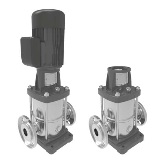
Multistage vertical pump unit
Hide thumbs
Also See for LOWARA e-SV Series:

Related Manuals for Xylem LOWARA e-SV Series


Summary of Contents for Xylem LOWARA e-SV Series
- Page 1 Installation, Operation and Maintenance Manual e-SV Series Multistage Vertical Pump Unit...
-
Page 2: Table Of Contents
en - Original instructions Table of Contents Introduction and Safety ............................. 5 Introduction ............................... 5 Safety ................................5 1.2.1 Danger levels and safety symbols ......................... 5 1.2.2 User safety ..............................6 1.2.3 Protection of the environment ........................6 1.2.4 Sites exposed to ionizing radiations ......................6 Handling and Storage .............................. - Page 3 en - Original instructions Precautions ..............................26 Filling - Priming ............................... 27 5.2.1 Positive suction head installation ....................... 27 5.2.2 Suction lift installation ..........................27 Checking the direction of rotation (three-phase motors) ................28 5.3.1 Wrong rotation direction ..........................28 Start-up ................................
- Page 4 en - Original instructions 10.2 EU Conformity Declaration (n. EMCD08)......................43 10.3 Pump EC Declaration of Conformity (Original) ....................44 Warranty ................................45 11.1 Information ..............................45 e-SV series - Installation, Operation and Maintenance Manual...
-
Page 5: Introduction And Safety
The instructions and warnings of this manual apply to the standard unit as described in the sale documentation. Special version pumps may be supplied with supplementary instruction manuals. For situations not considered in the manual or in the sales document, contact Xylem or the Authorised Distributor. -
Page 6: User Safety
en - Original instructions Complementary symbols Symbol Description Electrical hazard Magnetic hazard Hot surface hazard 1.2.2 User safety Strictly comply with current health and safety regulations. WARNING: This unit must be used only by qualified users. Qualified users are people able to recognise the risks and avoid hazards during installation, use and maintenance of the unit. -
Page 7: Handling And Storage
en - Original instructions 2 Handling and Storage 2.1 Handling of the packed unit WARNING: Crushing hazard (limbs) The unit and its components may be heavy: risk of crushing. WARNING: Always wear personal protective equipment. WARNING: Check the gross weight marked on the packaging. WARNING: Handle the unit in compliance with the current regulations on "manual load handling", to avoid undesirable ergonomic conditions causing risks of back-spine injury. -
Page 8: Unit Handling
- Original instructions In both cases, promptly contact Xylem or the Authorised Distributor from whom the product was purchased. Unpacking and inspection of the unit CAUTION: Cut and abrasion hazard Always wear personal protective equipment. 1. Remove packing materials from the product. -
Page 9: Storage
en - Original instructions WARNING: Lift and handle the unit slowly to avoid stability issues. WARNING: During handling, make sure to avoid injury to people and animals, and/or damage to property. WARNING: Do not use eyebolts screwed on the motor for handling the unit. The eyebolts screwed on the motor must only be used to move the unit upright from its horizontal position on the ground, and only for as long as strictly necessary. - Page 10 Figure 4: Drain plug For further information about preparation for long-term storage, please contact Xylem or the Authorised Distributor. e-SV series - Installation, Operation and Maintenance Manual...
-
Page 11: Technical Description
en - Original instructions 3 Technical Description 3.1 Designation Multistage vertical centrifugal pump unit, non-self-priming. The product may be supplied as full pump unit (pump and motor), or as pump only. 3.2 Data plate The data plate is a label showing: ... - Page 12 en - Original instructions 2 2 S V 1 0 F L 1 1 0 1 10 1 11 EHM_M0005_A_sc Figure 6: Identification code for models 1, 3, 5, 10, 15, 22SV Position Description Notes number Rated flow rate 22 = m Series name Motor operation Empty = standard...
- Page 13 en - Original instructions 5 S V 2 A G L 5 1 11 EHM_M0006_A_sc Figure 7: Identification code for models 33, 46, 66, 92, 125SV Position Description Notes number Rated flow rate 125 = m Series name Motor operation Empty = standard H = with Hydrovar®...
-
Page 14: Names Of The Main Components
en - Original instructions 3.3 Names of the main components 1 12 1 18 1 16 1 14 1 17 1 11 1 10 1 15 1 11 1 16 1 14 ESV_M0007_A_ds Figure 8: Main components Position Position Description Description number number... -
Page 15: Improper Use
en - Original instructions 3.5 Improper use WARNING: The unit was designed and built for the use described in the Intended Use section. Any other uses are prohibited, as they could compromise the safety of the user and the efficiency of the unit itself. -
Page 16: Special Applications
- Original instructions 3.7 Special applications Contact Xylem or the Authorised Distributor in the following cases: If liquids with a density and/or viscosity value exceeding that of water (such as water and glycol mixture) must be pumped If the pumped liquid is chemically treated (for example softened, deionized, demineralized etc.) -
Page 17: Installation
en - Original instructions 4 Installation 4.1 Precautions Make sure you have read and understood the safety instructions in the Introduction and Safety chapter before starting work. DANGER: Potentially explosive atmosphere hazard It is prohibited to start the unit in environments with potentially explosive atmospheres or with combustible dusts WARNING: Always wear personal protective equipment. -
Page 18: Permitted Positions
en - Original instructions If the space available is any less, refer to the technical catalogue. 4.2.2 Permitted positions Figure 9: Unit position 4.2.3 Installation on concrete foundation Requirements The concrete must have a compression resistance of C12/15 and meet the requirements of exposure class XC1 according to EN 206-1 ... -
Page 19: Reducing Vibrations
en - Original instructions Table 1: Sizes of the anchoring bolts Model L1, mm L2, mm L3, mm L4, mm Ø, mm Bolt size 1, 3, 5SV 10,15, 22SV 130 33SV 46, 66, 92SV 190 125SV 1. If present, remove the plugs covering the suction and discharge ports. 2. - Page 20 en - Original instructions Figure 12: Suction lift installation diagram Position Position Description Description number number Pump unit Electrode probes or float Anti-vibration joint Automatic relief valve Overpressure safety on-off valve Foot check valve with filter On-off valve Electric panel Pressure gauge Pressurised circuit Minimum pressure switch...
-
Page 21: Flange Forces And Torques
en - Original instructions 8. Install a pressure gauge (or a vacuum pressure gauge, in case of suction lift installation) on the suction side, and a pressure gauge on the discharge side, for checking the actual operating pressure of the pump unit. 9. -
Page 22: Electrical Connection
en - Original instructions 4.4 Electrical connection DANGER: All the hydraulic and electrical connections must be completed by a technician possessing the technical-professional requirements outlined in the current regulations. DANGER: Electrical hazard Before starting work, check that the unit is unplugged and that the pump unit, the control panel and the auxiliary control circuit cannot restart, even unintentionally. -
Page 23: Guidelines For The Control Electric Panel
en - Original instructions 4.4.3 Guidelines for the control electric panel NOTICE: The electric panel must match the ratings on the unit data plate. Improper combinations could damage the motor. 1. Install appropriate devices for protecting the motor from overloads and short circuits: Motor Safety features ... - Page 24 en - Original instructions Positioning of the motor terminal box The position of the terminal box may be changed to facilitate the electric connections: 1. Remove the 4 bolts that secure the motor to the pump. 2. Rotate the motor in the desired position without removing the couplings. 3.
-
Page 25: Operation With Frequency Converter
en - Original instructions Motor without automatic reset thermal overload protection 1. If the motor is used with full load, then set the value to the nominal current value on the data plate of the pump unit. 2. If the motor is used with partial load, then set the value of the operating current measured with a current pincer. -
Page 26: Use And Operation
en - Original instructions 5 Use and operation 5.1 Precautions WARNING: Injuries hazard Check that the protection devices of the coupling are installed, when applicable: risk of physical injury. WARNING: Make sure that the drained liquid cannot cause damage or injuries. WARNING: Electrical hazard Check that the unit is properly connected to the mains power supply. -
Page 27: Filling - Priming
en - Original instructions 5.2 Filling - Priming WARNING: In the case of liquids that are excessively hot or cold, pay attention to the risk of injury. NOTICE: The unit must be filled and vented properly before it can be started. 5.2.1 Positive suction head installation See the figure below. -
Page 28: Checking The Direction Of Rotation (Three-Phase Motors)
en - Original instructions 6. Close the plug (D). 7. Slowly fully open the on-off valve on the discharge side. Models 10, 15, 22, 33, 46, 66, 92 and 125SV 1. Open the on-off valves on the suction (A) and discharge (B) sides. 2. -
Page 29: Start-Up
en - Original instructions 2. Invert two of the three wires of the power cable in the terminal box of the motor or in the control electric panel. 3. Connect the power supply. 4. Start the pump unit. 5. Check the direction of rotation through the coupling protection, or through the motor cover. -
Page 30: Stopping
en - Original instructions Settling of the mechanical seal The pumped liquid lubricates the seal faces of the mechanical seal; under normal conditions, a small amount of liquid may leak out. When the unit is run for the first time, or immediately after the seal is replaced, more liquid may temporarily leak out. -
Page 31: Maintenance
en - Original instructions 6 Maintenance 6.1 Precautions Before starting work, make sure that the instructions in the Introduction and Safety sections have been fully read and understood. WARNING: Maintenance must be done by a technician possessing the technical-professional requirements outlined in the current regulations. -
Page 32: Tightening Torques Of The Threaded Connections
35 (310) 30 (265) 40 (354) 40 (354) 35 (310) 15 (133) 6.5 Ordering spare parts Identify the spare parts with the product codes directly on the site www.lowara.com/spark. Contact Xylem or the Authorised Distributor for technical information. e-SV series - Installation, Operation and Maintenance Manual... -
Page 33: Troubleshooting
WARNING: Observe the safety requirements in the chapters on Use and Operation and Maintenance. WARNING: If a fault cannot be corrected or is not mentioned, contact Xylem or the Authorised Distributor. 7.2 The unit does not start Cause Remedy... -
Page 34: The Thermal Overload Protection Triggers Or The Fuses Trip
en - Original instructions 7.4 The thermal overload protection triggers or the fuses trip The motor thermal overload protection triggers or the fuses trip when the unit starts. Cause Remedy It is calibrated at a value too low in relation to Recalibrate the rated current of the motor Missing power supply phase... -
Page 35: When Switched Off, The Unit Turns In The Opposite Direction
undersized, or suitable one, or not installed install an expansion vessel Oversized unit Contact Xylem or the Authorised Distributor 7.10 The unit never stops (automatic start/stop) Cause Remedy The required flow rate is greater than the one... - Page 36 en - Original instructions e-SV series - Installation, Operation and Maintenance Manual...
-
Page 37: The Unit Is Leaking
en - Original instructions 7.11 The unit is leaking Cause Remedy Worn mechanical seal Replace the mechanical seal or fit a mechanical seal with harder seal faces Mechanical seal damaged due to thermal shock Replace the mechanical seal (presence of air bubbles in the unit) Defective mechanical seal Replace the mechanical seal Mechanical seal damaged due to temperature... -
Page 38: Technical Information
0 to 40°C (32 to 104°F). Relative air humidity < 50% at 40°C (104°F). NOTICE: If the temperature and humidity exceed the stated limits, contact Xylem or the Authorised Distributor. Elevation < 1000 m (3280 ft) above sea level. NOTICE: If the unit is installed at an altitude greater than the stated one, reduce the power output of the motor according to the coefficients below, or replace it with a more powerful one. -
Page 39: Maximum Operating Pressure
[°F] Figure 19: Temperature-pressure diagram P1max + Pmax ≤ Maximum operating pressure (PN) NOTE: The formula applies to units with motor with axially locked bearing on the drive side (standard Xylem). P1max P1max + Pmax Pmax Figure 20: Pressure diagram 8.4 Maximum number of starts per hour... -
Page 40: Protection Class
3 + 1 220/380 ± 5 380/660 ± 10 8.8 Noise level Measured in free field at a distance of one metre from the unit, with standard Xylem motor operating without load. 50 Hz motors Table 6: LpA noise level, db (A) -
Page 41: Materials In Contact With The Liquid
en - Original instructions 8.9 Materials in contact with the liquid Model Materials 1, 3, 5, 10, 15, 22 Stainless steel 33, 46, 66, 92, 125 Stainless steel, cast iron 8.10 Mechanical seal Model Motor power, kW Rated diameter, mm Balance Rotatio Version... -
Page 42: Disposal
en - Original instructions 9 Disposal 9.1 Precautions WARNING: The unit must be disposed of through approved companies specialised in the identification of different types of materials (steel, copper, plastic, etc.). WARNING: It is prohibited to dispose of lubricating fluids and other hazardous substances in the environment. -
Page 43: Declarations
10 Declarations 10.1 Pump unit EC Declaration of Conformity (Original) Xylem Service Italia S.r.l., with headquarters in Via Vittorio Lombardi 14 - 36075 Montecchio Maggiore VI - Italy, hereby declares that the product pump unit (see label on SAFETY manual) fulfils the relevant provisions of the following European Directives: ... -
Page 44: Pump Ec Declaration Of Conformity (Original)
- Original instructions 10.3 Pump EC Declaration of Conformity (Original) Xylem Service Italia S.r.l., with headquarters in Via Vittorio Lombardi 14 - 36075 Montecchio Maggiore VI - Italy, hereby declares that the product pump (see label on SAFETY manual) fulfils the relevant provisions of the following European Directives: ... -
Page 45: Warranty
en - Original instructions 11 Warranty 11.1 Information For information on the warranty refer to the documentation of the sale contract. e-SV series - Installation, Operation and Maintenance Manual... - Page 46 en - Original instructions e-SV series - Installation, Operation and Maintenance Manual...
- Page 47 en - Original instructions e-SV series - Installation, Operation and Maintenance Manual...
- Page 48 Our products and services move, treat, analyze, monitor and return water to the environment, in public utility, industrial, residential and commercial building services settings. Xylem also provides a leading portfolio of smart metering, network technologies and advanced analytics solutions for water, electric and gas utilities. In...
Need help?
Do you have a question about the LOWARA e-SV Series and is the answer not in the manual?
Questions and answers