
Subscribe to Our Youtube Channel
Related Manuals for Renesas YMCRPR8C25


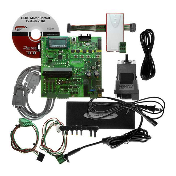
Summary of Contents for Renesas YMCRPR8C25
- Page 1 User Powerful Processors – Easy to Use™ R8C/Tiny BLDC Motor Control Evaluation Kit (YMCRPR8C25) User’s Manual Rev. 1.1 March 2008 www.renesas.com...
-
Page 2: Table Of Contents
5.2.1. HALL Sensor Based BLDC Demo .................... 12 5.2.2. BEMF (Sensor-less) BLDC Demo..................... 12 5.3. Sample Code ........................... 12 5.4. Windows GUI YMCRPR8C25 Control Program - LEM ..............12 5.4.1. OVERVIEW ..........................12 5.4.2. Running Motor........................... 13 5.4.3. Plotting Data..........................13 6.0 System Details............................ - Page 3 D.1 Serial Communications ........................21 D.1.1 Setting the COM Port Number....................21 D.1.2 USB COM Ports......................... 21 D.1.3 LEM Serial Errors ........................21 D.2 LEM Hangs ............................21 YMCRPR8C25 User’s Manual Rev 1.1 3/ 21 March 2008...
-
Page 4: Limited Guarantee And Support
Limited Guarantee and Support Renesas Technology America, Inc. warrants the YMCRPR8C25 kit to be free from component or assembly defects for a period of 90 days from the date of purchase. Settlement is limited to repair or replacement of the product only. Renesas Technology America, Inc. does not assume any liability arising out of the application or use of any product, circuit or procedure described herein. -
Page 5: Introduction
1.0 Introduction The YMCRPR8C25 kit is a low-cost Evaluation Kit for evaluating the R8C/25 MCU for use in 3 phase BLDC motor applications. Renesas firmware is included for evaluating motor drive capabilities of the R8C family of processors. The kit comes with a complete software development tool chain for Renesas MCUs, including the High- performance Embedded Workshop (HEW), which includes an Integrated Development Environment (IDE), Graphical User Interface (GUI), the M16C C-compiler, assembler and linker. -
Page 6: Cd-Rom
3.1. Host Computer Requirements The minimum requirement to be able to use the software that comes with the YMCRPR8C25 kit is a PC with a serial port and Microsoft Windows 2000, or XP. For debugging with the optional (user supplied) E8a in-chip debugging emulator, the PC also needs a USB port. -
Page 7: Hew (High-Performance Embedded Workshop)
UART, or with external flash chips. 3.4.5. Renesas AutoUpdate Included with HEW 4.0 and later is the Renesas AutoUpdate utility. This utility can be configured to search our website automatically for updates of the Renesas tools installed on your PC. See the HEW User’s Manual on how to use this feature. -
Page 8: Software Build Process Overview
“YMCRPR8C25” project generator. 3.4.7. Software Build Process Overview The YMCRPR8C25 kit allows the user to write or modify the provided code to evaluate the R8C/25 Motor Control solution. Code can be compiled and downloaded to the MCU. Debugging can be accomplished with E8a On-chip debugging Emulator. -
Page 9: Hardware
4.0 Hardware 4.1. YMCRPR8C25 System Overview Figure 4-1 shows the YMCRPR8C25 Hardware with major components identified. Isolated Serial Connector Line cord 2x8 LCD Module Isolated E8a Motor LEDs (4 places) Debugger Connector 24 VDC Power Supply Motor Motor Winding Connection... -
Page 10: Ymcrpr8C25 System Block Diagram
4.3.1. YMCRPR8C25 Board The YMCRPR8C25 includes the R8C/25 and support circuitry. Note that to operate the motor the jumpers must be set correctly for the method selected: sensor (Hall) or sensor-less (Back-EMF). The board is shipped with the jumpers in the Hall Sensor mode. -
Page 11: Jumper Settings
The R8C/25 group of 16-bit single-chip Flash microcontrollers (MCU) is part of the R8C/Tiny Family. The hardware and software manuals for the R8C/25 group of microcontrollers can be found from the Start menu Start > (All) Programs > Renesas > High-performance Embedded Workshop > Manual Navigator after software installation. -
Page 12: Motor Control Demo And Support Software
The plots can include such things as speed, current, IPM temperature, etc… While you have HEW open and connected to the YMCRPR8C25 board through the E8a, launch the GUI by simply browsing to C:\Workspace\YMCRPR8C25\Utilites and double click on MCRP GUI icon (lem.exe). -
Page 13: Running Motor
400uS per data value plotted. So if you are plotting four items (variables), you are sampling at 400uS * 4, or 1600uS (1.6mS) update rate. This data may also be captured in a CSV file for plotting or analyzing under Excel. YMCRPR8C25 User’s Manual Rev 1.1 13/ 21 March 2008... -
Page 14: System Details
10A, IGBT based Power Module 6.2. Power Supply Requirements The YMCRPR8C25 Board requires a supply voltage of 24.0V DC, and will draw approximately 0.5 amps when running the included motor with no load. Running the motor under load will require more current. -
Page 15: Operating Environment
6.3. Operating Environment The table below lists the environmental conditions for using and storing the YMCRPR8C25 board. Store the board in a conductive bag inside the original factory packaging. Table 6-3: Operating and Storage Environments Environmental Condition Ambient Temperature Ambient Humidity Operating 0 to 55°C... -
Page 16: Appendix A. Reference Documents
Data Sheet for DMB0224B10002 24VDC BLDC Motor HEW Target Server Sample code Various samples of HEW Target Applications for the NOTE: These documents are contained in the Utilities Folder on the YMCRPR8C25 Install CD. YMCRPR8C25 User’s Manual Rev 1.1 16/ 21 March 2008... -
Page 17: Appendix B. Hardware Notes
B.1 Over-Current Circuit The YMCRPR8C25 makes current measurements on the low side of the IPM though a 0.05 ohm, non- inductive resistor. This shunt voltage is fed into the gain stage (node SU in figure B-1). The gain is set at 2.2. -
Page 18: Back-Emf Detect Circuit
B.2 Back-EMF Detect Circuit The YMCRPR8C25 uses filters, divider resistors and comparators to detect the Back-EMF in hardware. Figure B-2 shows the Filter/Divider combination. To Motor Outputs Figure B-2: Back-EMF divider and filters The outputs are then fed to comparators to detect the correct threshold for “zero-cross” in the motor. One typical circuit is shown in Figure B-3. -
Page 19: Appendix C. Pcb Component Layout
Appendix C. PCB Component Layout C.1 Component Placement - Top Figure C.1: Component Placement – Top YMCRPR8C25 User’s Manual Rev 1.1 19/ 21 March 2008... -
Page 20: Component Placement - Bottom
C.2 Component Placement - Bottom Figure C.2: Component Placement - Bottom YMCRPR8C25 User’s Manual Rev 1.1 20/ 21 March 2008... -
Page 21: Appendix D. Troubleshooting
D.1 Serial Communications The YMCRPR8C25 board requires the E8a debugger and an operational COM port in order to run the board from the LEM GUI. The COM port can be an problem on some computers that do not have a hardware COM port, or which do not have it on COM1.
Need help?
Do you have a question about the YMCRPR8C25 and is the answer not in the manual?
Questions and answers