Megger MIT400/2 User Manual
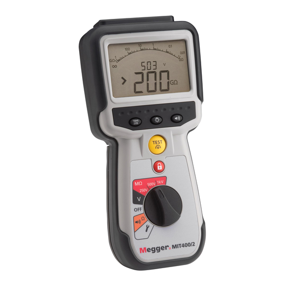
Mit400/2 series
insulation and continuity testers
Hide thumbs
Also See for MIT400/2:
- Manual (24 pages) ,
- Quick start manual (8 pages) ,
- User manual (47 pages)
Table of Contents
Advertisement
Advertisement
Table of Contents


Need help?
Do you have a question about the MIT400/2 and is the answer not in the manual?
Questions and answers