
Related Manuals for Stryker POWER PRO TL


Summary of Contents for Stryker POWER PRO TL
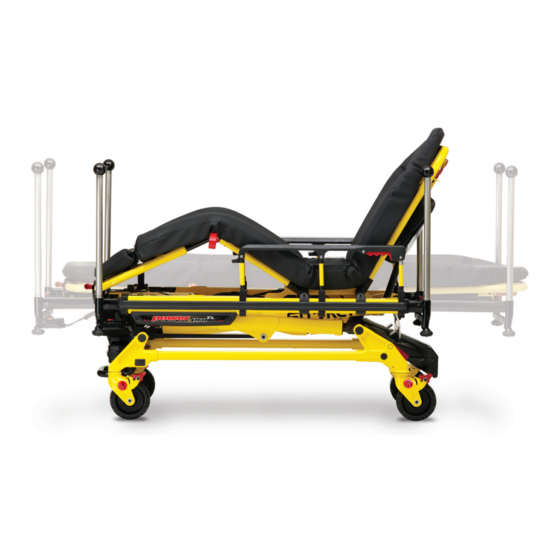
- Page 1 POWER PRO TL Ambulance Cot Model 6550 RUGGED® Operations/Maintenance Manual For Parts or Technical Assistance: USA: 1-800-327-0770 (option 2) Canada: 1-888-233-6888 2007/06 6550-009-001 REV B www.stryker.com...
-
Page 3: Table Of Contents
Stryker EMS Return Policy ........ - Page 4 3-Stage I.V. Assembly, Patient Right - 6550-215-000 ..........114 6550-009-001 REV B www.stryker.com...
- Page 5 POWER PRO TL ........
-
Page 6: Introduction
Height measured from bottom of mattress at seat section to ground level. Cot is weighed with 1 battery and without mattress and restraints. Stryker reserves the right to change specifications without notice. The POWER PRO TL is designed to be compatible with competitive cot fastener systems. WALT ®... -
Page 7: Warning / Caution / Note Definition
This provides special information to make maintenance easier or important instructions clearer. www.stryker.com 6550-009-001 REV B... - Page 8 Stryker UK Limited Hambridge Rd. Newbury, Berkshire RG14 5EG, England Please have the serial number of your Stryker product available when calling Stryker Customer Service or Technical Support. include the serial number in all written communication. Serial number HEAD END figure 1 - Cot Serial number &...
-
Page 9: Symbols And Definitions
Medical Equipment Classified by Underwriters Laboratories Inc. with Respect to Electric Shock, Fire, Mechanical and Other Specified Hazards Only in Accordance with UL 60601−1, First Edition (2003) and CAN/CSA C22.2 No. 601.1−M90 with updates 1 and 2. BS EN 1789:2000 Certified. www.stryker.com 6550-009-001 REV B... -
Page 10: Warranty
Stryker’s obligation under this warranty is expressly limited to supplying replacement parts for, or replacing, at its option, any product which is, in the sole discretion of Stryker, found to be defective. Expendable components, i.e. mattresses, restraints, IV poles, storage nets, storage pouches, O2 straps, and other soft goods, have a one (1) year limited warranty with this option. -
Page 11: Stryker Ems Return Policy
Claim will be limited in amount to the actual replacement cost. In the event that this information is not received by Stryker within the fifteen (15) day period following the delivery of the merchandise, or the damage was not noted on the delivery receipt at the time of receipt, the customer will be responsible for payment of the original invoice in full. -
Page 12: Summary Of Safety Precautions
Modifying the product can cause unpredictable operation resulting in injury to the patient or operator. Modifying the product will also void its warranty. • It is the responsibility of the cot operator to ensure the ambulance cot being used in the Stryker cot fastener system meets the installation specifications listed on page 20. - Page 13 SOME CLEANING PRODUCTS ARE CORROSIVE IN NATURE AND MAY CAUSE DAMAGE TO THE PRODUCT IF USED IMPROPERLY. If the products described above are used to clean Stryker patient care equipment, measures must be taken to insure the cots are wiped with clean water and thoroughly dried following cleaning. Failure to properly rinse and dry the cots will leave a corrosive residue on the surface of the cots, possibly causing premature corrosion of critical components.
- Page 14 POWER PRO TL ambulance cot should not be used adjacent to or stacked with other equipment. If adjacent or stacked use is necessary, the model 6550 POWER PRO TL ambulance cot should be observed to verify normal operation in the configuration in which it will be used.
- Page 15 Summary of Safety Precautions WARNING: Pinch Point between litter interface and base when lowering litter. WARNING: Pinch Point figure 2 - Potential Pinch Points www.stryker.com 6550-009-001 REV B...
-
Page 16: Component Identification
Adjustment Handle Backrest Push Bars Gatch/Leg (Optional) Rest Siderail Release Retractable Head Section Retractable Foot Section Lifting Bar Head Section Hydraulic Unit Release Height Adjustment Switch Steer Lock Battery Wheel Lock Casters figure 3 - Cot Components 6550-009-001 REV B www.stryker.com... -
Page 17: Product Inspection
Verify siderails operate and latch properly. Verify backrest cylinder operates properly through range of motion. Verify the leg rest operates properly. Install body restraints. Restraints intact and operating properly. 22-23 No rips or tears in mattress cover. www.stryker.com 6550-009-001 REV B... - Page 18 25-26 Verify equipment hook (if equipped) is installed properly. Verify pocketed backrest storage pouch (if equipped) is installed properly. Verify 36" restraint extender (if equipped) is included. Verify the Bariatric transfer flat (if equipped) is included. 6550-009-001 REV B www.stryker.com...
-
Page 19: Setup Procedures
• Stryker continually seeks advancements in product design and quality. Therefore, while this manual contains the most current product information available at the time of printing, there may be minor discrepancies between your ambulance cot and this manual. -
Page 20: Cot Fastener Installation
Cot fastener installation POWER PRO TL Cot Fastener system, model 6385, 6386, and 6387 are designed to be compatible only with cots which conform to the Cot Fastener Installation specifications listed on the following page. POWER PRO TL Cot Fastener system, model 6385, 6386 and 6387 are not designed for any purpose other than to restrict movement of an ambulance cot being transported in the patient compartment of an ambulance under normal conditions. - Page 21 Cot fastener installation www.stryker.com 6550-009-001 REV B...
-
Page 22: Cot Features
The arrows indicate alternate attachment areas. When attaching the restraint straps to the cot, remember the attachment points should provide both strong anchorage and proper restraint position while not interfering with equipment and accessories. 6550-009-001 REV B www.stryker.com... - Page 23 Inspection of the restraints should be done at least once a month (more frequently if used heavily). Inspection should include checking for a bent or broken receiver or latch plate, torn or frayed webbing, etc. Any restraint showing wear or not operating properly must be replaced immediately. www.stryker.com 6550-009-001 REV B...
-
Page 24: Using The Patient Restraint Belt Extension (Optional Equipment)
Cot features USinG ThE PATiEnT RESTRAinT BELT EXTEnSiOn (OPTiOnAL EqUiPMEnT) Use the restraint belt extension (Stryker part number 6082-160-050) for extra length when buckling the lap belt around large patients. figure 20 - Attaching the Restraint Belt Extension 6550-009-001 REV B... -
Page 25: Pedi-Mate™ Infant Restraint System (Optional Equipment) Attachment Instructions
(see Figure 22). figure 22 - fastening the Pedi-Mate™ Buckle WARninG To avoid accidental release of the Pedi-Mate™, and possible injury to the infant, ensure the buckle is located away from obstructions on the cot or accessories. www.stryker.com 6550-009-001 REV B... - Page 26 These are general instructions for installation of the Pedi-Mate™. Safe and proper use of the Pedi-Mate™ is solely at the discretion of the user. Stryker recommends all users be trained on the proper use of the Pedi-Mate™ before using it in an actual situation.
-
Page 27: Operating The Wheel Lock(S)
25 - Wheel Lock The Power Pro TL includes corner to corner wheel locks as a standard feature with an option to specify locks for all four wheels. To secure the wheel lock(s), press down on the base of the locking pedal (A) until it rests firmly against the surface of the wheel. -
Page 28: Adjusting The Wheel Locking Force
Remove the sleeve (B). Rotate the sleeve counterclockwise to increase the pedal locking force and clockwise to decrease the locking force. Insert the sleeve into the pedal. Reinstall the socket screw. Test the pedal locking force and verify the pedal holds properly before returning the cot to service. 6550-009-001 REV B www.stryker.com... -
Page 29: Adjusting The Footrest And Knee Gatch
To lower the knee Gatch, lift either of the red lifting loops (B) to relieve pressure on the locking mechanism and while holding the loop, push on the red release handle (C) until the bracket disengages. Lower the knee gatch to the flat position. www.stryker.com 6550-009-001 REV B... -
Page 30: Operating The Backrest
Siderails are not intended to serve as a patient restraint device. Refer to pages 22 for proper restraint strap usage. Failure to utilize the siderails properly could result in patient injury. figure 29 - Backrest Elevated and Siderails Raised 6550-009-001 REV B www.stryker.com... -
Page 31: Proper Battery Management: Dwalt Battery Management And Charger Care
Like any piece of rescue equipment, proper care and maintenance will provide the rescuer the best tools to perform the task at hand. Contact Stryker Technical Support with any additional questions at 1-800-784-4336. Operation Range Optimum Operation Range –28°C... -
Page 32: Proper Battery Management: Dwalt Battery Frequently Asked Questions
NiCd cells. Old batteries should be disposed of at a D WALT Service Center. For more information call 1-800-8-BATTERY OR ® 1-800-8-228-8379. WALT ® is a registered trademark of Black & Decker Inc. 6550-009-001 REV B www.stryker.com... -
Page 33: Battery Power Indicator
Only use the battery and charger as specified. • The POWER PRO TL ambulance cot is not for use with an AC adapter. • When charging batteries in an ambulance vehicle, locate the charger either in the forward cab or an enclosed compartment (i.e. -
Page 34: Hour Usage Meter
56. CAUTiOn • A preventative maintenance program should be established for all Stryker EMS equipment. Preventative maintenance may need to be performed more frequently based on the usage level of the product. • Close attention should be given to safety features including, but not limited to:... -
Page 35: Installing The Backrest Storage Pouch (Optional Equipment)
The weight of the equipment in the pocketed backrest storage pouch (if equipped) must not exceed 1.4 stones (20 pounds), (9 kg). • Make sure the pouch does not interfere with the operation of the retractable head section. www.stryker.com 6550-009-001 REV B... -
Page 36: Using The Equipment Hook (Optional Equipment)
The equipment hook is used to hang additional accessories or equipment such as defibrillators or monitors. CAUTiOn To avoid damage to the equipment hook, the weight of the accessories or equipment must not exceed 1.4 stones (20 pounds), (9 kg). 6550-009-001 REV B www.stryker.com... -
Page 37: Operating The Rigid Push Bars And Storage Pouch (Optional Equipment)
To attach the storage pouch, connect the corresponding buckles to secure the pouch. Check to be sure the pouch, and contents do not interfere with the cot operation before raising or lowering the cot, or attempting transport. www.stryker.com 6550-009-001 REV B... -
Page 38: Operating The 2-Stage I.v. Pole (Optional Equipment)
To avoid damage to the I.V. pole, the weight of the I.V. bags or equipment must not exceed 2.8 stones, (40 pounds), (18 kg). Turn the lock actuator (B) counterclockwise and slide section (C) into the bottom tube. Lift up and pivot the pole down into the storage position. 6550-009-001 REV B www.stryker.com... -
Page 39: Operating The 3-Stage I.v. Pole (Optional Equipment)
(D) down into section (C). Turn the lock actuator (B) counterclockwise and slide section (C) into the bottom tube. Lift up and pivot the I.V. pole down into the storage position. figure 38 - 3-Stage i.V. Pole Storage Position figure 39 - 3-Stage i.V. Pole www.stryker.com 6550-009-001 REV B... -
Page 40: Cot Operation
Do not adjust, roll or load the cot into a vehicle without advising the patient. Stay with the patient and control the cot at all times. • The ambulance cot can be transported in any position. Stryker recommends transporting the patient in as low a position as is comfortable for the operators to maneuver the cot. •... -
Page 41: Raising And Lowering The Cot (Unoccupied)
In addition to the head and foot end, larger patients may require additional operators. The Power Pro TL cot can transport a patient in any height position, however, lower heights lend to improved balance and stability, so Stryker recommends keeping the cot in the lowest position comfortable for the cot operators. -
Page 42: Transferring The Patient To The Cot
USinG ThE TRAnSfER fLAT (OPTiOnAL EqUiPMEnT) When transferring large patients, use of the Transfer Flat (Stryker part number 6083-001-200) is recommended. AMBULAnCE COT MOTiOn • Make sure all the restraint straps are securely buckled around the patient (refer to Using Restraint Straps under the Cot Operations section). -
Page 43: Tail Lift Loading And Unloading
Lower the tail lift to the ground and check to be sure that it is fully lowered and stopped before disengaging the tail lift safety gate and allowing the cot to be rolled off the tail lift. www.stryker.com 6550-009-001 REV B... -
Page 44: Ramp Loading And Unloading
In order to reduce risk of damage to the cot or cot fastener, do not attempt to activate the cot height activation while it is engaged in the cot fastener. figure 43 - Push Cot in Patient Compartment 6550-009-001 REV B www.stryker.com... -
Page 45: Engaging/Releasing The Cot Into The Fastener
Press down firmly on the foot pedal until the locking mechanism disengages (refer to Figure 48). Roll the cot out of the patient compartment (refer to Figure 49). figure 49 - Remove cot figure 48 - Press on foot end www.stryker.com 6550-009-001 REV B... -
Page 46: High Speed Retract/Extend
When engaging the cot into the fastener, it is advised to disengage the caster steer lock feature to allow the head end casters to swivel freely and allow the head end of the cot to more easily align with the fastener. 6550-009-001 REV B www.stryker.com... -
Page 47: Manual Raising And Lowering Of The Cot
MAnUAL RAiSinG AnD LOWERinG Of ThE COT figure 52 - Manual Release handle The Power Pro TL is equipped with a manual override function to allow two operator manual raising and lowering of the cot with or without a patient. -
Page 48: Adjusting Cot Height
USinG ADDiTiOnAL ASSiSTAnCE Changing Levels Rolling Helper Operator Helper Two Operators Two Helpers Operator Helper Operator Helper Operator Helper Helper Helper Helper Helper Operator Two Operators Four Helpers Helper Operator Operator Helper Helper Operator 6550-009-001 REV B www.stryker.com... -
Page 49: Operating The Retractable Head/Foot Sections
Check to be sure the head or foot section is securely locked in position. CAUTiOn Never operate the cot with the head or foot section in a partially extended and unlocked position. figure 62 - head and foot Section Retracted www.stryker.com 6550-009-001 REV B... -
Page 50: Battery Operation
Avoid contact with a wet battery or battery enclosure. Contact may cause injury to the patient or operator. CAUTiOn Remove the battery if the cot is not going to be used for an extended period of time (over 24 hours). 6550-009-001 REV B www.stryker.com... -
Page 51: Hydraulic Sub-Assembly (6550-001-030) Access Instructions
(p/n 6500-001-196). Flip the gatch assembly (p/n 6550-001-019) toward the foot end of the cot until it rests on the telescoping foot end (p/n 6550-001-015). Reverse the above procedures to reassemble. Step #1 Step #3 www.stryker.com 6550-009-001 REV B... -
Page 52: Cleaning
• Follow the cleaning solution manufacturer’s dilution recommendations exactly. • The preferred method Stryker Medical recommends for power washing the POWER PRO TL ambulance cot is with the standard hospital surgical cart washer or hand held wand unit. WAShinG LiMiTATiOnS WARninG Use any appropriate personal safety equipment (goggles, respirator, etc.) to avoid the risk of inhaling contagion. -
Page 53: Removal Of Iodine Compounds
SOME CLEANING PRODUCTS ARE CORROSIVE IN NATURE AND MAY CAUSE DAMAGE TO THE PRODUCT IF USED IMPROPERLY. If the products described above are used to clean Stryker patient care equipment, measures must be taken to insure the cots are wiped with a cloth soaked in clean water and thoroughly dried following cleaning. -
Page 54: Preventative Maintenance
Improper maintenance can cause injury or damage to the product. Maintain the ambulance cot as described in this manual. Use only Stryker approved parts and maintenance procedures. Using unapproved parts and procedures could cause unpredictable operation and/or injury and will void the product warranty. -
Page 55: Regular Inspection And Adjustments
Preventative Maintenance www.stryker.com 6550-009-001 REV B... - Page 56 Preventative Maintenance 6550-009-001 REV B www.stryker.com...
-
Page 57: Maintenance Record
Maintenance Record Date Maintenance Operation Performed hours www.stryker.com 6550-009-001 REV B... -
Page 58: Training Record
Training Record Training Date Training Method Trainee name Basic Refresher Owner’s Manual, in-Service, Training Update formal Class, Etc. 6550-009-001 REV B www.stryker.com... -
Page 59: Cot Assembly
Cot Assembly For Reference Only: 6550-001-010 www.stryker.com 6550-009-001 REV B... - Page 60 Cot Assembly For Reference Only: 6550-001-010 6550-009-001 REV B www.stryker.com...
- Page 61 Cot Assembly For Reference Only: 6550-001-010 www.stryker.com 6550-009-001 REV B...
- Page 62 Cot Assembly For Reference Only: 6550-001-010 6550-009-001 REV B www.stryker.com...
- Page 63 Cot Assembly For Reference Only: 6550-001-010 www.stryker.com 6550-009-001 REV B...
- Page 64 Cot Assembly For Reference Only: 6550-001-010 fE Litter Lock Orientation 6550-009-001 REV B www.stryker.com...
- Page 65 Cot Assembly For Reference Only: 6550-001-010 www.stryker.com 6550-009-001 REV B...
- Page 66 Cot Assembly For Reference Only: 6550-001-010 CABLE ROUTinG 6550-009-001 REV B www.stryker.com...
- Page 67 Cot Assembly For Reference Only: 6550-001-010 www.stryker.com 6550-009-001 REV B...
- Page 68 Cot Assembly For Reference Only: 6550-001-010 6550-009-001 REV B www.stryker.com...
- Page 69 1010-031-077 Gas Spring 2030-009-901 WEEE Label 6060-090-004 ‘RUGGED’, Small Label 6080-090-101 Brake Warning Label 6082-026-010 Siderail Assembly 6082-090-043 Stryker Label 6100-003-125 Straight “T” Pivot 6500-001-111 Mid Section Skin 6500-001-118 Siderail Nut 6500-001-123 Hall Effects Slider 6500-001-128 Plastic Extrusion Spacer 6500-001-157...
- Page 70 6550-001-102 Backrest Skin 6550-001-170 Outer Rail Bumper 6550-001-197 Velcro Strap 6550-001-233 Power Pro TL Label 6550-001-234 Power Pro TL Specification Label 6550-001-259 Weight Capacity Label 0059-211-000 11” Nylon Cable Tie 0004-634-000 Button Head Cap Screw 6550-001-201 Caution Label 6550-009-001 REV B...
-
Page 71: Base Assembly
Base Assembly For Reference Only: 6550-001-012 www.stryker.com 6550-009-001 REV B... - Page 72 Base Assembly For Reference Only: 6550-001-012 6550-009-001 REV B www.stryker.com...
- Page 73 Base Assembly For Reference Only: 6550-001-012 www.stryker.com 6550-009-001 REV B...
- Page 74 Base Assembly For Reference Only: 6550-001-012 6550-009-001 REV B www.stryker.com...
- Page 75 Base Assembly For Reference Only: 6550-001-012 www.stryker.com 6550-009-001 REV B...
- Page 76 Base Assembly For Reference Only: 6550-001-012 6550-009-001 REV B www.stryker.com...
- Page 77 Bearing, Pivot, Base, Tube 6500-001-227 Post, Pivot, Base, Tube 6500-001-228 Inner Lift Tube Sleeve 6500-001-229 Base Tube, Foot 6550-001-203 Spacer, Solid, FE 6500-001-308 Base Strap, Patient Right 6500-001-309 Base Strap, Patient Left 6500-001-310 Base Strap Clamp www.stryker.com 6550-009-001 REV B...
- Page 78 Spacer, Base, Outer 6550-001-103 Steer Lock Pedal 6550-001-104 Steer Lock Cross Piece 6550-001-105 Steer Lock Spring 6550-001-107 Steer Lock Pivot 6550-001-204 Spacer, Solid, HE 6550-001-171 Rectangular Cross Tube, FE 6550-001-179 Steer Lock Cover 6550-001-200 Support Link 6550-009-001 REV B www.stryker.com...
-
Page 79: Telescoping Foot End
Telescoping foot End For Reference Only: 6550-001-015 www.stryker.com 6550-009-001 REV B... - Page 80 0055-100-075 Riv Nut 0721-032-049 Bumper Roller 6500-001-026 Head Section Lock Assembly 6500-001-087 Cap Bearing 6500-001-088 Internal Bearing 6550-001-025 Frame, FE, Bonded 6550-001-156 Section Release Trigger, HE/FE 6550-001-162 Link Release, FE 6550-001-163 Link Guide 6550-001-169 Bumper Pivot 6550-009-001 REV B www.stryker.com...
-
Page 81: Telescoping Head Section
Telescoping head Section For Reference Only: 6550-001-020 www.stryker.com 6550-009-001 REV B... - Page 82 0055-100-075 Riv Nut 0721-032-049 Bumper Roller 6500-001-026 Head Section Lock Assembly 6500-001-087 Cap Bearing 6500-001-088 Internal Bearing 6550-001-024 Frame, HE, Bonded 6550-001-156 Section Release Trigger, HE/FE 6550-001-161 Link Release, HE 6550-001-163 Link Guide 6550-001-169 Bumper Pivot 6550-009-001 REV B www.stryker.com...
-
Page 83: Fowler Assembly
Button Head Cap Screw 0015-050-000 Hex Nut 0016-028-000 Fiberlock Hex Nut 0021-119-000 Set Screw 0021-138-000 Set Screw 0028-076-000 External Retaining Ring 0946-035-025 Liner 6060-032-038 Gas Spring Yoke 6060-032-040 Fowler Lift Pivot - handle - semi 6550-001-051 Fowler Weldment www.stryker.com 6550-009-001 REV B... -
Page 84: Gatch Assembly
Gatch Assembly For Reference Only: 6550-001-019 6550-009-001 REV B www.stryker.com... - Page 85 Gatch Assembly For Reference Only: 6550-001-019 www.stryker.com 6550-009-001 REV B...
- Page 86 Gatch Assembly For Reference Only: 6550-001-019 6550-009-001 REV B www.stryker.com...
- Page 87 Gatch Assembly For Reference Only: 6550-001-019 www.stryker.com 6550-009-001 REV B...
- Page 88 U-Tube, Telescoping Foot Section 6550-001-124 Front Gatch Release 6550-001-125 Back Gatch Release 6550-001-126 Lever Front Gatch Release 6550-001-129 Cross Tube, Pivot, Gatch 6550-001-131 End Cap, Bearing, Gatch 6550-001-193 Gatch Handle Guard, PL 6550-001-196 Gatch Handle Guard, PR 6550-009-001 REV B www.stryker.com...
-
Page 89: Telescoping Gatch Assembly
Telescoping Gatch Assembly For Reference Only: 6550-001-017 Telescoping Gatch Assembly - Components - 6550-001-017 (reference only) item Part name qty. Rivet Rivet Semi-Tubular Rivet Head Section Lock Assembly Internal Bearing Gatch Link Inner Gatch Tube www.stryker.com 6550-009-001 REV B... -
Page 90: Hitch Assembly, Foot End
Assembly, foot End For Reference Only: 6550-001-022 6550-009-001 REV B www.stryker.com... - Page 91 Assembly, foot End For Reference Only: 6550-001-022 www.stryker.com 6550-009-001 REV B...
- Page 92 Assembly, foot End For Reference Only: 6550-001-022 6550-009-001 REV B www.stryker.com...
- Page 93 Switch Assembly 6550-001-060 Tube Weldment, FE Hitch 6550-001-092 Board Enclosure 6550-001-141 Sleeve, Bar, FE Hitch 6550-001-146 Bar, FE Hitch 6550-001-167 Wear Guard, FE Hitch 6550-001-172 Cable Assembly 6550-001-173 Cover, FE Housing 6550-001-178 Bottom Plate, Foot End Enclosure www.stryker.com 6550-009-001 REV B...
-
Page 94: Hitch Assembly, Head End
Assembly, head End For Reference Only: 6550-001-021 6550-009-001 REV B www.stryker.com... - Page 95 Assembly, head End For Reference Only: 6550-001-021 www.stryker.com 6550-009-001 REV B...
- Page 96 Crash Connect Center Wldmnt, PL 6550-001-063 Crash Connect Center Wldmnt, PR 6550-001-083 Label, Pinch Point, HE Hitch 6550-001-087 Wear Strip, HE Hitch 6550-001-134 Bar, HE Hitch 6550-001-140 Sleeve, Bar, HE Hitch 6550-001-174 Cover, HE Hitch 6550-001-175 Guide, HE Hitch 6550-009-001 REV B www.stryker.com...
-
Page 97: Mounted Hydraulics Assembly
Mounted hydraulics Assembly For Reference Only: 6550-001-031 www.stryker.com 6550-009-001 REV B... - Page 98 6500-001-105 Cross Tube, Litter Support 6500-001-164 Pivot, Cylinder Mount, Top 6500-001-169 Rod End, Cylinder 6500-001-194 Motor Mount 6500-001-212 Cross Bar, Motor Mount 6500-001-249 Plastic Extrusion, Spacer 6500-001-250 Plastic Extrusion, Spacer 6500-001-294 Motor Mount 6550-001-030 Hydraulics Assembly 6550-009-001 REV B www.stryker.com...
-
Page 99: Hydraulics Sub-Assembly
Sub-Assembly For Reference Only: 6550-001-030 www.stryker.com 6550-009-001 REV B... - Page 100 Hose Fitting, Cap Side, Cylinder 6500-001-297 Hose Fitting, Rod Side, Cylinder 6500-001-290 Pressure Switch 6500-001-286 A Valve 6500-001-295 Motor 6500-001-289 Manual Valve, Non-Locking 6500-001-284 Solenoid, A Valve 6500-001-285 Solenoid, B Valve 6500-001-288 Manual Valve, Locking 6500-001-287 B Valve 6550-009-001 REV B www.stryker.com...
-
Page 101: Outer Rail, Patient Right
Riv Nut 6500-001-029 Sensor Housing, Empty 6500-001-102 Bracket, Base/Litter Interface 6500-001-104 Support Bracket, Litter, Outside 6500-001-106 Support Bracket, Litter, Inside 6500-001-116 Siderail Bracket 6500-001-117 Siderail Clamp 6550-001-064 Outer Rail, PR 6550-001-096 Clamp, Outer Rail 6550-001-166 Dead Stop www.stryker.com 6550-009-001 REV B... -
Page 102: Outer Rail, Patient Left
Sensor Housing, Empty 6500-001-102 Bracket, Base/Litter Interface 6500-001-104 Support Bracket, Litter, Outside 6500-001-106 Support Bracket, Litter, Inside 6500-001-116 Siderail Bracket 6500-001-117 Siderail Clamp 6550-001-065 Outer Rail, PL 6550-001-096 Clamp, Outer Rail 6550-001-166 Dead Stop 0055-100-075 Riv Nut 6550-009-001 REV B www.stryker.com... -
Page 103: Inner Lift Tube Assembly
Lift Tube Assembly - Components - 6550-001-023 (reference only) item Part no. Part name qty. 0014-115-000 Washer 0025-079-000 Rivet 6500-001-186 Upper Frame Tube Bearing 6500-001-187 Lower Frame Tube Bearing 6550-001-066 Inner Lift Tube Wldmnt, Base Pivot www.stryker.com 6550-009-001 REV B... -
Page 104: Outer Lift Tube Assembly
Outer Lift Tube Assembly - Components - 6550-001-028 (reference only) item Part no. Part name qty. 0014-115-000 Washer 0025-079-000 Rivet 6500-001-186 Upper Frame Tube Bearing 6500-001-187 Lower Frame Tube Bearing 6500-001-311 Slide Bearing 6550-001-056 Outer Lift Tube Wldmnt, Base Pivot 1 6550-009-001 REV B www.stryker.com... -
Page 105: Inner Lift Tube Assembly, Litter Pivot, Patient Right
Lift Tube Assembly, Litter Pivot, PR - Components - 6550-001-034 (reference only) item Part no. Part name qty. 0004-634-000 Button Head Cap Screw 0055-100-075 Riv Nut 6500-001-125 Dead Stop, Base 6550-001-058 Inner Lift Tube Wldmnt, Litter Pivot 1 www.stryker.com 6550-009-001 REV B... -
Page 106: Inner Lift Tube Assembly, Litter Pivot, Patient Left
Lift Tube Assembly, Litter Pivot, PL - Components - 6550-001-035 (reference only) item Part no. Part name qty. 0004-634-000 Button Head Cap Screw 0055-100-075 Riv Nut 6500-001-125 Dead Stop, Base 6550-001-058 Inner Lift Tube Wldmnt, Litter Pivot 1 6550-009-001 REV B www.stryker.com... -
Page 107: Caster, Steer Lock, Wheel Lock Assembly
0004-098-000 Button Head Cap Screw 0011-454-000 Washer 0011-456-000 Washer 0016-118-000 Hex Lock Nut 0025-079-000 Rivet 6080-100-032 Test Model 6080-200-030 Adjustable Caster Lock Pedal 6080-200-041 Octagonal Sleeve - Adj. Caster Lock 1 6550-001-050 Caster Horn, FE www.stryker.com 6550-009-001 REV B... -
Page 108: Corner Handle Assembly
For Reference Only: 6550-001-026 Corner handle Assembly - Components - 6550-001-026 (reference only) item Part no. Part name qty. 0026-387-000 Slotted Spring Pin 0038-589-000 Compression Spring 6510-001-119 Handle Ball 6550-001-067 Handle Weldment 6550-001-100 Push Bar Lock Button 6550-009-001 REV B www.stryker.com... - Page 109 2-Stage i.V. Pole Assembly, PR - Components - 6550-210-000 item Part no. Part name qty. 6100-115-060 I.V. Pole Clip 6500-001-041 I.V. Pole Assembly, 2 Stage, PR (pg. 110) 6550-001-117 I.V. Pole Spacer Plate 6550-001-118 I.V. Clip Spacer Plate www.stryker.com 6550-009-001 REV B...
- Page 110 2-Stage i.V. Pole Assembly, Patient Right - 6500-001-041 item Part no. Part name qty. 0025-133-000 Rivet 6070-090-105 Caution Label 6070-210-040 Pole Assembly 6070-210-045 Sleeve 6070-210-046 Pivot 6070-210-049 Ring 6100-115-050 Socket Weldment 6500-001-253 Label 6550-009-001 REV B www.stryker.com...
-
Page 111: 2-Stage I.v. Assembly, Patient Left - 6550-211-000
2-Stage i.V. Pole Assembly, PL - Components - 6550-211-000 item Part no. Part name qty. 6100-115-060 I.V. Pole Clip 6500-001-042 I.V. Pole Assembly, 2 Stage, PR (pg. 112) 6550-001-117 I.V. Pole Spacer Plate 6550-001-118 I.V. Clip Spacer Plate www.stryker.com 6550-009-001 REV B... -
Page 112: 2-Stage I.v. Pole Assembly, Patient Left - 6500-001-042
2-Stage i.V. Pole Assembly, Patient Left - 6500-001-042 item Part no. Part name 0025-133-000 Rivet 6070-090-105 Caution Label 6070-210-040 Pole Assembly 6070-210-045 Sleeve 6070-210-046 Pivot 6070-210-049 Ring 6100-115-050 Socket Weldment 6500-001-254 Label 6550-009-001 REV B www.stryker.com... -
Page 113: 2-Stage I.v. Assembly, Dual - 6550-212-000
2-Stage i.V. Pole Assembly, Dual - Components - 6550-212-000 item Part no. Part name qty. 6100-115-060 I.V. Pole Clip 6500-001-041 I.V. Pole Assembly, 2 Stage, PR (pg. 110) 6500-001-042 I.V. Pole Assembly, 2 Stage, PL (pg. 112) www.stryker.com 6550-009-001 REV B... -
Page 114: 3-Stage I.v. Assembly, Patient Right - 6550-215-000
3-Stage i.V. Pole Assembly, PR - Components - 6550-215-000 item Part no. Part name qty. 6100-115-060 I.V. Pole Clip 6500-001-043 I.V. Pole Assembly, 3 Stage, PR (pg. 115) 6550-001-117 I.V. Pole Spacer Plate 6550-001-118 I.V. Clip Spacer Plate 6550-009-001 REV B www.stryker.com... -
Page 115: 3-Stage I.v. Pole Assembly, Patient Right - 6500-001-043
3-Stage i.V. Pole Assembly, Patient Right - 6500-001-043 item Part no. Part name qty. 0025-133-000 Rivet 6070-090-105 Caution Label 6070-210-045 Sleeve 6070-210-046 Pivot 6070-210-049 Ring 6070-215-040 Pole Assembly 6100-115-050 Socket Weldment 6500-001-255 Label www.stryker.com 6550-009-001 REV B... -
Page 116: 3-Stage I.v. Assembly, Patient Left - 6550-216-000
3-Stage i.V. Pole Assembly, PL - Components - 6550-216-000 item Part no. Part name qty. 6100-115-060 I.V. Pole Clip 6500-001-044 I.V. Pole Assembly, 3 Stage, PL (pg. 117) 6550-001-117 I.V. Pole Spacer Plate 6550-001-118 I.V. Clip Spacer Plate 6550-009-001 REV B www.stryker.com... -
Page 117: 3-Stage I.v. Pole Assembly, Patient Left - 6500-001-044
3-Stage i.V. Pole Assembly, Patient Left - 6500-001-044 item Part no. Part name qty. 0025-133-000 Rivet 6070-090-105 Caution Label 6070-210-045 Sleeve 6070-210-046 Pivot 6070-210-049 Ring 6070-215-040 Pole Assembly 6100-115-050 Socket Weldment 6500-001-256 Label www.stryker.com 6550-009-001 REV B... -
Page 118: 3-Stage I.v. Assembly, Dual - 6550-217-000
3-Stage i.V. Pole Assembly, Dual - Components - 6550-217-000 item Part no. Part name qty. 6100-115-060 I.V. Pole Clip 6500-001-043 I.V. Pole Assembly, 3 Stage, PR (pg. 115) 6550-001-044 I.V. Pole Assembly, 3 Stage, PL (pg. 117) 6550-009-001 REV B www.stryker.com... -
Page 119: No I.v. Pole Assembly Option - 6550-218-000
Pole Assembly Option - 6550-218-000 0004-589-000 0004-589-000 nOTE: 0004-589-000 shown in Cot Assembly no i.V. Pole Assembly Option - Components - 6550-218-000 item Part no. Part name qty. 6550-001-117 I.V. Pole Spacer Plate 6550-001-118 I.V. Clip Spacer Plate www.stryker.com 6550-009-001 REV B... -
Page 120: Optional Push Bar Assembly - 6550-040-000
Optional Push Bar Assembly - 6550-040-000 Push Bar Assembly Option - Components - 6550-040-000 item Part no. Part name qty. 0021-179-000 Set Screw 6550-001-026 Corner Assembly Handle (pg. 108) 6550-001-108 Push Bar Sleeve 6550-001-199 Push Bar Storage Pouch 6550-009-001 REV B www.stryker.com... -
Page 121: Trouble Shooting Guide
Note: Some Components removed for clarity Rod-Side Hydraulic Hose Cap-Side Hydraulic Hose Main Cable (See Detail B) Hydraulic Manifold Manual Release Cable Assembly (See Detail A) Motor Mount Electronics Housing (Control Board Inside) Switche Manual Hydraulic Cylinder Release Handle LCD Screen www.stryker.com 6550-009-001 REV B... -
Page 122: Power Pro Hydraulic Manifold Components Locator
Motor Reservoir Rod-Side (Non-Locking) Manual Valve Cap-Side (Locking) Manual Valve Item Connection Connection Item DETAiL B Orange A-Valve Blue Wiring Schematics B-Valve Main Cable 8-Pin Connector White Green Pressure Switch Brown Black Wireless Expansion Port Yellow 6550-009-001 REV B www.stryker.com... -
Page 123: Power Pro Electrical System Block Diagram
Lower and Retract Functions Press (–) Button Pressure Switch Pressure Switch Open B-Valve Open? Open? Open B-Valve and Ramp in Motor Hold B-Valve open until button released or pressure switch closes Run motor at max speed Stop, Close B-Valve www.stryker.com 6550-009-001 REV B... - Page 124 Trouble Shooting Guide POWER PRO ELECTRiCAL SySTEM BLOCk DiAGRAM Lift and Extend Functions Press (+) Button Open A-Valve Run motor at max speed Stop Motor 6550-009-001 REV B www.stryker.com...
-
Page 125: Power Pro Troubleshooting Guide Table Of Contents
Does not allow retract 128, 13 Lower litter Does not lower 128, 14 (with patient, manual) Does not lower smoothly 128, 14 Lower litter Does not lower 128 15 (without patient, manual) Does not lower smoothly 128 15 www.stryker.com 6550-009-001 REV B... -
Page 126: Power Pro Troubleshooting Guide
If none of the above fixes the drift, the manifold may need to be replaced. Please contact a service technician at +44 (0) 1635 262431. For leaking hydraulic fluid, wipe the area clean so the source of the leak can be found, then tighten or replace the leaking component. 6550-009-001 REV B www.stryker.com... - Page 127 Loosen the manual release cable until it will no longer pull the valves. If this fixes the drift, readjust the manual release cable until proper function is achieved (refer to page 129 on how to adjust the cable). Replace the A-valve. Replace the rod-side manual valve. www.stryker.com 6550-009-001 REV B...
- Page 128 Replace the cap-side manual valve. If the problem persists, replace the cylinder. 15. The operator may have to lift slightly on the foot end while lowering an empty cot. If this does not fix the problem, see number 14. 6550-009-001 REV B www.stryker.com...
- Page 129 Ensure the fill port is horizontal and lined up with the hole in the motor mount. Remove the port plug using a 3/16" allen wrench. Fill the reservoir up to the bottom of the fill port. Replace the plug and run the cot up and down a few times. www.stryker.com 6550-009-001 REV B...
-
Page 130: Recycling Passport
Recycling Passport BATTERy PACk: 6500-700-006 View of Battery item Recycling/Material Code important information Battery Pack NiCd nOTE Reference D WALT Manual (Part Number 6500-001-206) for battery recycling information. ® 6550-009-001 REV B www.stryker.com... -
Page 131: Switch Housing Assembly: 6550-001-036
Recycling Passport SWiTCh hOUSinG ASSEMBLy: 6550-001-036 Exploded view of Switch Housing Assembly 6500-001-152 6500-001-154 004-616-000 item Recycling/Material Code important information Printed Circuit Board www.stryker.com 6550-009-001 REV B... -
Page 132: Foot End Assembly: 6550-001-022
Recycling Passport fOOT EnD ASSEMBLy: 6550-001-022 Exploded view of Foot End Assembly item Recycling/Material Code important information Printed Circuit Board Contains Liquid Crystal Display 6550-009-001 REV B www.stryker.com... -
Page 133: Electronics Assembly: 6550-001-014
Recycling Passport ELECTROniCS ASSEMBLy: 6550-001-014 Exploded view of Electronics Control Board item Recycling/Material Code important information External Electrical Cable External Electrical Cable External Electrical Cable External Electrical Cable External Electrical Cable External Electrical Cable www.stryker.com 6550-009-001 REV B... -
Page 134: Hydraulic Power Unit: 6550-001-030
POWER UniT: 6550-001-030 Exploded view of Hydraulics Assembly item Recycling/Material Code important information Motor Contains Automatic Transmission Fluid* External Electrical Cable External Electrical Cable External Electrical Cable External Electrical Cable * Mobil Mercon V Synthetic Blend or equivalent 6550-009-001 REV B www.stryker.com... -
Page 135: Main Cable: 6550-001-172
Recycling Passport MAin CABLE: 6550-001-172 item Recycling/Material Code important information External Electrical Cable www.stryker.com 6550-009-001 REV B... -
Page 136: Quick Reference Replacement Part List
The parts and accessories listed on this page are all currently available for purchase. Some of the parts identified on the assembly drawing parts in this manual may not be individually available for purchase. Please call Stryker Customer Service at +44 (0) 1635 262431 for availability and pricing. -
Page 137: Emc Information
EMC information POWER PRO TL Guidance and Manufacturer’s declaration - Electromagnetic immunity The model 6550 Ambulance Cot is suitable for use in the electromagnetic environment specified below. The customer or the user of the model 6550 Ambulance Cot should assure that it is used in such an environment. - Page 138 EMC information POWER PRO TL (COnTinUED) Recommended separation distances between portable and mobile Rf communications equipment and the POWER PRO TL. The model 6550 Ambulance Cot is intended for use in an electromagnetic environment in which radiated RF disturbances are controlled. The customer or the user of the model 6550...
- Page 139 EMC information POWER PRO TL (COnTinUED) The model 6550 Ambulance Cot is suited for use in the electromagnetic environment specified below. The customer or the user of the model 6550 Ambulance Cot should assure that it is used in such an environment.
- Page 140 EMC information POWER PRO TL (COnTinUED) The model 6550 Ambulance Cot is suited for use in the electromagnetic environment specified below. The customer or the user of the model 6550 Ambulance Cot should assure that it is used in such an environment.
- Page 141 EMC information POWER PRO TL (COnTinUED) Guidance and Manufacturer’s declaration - Electromagnetic Emissions The model 6550 Ambulance Cot is intended for use in an electromagnetic environment specified below. The customer or the user of the model 6550 Ambulance Cot should assure that it is used in such an environment.
- Page 143 STRYKER UK LIMITED Hambridge Rd. Newbury, Berkshire RG14 5EG, England UNITED STATES Stryker Medical Stryker Medical 3800 E. Centre Ave., 3800 E. Centre Ave., Portage, Michigan Portage, Michigan USA 49002 49002 European Representative European Representative Stryker France Stryker France ZAC Satolas Green Pusignan ZAC Satolas Green Pusignan Av.
Need help?
Do you have a question about the POWER PRO TL and is the answer not in the manual?
Questions and answers