Advertisement
Quick Links
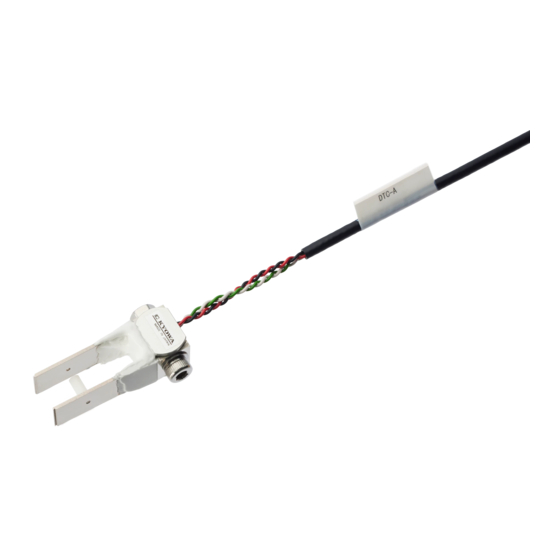
DTC-A Clip-type Displacement Transducer INSTRUCTION MANUAL
Thank you for purchasing this KYOWA product. Before using it,
read this instruction manual carefully. Also, keep the manual within
easy reach so that you can refer to it whenever necessary.
1. Calling the operator's attention
Be sure to observe the accompanying precautions preserve the
performance of the instrument.
Caution
It is a precaution to operate properly.
2. Handling precautions
Caution
Do not expand the space between the two beams or narrow it
even after they get in touch with the stoppers.
This product is exclusively designed for indoor use. When using
it, take care to avoid the direct rays of the sun, water, oil and
solvent.
Avoid measurement under vibration or impact.
Do not disassemble the displacement transducer.
3. Installation
The mounting sections of the transducer (the respective heads of
the two beams) are so designed that they confirm with the ASTM
(American Society for Testing & Materials) Standards E399. Use
the transducer properly by referring to the standards.
3.1 How to mount
On the measuring area, prepare two opposed grooves to
accept the transducer, or mount the transducer by screwing or
bonding two opposed tips (TIP-10A) (available as options) to
the transducer mounting section.(See Fig.3.1.1 and 3.1.2)
Fig.3.1.1 Configuration of groove on measuring object (ASTM Std.)
Fig.3.1.2 Configuration of tip (TIP-10A) (option)
When the two beams are free, the space between them is about
11mm. The measuring range is denoted by the space between the
mounting grooves. It is 4 to 9mm on DTC-A-5 and 8 to 10mm on
DTC-A-2. Fix the cable nearby the mainframe so that the mass of
the cable will not affect the transducer.
4. Connection and measurement
4.1 Connect the transducer to a strain amplifier.
4.2 Perform connection as illustrated below when using an NDIS
connector.
(The shield wire is not connected to the mainframe.)
4.3 It is required to heat-run for 5 to 10 minutes before starting the
measurement.
4.4 Measurement values increase in the PLUS direction as space
grows between the beams.
5. Conversion
5.1 Use the calibration constant described in the test data sheet to
convent a reading into a displacement value.
5.2 When a strain amplifier is in use, output reads in μm/m
equivalent strain (×10
equivalent strain). Find a displacement
-6
value corresponding to μm/m. Then, obtain a displacement
value through multiplication using the following equation.
Displacement value(mm)
=Strain amplifier's output (μm/m)
5.3 When using an amplifier of other type or a recorder, first find
the exact bridge exciting voltage applied. Second, find the
displacement value that corresponds to 1(μV) output voltage
against 1(V) bridge excitation voltage. Then, obtain the
displacement value through multiplication using the following
equation.
Displacement value(mm)
Bridge output voltage(μV)
=
Bridge excitation voltage(V)
6. Storage and inspection
6.1 Avoid water, oil and dust on the displacement transducer.
6.2 If an abnormal initial value or reading appears, measure input
resistance, output resistance as well as insulation resistance
(which should be 100M
and red to green.
If abnormal resistance is found, the cause may be failure of the
sensing element. In this case, contact your KYOWA
representative for necessary inspection.
Caution
To measure insulation resistance, apply a voltage lower than
50V to the insulation resistance tester.
When storing the transducer, be sure that it is free from
displacement.
Avoid storing the transducer where it is exposed to especially
high or low temperature or much dust.
IM-T-221B May,2018
Displacement transducer
×Calibration constant (mm/1μm/m)
×Calibration constant (mm/1μV/V)
or higher) between the main body
Advertisement

Related Manuals for KYOWA DTC-A


Summary of Contents for KYOWA DTC-A
- Page 1 When the two beams are free, the space between them is about 11mm. The measuring range is denoted by the space between the mounting grooves. It is 4 to 9mm on DTC-A-5 and 8 to 10mm on DTC-A-2. Fix the cable nearby the mainframe so that the mass of...
- Page 2 7. Dimensional drawing Fig.7.1 DTC-A-2 Fig.7.2 DTC-A-5 8. Specifications Models Rated Capacity (Bezel Distance) Measuring Force (Approx.) Natural Frequencies (Approx.) DTC-A-2 2mm (8 to 10mm) 4 to 20N 580Hz DTC-A-5 5mm (4 to 9mm) 1 to 10N 215Hz ◆ Performance Cable 4-conductor (0.08mm...
- Page 3 ブリッジ印加電圧(V) 6. 保管上の注意および点検 6.1 変位変換器には水,油,塵などがつかないようにしてく ださい。 図 3.1.1 被測定部の溝形状(ASTM 規格) 6.2 初期値,指示値が異常と思われる場合は,入力抵抗,出 力抵抗, 本体とケーブル心線間の絶縁抵抗 (100MΩ以上) を測定してください。 異常があれば本器の故障と考えられます。弊社の営業ま でご連絡ください。 注意 絶縁抵抗を測定する場合には,絶縁抵抗計の印加電圧は 50V 以下でご使用ください。 保管時は変位を与えないで保管してください。 特に湿度の高いところや低いところ,湿度の高いところや 塵埃の多いところでの保管は避けてください。 図 3.1.2 チップ(TIP-10A)形状(オプション) 2枚のビームの取付溝間隔は自由な状態で約 11mm となって います。測定範囲は DTC-A-5 が取付溝間隔 4~9mm,DTC-A-2 が取付溝間隔 8~10mm です。 ケーブルの質量が変換器本体に作用しないように本体の近く でケーブルを固定してください。...
- Page 4 7. 外形寸法図 図 7.1 DTC-A-2 図 7.2 DTC-A-5 8. 仕様 型式名 定格容量 測定力 (約) 固有振動数 (約) DTC-A-2 2mm(取付溝間隔 8~10mm 範囲) 4~20N 580Hz DTC-A-5 5mm(取付溝間隔 4~9mm 範囲) 1~10N 215Hz ◆性能 ◆機械的特性 定格容量 :表参照 許容過負荷 :130%(ストッパ付) 非直線性 :±1%RO 以内 固有振動数 :表参照 ヒステリシス...
Need help?
Do you have a question about the DTC-A and is the answer not in the manual?
Questions and answers