Advertisement
Quick Links
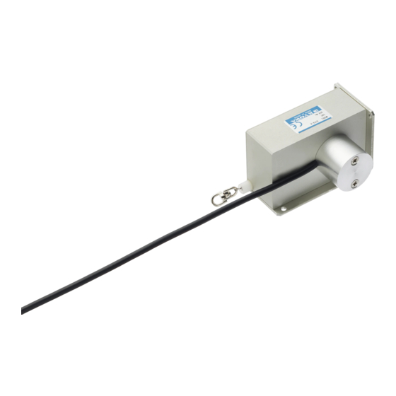
DTPA-A-5K Wire-type Displacement Transducer
Thank you for purchasing this KYOWA product. Before using it, read this
instruction manual carefully. Also, keep the manual within easy reach so that
you can refer to it whenever necessary.
Specifications and dimensions described in this manual could be changed
without notice. Please visit our website for the latest version.
1. Calling the operator's attention
The following cautionary symbols and headlines are used to invite the
operator's attention. Be sure to observe the accompanying precautions in
order to safeguard the operator and preserve the performance of the
instrument.
Improper handling may cause serious injury to the
Warning
operator.
Cautions are given to invite the operator's attention,
Caution
in order to avoid instrument failure or mal-function.
2. Important notice
Unless specified, strain-gage transducers must not be used under hydrogen
environment.
3. Safety precautions
The DTPA-A has the mechanism that winds the wire automatically.
As you release the wire, the DTPA-A winds the wire furiously and
damages your body. Do not release the wire you are holding.
4. Handling precautions
Caution
Do not release the wire you are holding. Also, do not apply sudden
shocks to the wire. Or, the product may be damaged.
Do not disassemble the displacement transducer.
Do not use the transducer where it may be exposed to water or much
dust.
Do not use the transducer in vibrations.
Make sure that the bending radius of cable is longer than 6 times of a
diameter of the cable.
5. Installation
5.1 Mount the DTPA-A onto the steady points (vertical or horizontal) by using
the hexagon socket head bolts (M4, L6 or more).
* Customers are required to purchase the hexagon socket head bolts.
INSTRUCTION MANUAL
Warning
5.2 The ZERO balance is -1.5 to -1.2 mV/V.
5.3 Make sure the rubber stopper is securely positioned in the guide. With
holding the rubber stopper with one hand, pull out the wire. If you release
the wire, the DTPA-A slowly winds the wire.
5.4 With the wire pulled out 5 to 20 mm, lock the swivel.
5.5 Remove the rubber stopper from the guide. Open the slit of the rubber
stopper and remove it from the wire.
6. Connection
6.1 Connect the transducer to a strain amplifier.
6.2 When using a strain amplifier other than KYOWA, wiring to the connector
plug should be made as illustrated.
6.3 It is required to heat-run for 5 to 10 minutes before starting the
measurement.
7. Conversion
7.1 Use the calibration constant described on the Test Data Sheet to convert
a measured value into a displacement value.
7.2 When a strain amplifier is in use, output reads in ×10
Find a displacement value corresponding to ×10
displacement value through multiplication using the following equation.
Displacement (mm) = Strain amplifier's output (×10
7.3 When using an amplifier of other type or a recorder, first find the exact
bridge exciting voltage applied. Second, find the displacement value that
corresponds to 1(μV) output voltage against 1(V) bridge excitation
voltage. Then, obtain the displacement value through multiplication using
the following equation.
Displacement (mm) =
Bridge output voltage (μV)
Bridge excitation voltage (V)
8. Maintenance and inspection
8.1 Avoid water, oil and dust on the displacement transducer.
8.2 Recommend calibrate the product once a year or so. (Contact your
KYOWA representative.)
8.3 If an abnormal initial value or reading appears, measure input resistance,
output resistance as well as insulation resistance (which should be
100M or more) between the main body and red to green.
If abnormal resistance is found, the cause may be failure of the sensing
element. In this case, contact your KYOWA representative for necessary
inspection.
Caution
To measure insulation resistance, apply a voltage lower than 50V to the
insulation resistance tester.
IM-T-296C Jul. 2021
-6
equivalent strain.
-6
strain. Then, obtain a
strain)
-6
x Calibration constant (mm / 1×10
×Calibration constant (mm / 1μV/V)
strain)
-6
Advertisement

Subscribe to Our Youtube Channel
Related Manuals for KYOWA DTPA-A-5K


Summary of Contents for KYOWA DTPA-A-5K
- Page 1 6.1 Connect the transducer to a strain amplifier. instrument. 6.2 When using a strain amplifier other than KYOWA, wiring to the connector plug should be made as illustrated. Improper handling may cause serious injury to the Warning operator.
- Page 2 4mm diameter by 3m Instruction manual 1 (This book) long, terminated with a connector plug * At the time of the purchase, one is attached to the product. PRC03-12A10-7M (Shield wire is not connected to the case.) Website : www.kyowa-ei.com...
- Page 3 IM-T-296C 2021.7 DTPA-A-5K型 ワイヤ式変位変換器-取扱説明書 5.3 ストッパゴムがしっかりとクチ座の奥まで入っているの このたびは本製品をお買い上げいただきまして, ありがとうご を確認したうえで,ストッパゴムを手で押さえながらワイ ざいます。ご使用の前には,本書を必ずお読みください。 ヤを引出してください。万が一,ワイヤから手を離しても また, お読みになったあとはいつでも見られるところに必ず保 管してください。 ワイヤがゆっくり巻き取られます。 5.4 ワイヤを5~20mm引出した状態でスイベルを固定してくだ 本書に記載の仕様は予告なく変更させていただく場合があり ます。最新情報は弊社ホームページをご確認ください。 さい。 5.5 ストッパゴムをクチ座から抜き出し,ストッパゴムの切れ 1. 取扱説明書中のマークについて 目を開いてワイヤから取り外してください。 ご使用になる方の安全確保に関する重要な事項や機能確保に 6. 接続・測定 関する事項にはマークをつけて記載していますので, 必ずお読 みください。 6.1 変位変換器をひずみ測定器に接続します。 6.2 弊社以外のひずみ測定器を使用される場合は,コネクタプ 取扱を誤った場合, 人体に重大な悪影響を及ぼ 警告 ラグへの配線は下図のようになっていますので確認のうえ す恐れがあります。 接続してください。...
- Page 4 (10 物質) (注)RoHS 指令対応品は, CE マークの表記付き製品に限ります。 ◆電気的特性 許容印加電圧 10V AC または DC ◆付属品 推奨印加電圧 1~5V AC または DC ストッパゴム(青色) 3個(※) 入力抵抗 350Ω±1% 検査成績書 1部 出力抵抗 205Ω±3% 取扱説明書 1部(本書) ケーブル 0.08mm ,4 心シールドクロロプレン 3m ※納入時,1個は製品に取り付けられています。 外径 4mm,先端コネクタプラグ PRC03-12A10-7M (シールドは本体に接続されていません) ホームページアドレス www.kyowa-ei.com...
Need help?
Do you have a question about the DTPA-A-5K and is the answer not in the manual?
Questions and answers