Table of Contents
Advertisement
Quick Links
Advertisement
Table of Contents
Troubleshooting

Related Manuals for Wood-mizer BMS500


Summary of Contents for Wood-mizer BMS500
- Page 1 Wood-Mizer ® Safety, Operation, Maintenance and Parts Manual Industrial Sharpener BMS500 Rev. A1.07 BMS600 Rev. A1.06 Read Safety concern! understand safety information instructions before operating, setting up and/or maintaining this machine. Form # 943...
-
Page 2: Table Of Contents
Oil Level........................3-1 Grinding Wheel Shaft Bearings................. 3-1 SECTION 4 PREPARING THE SHARPENER FOR SHARPENING VORTEX BLADES Grinding Wheel and Oiler Replacement ..............4-1 Cam Replacement...................... 4-4 Blade Pusher Adjustment ..................4-7 Sharpener Head Adjustment..................4-7 BMS500/600doc121319 Table of Contents... - Page 3 ....................8-24 8.19 Magnetic Filter (BMS600 Sharpener) ..............8-26 8.20 Alignment Tool & Blade ProfileTemplate .............. 8-27 8.21 Decal Kit........................8-28 8.22 3" Blade Supports Kit (Option) ................8-29 8.23 Table Extensions Kit (BMS600 Option) ............. 8-32 Table of Contents BMS500/600doc121319...
-
Page 4: Safety & General Information
Customer Service Representative to order more decals. Always properly dispose of all by-products, including debris, coolant and oil. Safety instructions are listed in this section by the following operations: Electrical Safety Blade Handling Machine Operation BMS500/600doc121319 Safety & General Information... -
Page 5: Electrical Safety
Secure all loose clothing and jewelry before operating this machine. Failure to do so may result in serious injury or death. WARNING! The sharpener should not be operated by persons allergic to ACP-1 oil or its vapors. Safety & General Information BMS500/600doc121319... -
Page 6: Sharpener Components
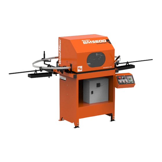
Safety & General Information Sharpener Components Sharpener Components See Figure 1-1. The major components of the BMS500/BMS600 Industrial Sharpener are shown below. Sharpener Main Cam & Index Arm Guard Drive Assembly Blade Support Arms Sharpener Head with Coolant Drip Pans... -
Page 7: Overall Dimensions
Model Length Width Height BMS500/BMS600 865mm 1202mm 1476mm (34") (47.32") (58.11") TABLE 1-1 See Figure 1-2. The figure below shows overall dimensions of the BMS500/BMS600 sharpener with the blade support arms installed. IS203_002a FIG. 1-2 Safety & General Information BMS500/600doc121319... -
Page 8: Noise Level
Safety & General Information Noise Level Noise Level See Table 1-2. The level of noise generated by the BMS500/BMS600 sharpener is given in the table below Max. Noise Level 80 dB (A) BMS500 BMS600 TABLE 1-2 Motor Specifications See Table 1-3. The grinder motor specifications are listed below. -
Page 9: Technical Data
Safety & General Information Technical Data Technical Data See Table 1-5. See the table below for technical data on the BMS500/BMS600 sharpener. Maximum Blade Width 76 mm (3") Grinding Wheel Main Shaft Speed 4280 rpm Feed Rate 0-64 teeth / min... -
Page 10: Control Panel Components
Controls cam rotational speed, i.e. number of sharpened teeth per minute. Rotate the dial as necessary to increase or decrease the cam speed. Cam Motor Start/Stop Switch Press "START" on the Cam Motor Start/Stop Switch to start the cam and index arm motor. BMS500/600doc121319 Safety & General Information... - Page 11 NOTE: Place the disconnect switch in the "0" position before opening the electric box door. To reconnect power to the machine, turn the switch to the vertical position ("1" - ON). Safety & General Information BMS500/600doc121319...
- Page 12 Safety & General Information Control Panel Components See Figure 1-4. The disconnect switch on the sharpener electric box is shown below. Disconnect Switch IS203_032 FIG. 1-4 BMS500/600doc121319 Safety & General Information...
-
Page 13: Safety Decals Description
Safety & General Information Safety Decals Description 1.10 Safety Decals Description See Table 1-7. See the table below for descriptions of the pictographic warning and informative decals placed on the BMS500/BMS600 sharpener. TABLE 1-7 Decal View Decal No. Description S10364-P2 "Hazardous voltage"... - Page 14 Close all guards and covers before starting the machine. 099220 095961 Use ACP-1 oil. 095961 S12004G-1 Always wear safety goggles when operating the sharpener! 512107 CAUTION! Always wear protective gloves when operating the sawmill 501467 Point of lubrication. 1-11 BMS500/600doc121319 Safety & General Information...
- Page 15 Safety & General Information Safety Decals Description TABLE 1-7 S20097K Direction of motor revolutions - 4280 r.p.m. s20097k 4280 RPM P85070 CE safety certification 524490 Clean the sharpener every 8 hours 524490 Safety & General Information BMS500/600doc121319 1-12...
-
Page 16: Setup & Operation
Fasten the sharpener to the floor using the mounting holes in the feet. The sharpener can be operated with an oil mist exhaust system only. The machine can be operated under roof only. BMS500/600doc121319 SETUP & OPERATION... - Page 17 230V [L1+L2 (230V phase-to-phase voltage)] (min. 15 AWG) BMS500B(S/U) 3 x 230V 10 Amp minimum 1.5 mm BMS600B(S/U) (min. 15 AWG) BMS500C(S/U) 3 x 460V 10 Amp minimum 1.5 mm BMS600C(S/U) (min. 15 AWG) TABLE 2-1 SETUP & OPERATION BMS500/600doc121319...
-
Page 18: Blade Support Arms Installation
3. The blade support guide assembly can be positioned at any location on the blade support arm, depending on the blade length. The side blade support arms can be adjusted horizontally if necessary. All blade support arms can be adjusted up or down, depending on the blade width. BMS500/600doc121319 SETUP & OPERATION... - Page 19 SETUP & OPERATION Blade Support Arms Installation See Figure 2-4. IS203_004 FIG. 2-4 SETUP & OPERATION BMS500/600doc121319...
-
Page 20: Blade Height Adjustment
Blade Height Adjustment Blade Height Adjustment The BMS500/BMS600 sharpener is equipped with a blade height adjustment assembly that allows smooth height adjustment of 1”(25 mm), 1 1/4” (31.25 mm), 1 1/2” (37.5 mm), 1 3/4" (43.75 mm), 2" (50mm) and 3" (75mm) wide blades. -
Page 21: Grinding Wheel Installation
SETUP & OPERATION Grinding Wheel Installation Grinding Wheel Installation Use a Wood-Mizer approved grinding wheel. To install the grinding wheel, perform the following steps: 1. Push the START button on the control box and turn the feed rate dial clockwise to rotate the cam. -
Page 22: Face Grind Adjustment
If the face grind is too heavy, turn the adjustment knob in, toward the other knob. 6. Check the face grind on the next tooth and adjust as needed. Face Grind Adjustment Knob IS203_033_A FIG. 2-6 BMS500/600doc121319 SETUP & OPERATION... - Page 23 SETUP & OPERATION Face Grind Adjustment See Figure 2-7. The figure below shows proper position of the grinding wheel in relation to the blade being sharpened. IS203_025_A FIG. 2-7 SETUP & OPERATION BMS500/600doc121319...
-
Page 24: Grind Depth Adjustment
2 passes, readjusting for blade height and face grind. IMPORTANT! After any adjustment, always restart the blade and sharpen in its entirety to ensure symmetry. NOTE: The grind depth may be affected as the grinding wheel passes through a blade weld. BMS500/600doc121319 SETUP & OPERATION... -
Page 25: Index Arm Stroke Adjustment
Stroke Adjustment Plate Mounting Screw (Hex Socket Head Cap) Indexer Shaft Stroke Adjustment Plate Indicator on Stroke Adjustment Plate Stroke Adjustment Plate Mounting Screw Indicator on Cam (Hex Socket Head Cap) IS203_031_A FIG. 2-9 tooth spacings: SETUP & OPERATION BMS500/600doc121319 2-10... -
Page 26: Oil Flow Adjustment
severe rust is present, the blade has tooth spacing uncommon to Wood-Mizer blades (i.e., a competitor’s blade) 2-11 BMS500/600doc121319 SETUP & OPERATION... -
Page 27: Sharpener Operation
The sharpener will automatically shut off when the blade has been entirely sharpened. Inspect the blade. Repeat the sharpening process if necessary. Blades with a bad profile or those which are badly in need of sharpening may have to be ground more than once. SETUP & OPERATION BMS500/600doc121319 2-12... -
Page 28: 3" Blade Support Setup (Option)
2.14 3" Blade Support Setup (Option) 1. Install the 3" blade guide assembly (1) on the sharpener mount plate (2) using the washers (3,4) and the bolts shown below (5). See Figure 2-10. IS203_040_A FIG. 2-10 2-13 BMS500/600doc121319 SETUP & OPERATION... - Page 29 3. Position the blade support kits so that the blade is not too loose and moves freely during the sharpening operation. 4. The blade supports should be adjusted vertically so that the bottom of the blade is at the same height along entire length of the blade. SETUP & OPERATION BMS500/600doc121319 2-14...
-
Page 30: Replacement Of Components
Oil Level Periodically check the oil level. Add oil as necessary. The oil level should be kept between 8.5 and 10 litres. Use only Wood-Mizer approved oil. Filter the oil to remove metal shavings before reusing. Grinding Wheel Shaft Bearings Periodically check the grinding wheel shaft bearings for wear and replace as necessary. - Page 31 7. Remove the multi-groove drive belt. 8. Remove the pulley from the spindle. 9. Remove the hole plug mounting nuts. 10. Remove the bolts mounting the spindle to the machine body. 11. Dismount the complete sharpener spindle. Replacement of Components BMS500/600doc121319...
- Page 32 31. Install the grinding wheel and tighten the mounting nut to 44.2 fl-lbs (60Nm) torque. 32. Mount and set the oiler. 33. Mount the grinding wheel side guard. Once bearing replacement is complete, be sure to check head alignment. BMS500/600doc121319 Replacement of Components...
-
Page 33: Preparing The Sharpener For Sharpening Vortex Blades
Grinding Wheel and Oiler Replacement 1. Unscrew the wing screws (B) and dismount the grinding wheel cover (A). FIG. 4-1 2. BMS500: unbolt the mounting hardware (A) and remove the oiler (B). FIG. 4-2 Preparing the sharpener for sharpening VORTEX bladesISHdoc121319... - Page 34 Preparing the sharpener for sharpening VORTEX blades Grinding Wheel and Oiler Replacement 3. BMS600: unbolt the mounting hardware (B) and dismount the oiler inside block (A). FIG. 4-3 4. Remove the nut (B) and dismount the grinding wheel (A). Then install the grinding wheel No.
- Page 35 Preparing the sharpener for sharpening VORTEX blades Grinding Wheel and Oiler Replacement 5. BMS500: install the oiler No. 522705 (B) using the mounting hardware (A). FIG. 4-5 6. BMS600: mount the oiler inside block - Part No. 523669 (A) using the mounting hardware (B).
-
Page 36: Cam Replacement
Preparing the sharpener for sharpening VORTEX blades Cam Replacement 7. Using the wing screws (B), install the grinding wheel cover (A). FIG. 4-7 Cam Replacement 1. Dismount the pusher (B) by removing the pusher shaft (A) from the cam. FIG. 4-8 ISHdoc121319 Preparing the sharpener for sharpening VORTEX... - Page 37 Preparing the sharpener for sharpening VORTEX blades Cam Replacement 2. Unscrew the three screws shown below (B) and remove the stroke adjustment plate (A). FIG. 4-9 3. Dismount the cam (A) by removing the two bolts shown below (B). Next, remove the magnet (C) from the cam and fasten it to the new cam (Part No.
- Page 38 Preparing the sharpener for sharpening VORTEX blades Cam Replacement 4. Fasten the stroke adjustment plate (A) to the cam using the three screws shown below (B). FIG. 4-11 1. Install the pusher (B) by screwing the pusher shaft (A) into the cam. FIG.
-
Page 39: Blade Pusher Adjustment
Preparing the sharpener for sharpening VORTEX blades Blade Pusher Adjustment Blade Pusher Adjustment Using the adjustment nuts (A), adjust the blade pusher (B) so that it pushes the next tooth after the tooth to be sharpened. FIG. 4-13 Sharpener Head Adjustment Use the bolt shown below (A) to raise the sharpener head (B) by 3 to 4 mm. -
Page 40: Maintenance & Troubleshooting
MAINTENANCE & TROUBLESHOOTING Sharpener Maintenance SECTION 5 MAINTENANCE & TROUBLESHOOTING Sharpener Maintenance DANGER! Swarf (metal filings) must be cleaned and removed from the oil pan and filter magnets every 8 hours of operation to avoid possi- ble fire. Failure to do so may result in death or serious injury. Daily (after end of the shift): Remove the blade, wipe the sharpener dry, lower the head, close the guard and unplug the ... - Page 41 MAINTENANCE & TROUBLESHOOTING Sharpener Maintenance CAUTION! Regularly clean or replace the filter of the oil vapours exhaust system (according to the manufacturer’s recommendations). MAINTENANCE & TROUBLESHOOTING doc121319...
-
Page 42: Blade Sharpening Tips
MAINTENANCE & TROUBLESHOOTING Blade Sharpening Tips Blade Sharpening Tips This section covers some of the common problem areas of blade sharpening. Before removing from the sawmill, clean the blade by running the water lube on it for 15 seconds. This will remove most of the sap buildup that would otherwise have to be scraped off when it dries. Then wipe the blade with a clean, dry rag. -
Page 43: Drive Belt Tension
MAINTENANCE & TROUBLESHOOTING Drive Belt Tension Drive Belt Tension The drive belt should be tightened to 0.33" (8.5 mm) deflection with 4.5 pounds (20N) of deflection force. See Figure 5-1. IS203_027 FIG. 5-1 MAINTENANCE & TROUBLESHOOTING doc121319... - Page 44 MAINTENANCE & TROUBLESHOOTING Drive Belt Tension See Figure 5-2. Loosen the nuts on the grinder motor mounting bolts. Turn the lower tensioning bolt clockwise and the upper tensioning bolt counterclockwise to tighten the drive belt. Turn the upper tensioning bolt clockwise and the lower tensioning bolt counterclockwise to loosen the drive belt. Grinder Motor Mounting Nuts, 4 pcs Upper Tensioning...
-
Page 45: Counter Troubleshooting
MAINTENANCE & TROUBLESHOOTING Counter Troubleshooting Counter Troubleshooting PROBLEM CAUSE SOLUTION "POWER DEFAULT" message Power supply interruption Press the START button; the appears on the display counter will resume counting the interrupted sharpening cycle. Press the RESET button; the counter will restore the last saved number of teeth and cycles. -
Page 46: Alignment
ALIGNMENT Sharpener Alignment SECTION 6 ALIGNMENT Align the sharpener monthly to ensure quality performance. Besides, realign the sharpener whenever it is necessary (i.e., after the grinding wheel has been impacted by the index arm). Sharpener Alignment Use the provided alignment tool as necessary to achieve accurate alignment between the blade clamp and the grinding wheel. - Page 47 ALIGNMENT Sharpener Alignment See Figure 6-1. Position the tool so that all three set screws touch the fixed blade clamp plate. Reinstall the grinding wheel mounting nut and tighten to secure in place. I S 2 0 3 _ 0 2 3 _ B Alignment Tool Sharpener Head...
- Page 48 ALIGNMENT Sharpener Alignment See Figure 6-2. Sharpener Head Mounting Bolts IS203_024A FIG. 6-2 7. Remove the grinding wheel mounting nut and the alignment tool. 8. Install the moving blade clamp plate. 9. Install the grinding wheel and secure in place with the mounting nut. 10.
-
Page 49: Sharpener Head Stop Adjustment
ALIGNMENT Sharpener Head Stop Adjustment Sharpener Head Stop Adjustment To prevent the saw head from hitting the blade clamp, when there is not blade in the clamp, adjust the distance between the grinding wheel and the clamp. To do that, lower the sharpener head all the way down by rotating the cam. -
Page 50: Blade Handling
Blade Handling Coiling The Blade SECTION 7 BLADE HANDLING This section covers coiling the blade, uncoiling the blade and inverting the blade. WARNING! Always wear gloves and eye protection when handling bandsaw blades. Keep people away from work area when coiling or moving blades. Coiling The Blade See Figure 7-1. - Page 51 Blade Handling Coiling The Blade See Figure 7-2. Keeping your wrists locked in position, turn your forearms upward and inward. (The teeth will rotate inward and the bottom of the blade will rotate outward.) FIG. 7-2 See Figure 7-3. Bring your hands together. The blade will form three loops. Snap the bot- tom loop upward and catch the three-loop coil in your hands.
-
Page 52: Uncoiling The Blade
Blade Handling Uncoiling The Blade Uncoiling The Blade See Figure 7-4. Take the three-loop coil in your right hand. Place the band against your palm with the blade teeth pointing outward toward your fingers. Slide the top loop off and let drop. - Page 53 Blade Handling Uncoiling The Blade See Figure 7-6. Keeping the blade in its crossed position, take hold of the side crossed UNDER with your other hand. Use your right (or left) hand to hold only the side crossed OVER. Place your thumbs on the top side of the blade. Put your fingers on the under- neath side of the blade.
-
Page 54: Inverting The Blade
Blade Handling Inverting The Blade Inverting The Blade See Figure 7-8. Hold the blade in front of you. Let one side rest on the ground, teeth pointing toward you. Place you thumbs on the outside of the blade. Put your fingers on the inside of the blade. - Page 55 Blade Handling Inverting The Blade See Figure 7-10. Keeping your hands close together, rotate the curved section of the blade up and away from you. The blade will be in an oval shape, but twisted. FIG. 7-10 See Figure 7-11. Slowly move your hands apart, allowing the blade to untwist. FIG.
-
Page 56: Storing Blades
Blade Handling Storing Blades Storing Blades Use care when moving, storing, or handling blades. When blades are stacked or thrown together, the tips can be dulled or the set changed. Stack two blades back-to-back using dividers between each set of blades to prevent the teeth from contacting each other. -
Page 57: Replacement Parts
Nagórna 114 St, Poland at +48-63-2626000. From the continental U.S., call our U.S. Headquarter 8180 West 10th St.Indianapolis, IN 46214, toll-free at 1-800-525-8100. Have your customer number, vehicle identification number, and part numbers ready when you call. From other international locations, contact the Wood-Mizer distributor in your area for parts. Office Hours:... -
Page 58: Stand Assembly
REPLACEMENT PARTS Stand Assembly Stand Assembly IS203_006_B REF. DESCRIPTION ( Indicates Parts Available In Assemblies Only) PART # STAND, BMS500/600 SHARPENER - COMPLETE 101264 STAND, BMS500/600 SHARPENER 101265-1 CAP, SR 1540 OUTRIGGER LEG 089710 WIRE HOUSING, SHARPENER BASE 500465 SCREW, M4x12 -5.8-B CROSS RECESSED PAN HEAD F81011-43 WASHER 4.3 FLAT ZINC... - Page 59 REPLACEMENT PARTS Stand Assembly FOOT, ADJUSTABLE SHARPENER 101238-1 PLATE, CLAMPING M10-ZINC 101242-1 BOLT, M10x70-8.8-HEX HEAD FULL THREAD ZINC F81003-20 NUT, M10-8-B-HEX ZINC F81033-3 WASHER, 10.5 FLAT ZINC F81055-1 BOLT, M10x25-8.8 HEX HEAD FULL THREAD ZINC F81003-11 SUPPORT, HEAD COVER - COMPLETE 500468 SUPPORT, HEAD COVER 500461-1...
-
Page 60: Cover Assembly
REPLACEMENT PARTS Cover Assembly Cover Assembly IS203_007B REF. DESCRIPTION ( Indicates Parts Available In Assemblies Only) PART # COMPLETE SHARPENER COVER 100850 SHARPENER COVER 100851-1 HINGE, COVER 088257 GRIP, LONG HANDLE 086164 SEAL WIRE, GH6 085338 PIPE, FUME EXHAUST CONNECTION 087974-1 VIEWFINDER, TOP COVER 505180... - Page 61 REPLACEMENT PARTS Cover Assembly BOLT, M6x35 8.8 HEX HEAD ZINC F81001-71 SCREW, M4x20 8.8 HEX SOCKED HEAD ZINC F81011-31 NUT, M4-B HEX NYLON ZINC LOCK F81029-1 NUT, M6-8-B HEX NYLON ZINC LOCK F81031-2 WASHER, 4.3 FLAT ZINC F81051-2 WASHER, 6.4 FLAT ZINC F81053-1 REPLACEMENT PARTS doc121319...
-
Page 62: Blade Support Assembly
REPLACEMENT PARTS Blade Support Assembly Blade Support Assembly IS203_005 REF. DESCRIPTION ( Indicates Parts Available In Assemblies Only) PART # BLADE SUPPORT, SIDE COMPLETE 101261 SUPPORT, BLADE SIDE ZINC 100844-1 BRACKET, BLADE SIDE SUPPORT 101247-1 WASHER, 13 SPECIAL FLAT F81056-14 KNOB, SR1580, 80X40 M12 100848 KNOB, SR1580 63x25 M12... -
Page 63: Additional Blade Support Assembly (Option)
REPLACEMENT PARTS Additional Blade Support Assembly (Option) SUPPORT, BLADE COMPLETE BACK 101262 PIPE, SUPPORT 087584-1 REST WELDMENT, BLADE 101243-1 KNOB, 63mm M12x25 SR 1580 500460 PIPE, BLADE WEAR REAR 087590 WASHER, 13 SPECIAL FLAT ZINC F81056-14 NUT, M12-04-A HEX THIN ZINC F81034-6 NUT, M12-8-B HEX ZINC F81034-1... -
Page 64: Rear Blade Guide (Option)
REPLACEMENT PARTS Rear Blade Guide (Option) Rear Blade Guide (Option) REF. DESCRIPTION ( Indicates Parts Available In Assemblies Only) PART # GUIDE, REAR BLADE - COMPLETE 525322 BASE, BLADE GUIDE ZINC-PLATED 525323-1 BRACKET, BLADE GUIDE ROLLER ZINC-PLATED 525325-1 CHANNEL, CLAMPING ZINC-PLATED 525328-1 CHANNEL, BLADE GUIDE ZINC-PLATED 525330-1... -
Page 65: Side Blade Guide (Option)
REPLACEMENT PARTS Side Blade Guide (Option) Side Blade Guide (Option) REF. DESCRIPTION ( Indicates Parts Available In Assemblies Only) PART # GUIDE, SIDE BLADE - COMPLETE 527137 BASE, BLADE GUIDE ZINC-PLATED 525323-1 CHANNEL, CLAMPING ZINC-PLATED 525328-1 CHANNEL, BLADE GUIDE ZINC-PLATED 525330-1 WASHER, 8.4 FLAT ZINC F81054-1... -
Page 66: Electric Box
REPLACEMENT PARTS Electric Box Electric Box IS203_008 REF. DESCRIPTION ( Indicates Parts Available In Assemblies Only) PART # CONTROL BOX, SHARPENER BMS500AU 101141-M21 CONTROL BOX, SHARPENER BMS500BS 101141-M2 CONTROL BOX, SHARPENER BMS500CU 101141-M4 CONTROL BOX, SHARPENER BMS500HS 101141-M CONTROL BOX, SHARPENER BMS600AU 101141-M21 HD CONTROL BOX, SHARPENER BMS600BU 101141-M2 HD... -
Page 67: Control Panel
REPLACEMENT PARTS Control Panel Includes components listed in 8.10 Electrical Component List, BMS500C. Includes components listed in 8.14 Electrical Component List, BMS500HS. Includes components listed in 8.16 Electrical Component List, BMS600AU. Includes components listed in 8.18 Electrical Component List, BMS600BU. Includes components listed in 8.20 Electrical Component List, BMS600CU. -
Page 68: Coolant Tank
WASHER, 6.4 FLAT ZINC F81053-1 8.11 Coolant Tank IS203_010 REF. DESCRIPTION ( Indicates Parts Available In Assemblies Only) PART # TANK, BMS500/600 SHARPENER COOLANT - COMPLETE 101245 TANK, COOLANT 100839-1 BOLT, M10x80-8.8 HEX HEAD ZINC F81003-50 NUT, M10-8-B HEX NYLON ZINC LOCK F81033-1 WASHER, 10.5 FLAT ZINC... -
Page 69: Mounting Plate
REPLACEMENT PARTS Mounting Plate 8.12 Mounting Plate IS203_011 REF. DESCRIPTION ( Indicates Parts Available In Assemblies Only) PART # PLATE, SHARPENER MOUNTING - COMPLETE 100843 PLATE, MOUNTING ZINC 100837-1 BOLT, M10x1x25 DIN 933 F81003-28 BOLT, M12x25-8.8-HEX HEAD FULL THREAD ZINC F81004-31 NUT, M10x1-04-ST-A2 ISO 8675 THIN F81033-10... -
Page 70: Sharpener Head
Sharpener Head 8.13 Sharpener Head IS203_012C 100780_Manual REF. DESCRIPTION ( Indicates Parts Available In Assemblies Only) PART # HEAD, BMS500 SHARPENER - COMPLETE 100781 HEAD, BMS600 SHARPENER - COMPLETE 100781-RS HOUSING, SHARPENER HEAD 100782-1 SPINDLE, BMS500/600 SHARPENER - COMPLETE 100785... - Page 71 Grinding Wheel, 8" 7°/39.5° 1.25"TS 0.4"TH CBN 077703 OILER,CBN 8" - SHARPENER STANDARD 100805 OILER, CBN 8" 0.875"TS-1.25"TS, BMS 500 SHARPENER 101235 OILER, SHARPENER BMS500 - VORTEX 522705 DECAL KIT, GRINDING WHEEL ROTATION S20097K SEAL, G1/4 PD13 090809 FITTING, WES 10/R 1/4 ELBOW...
- Page 72 F81080-1 For BMS500 Sharpener only. Belongs to Sharpener Decal Kit BMS500 - 500467. Belongs to BMS600 Only. For BMS600 units needing to process 1 1/4” tooth spacing add one 505673-1 to the left side of the BMS600 1 1/8” oiler.
-
Page 73: Cam & Index Arm Drive Assembly
0 0 7 8 0 _ M a n REF. DESCRIPTION ( Indicates Parts Available In Assemblies Only) PART # CAM & INDEX ARM DRIVE ASSEMBLY 100820 CAM, BMS500/600 SHARPENER ZINC-PLATED 509734-1 PLATE, STROKE ADJUSTMENT ZINC 511878-1 COMPLETE PUSH PAWL 083942 WASHER, Z12.2 SPLIT LOCK ZINC... - Page 74 REPLACEMENT PARTS Cam & Index Arm Drive Assembly RING, W22 INSIDE RETAINING F81090-7 WASHER, 8.4 FLAT ZINC F81054-1 NUT,M8-8-B,HEX,NYLON LOCK ZINC F81032-2 PAWL WELDMENT, BLADE INDEX - ZINC 100814-1 SCREW, M8x8 45H HEX SOCKET SET FLAT POINT F81014-1 PUSHER, BLADE COMPLETE 093358 WASHER, 5.3 FLAT ZINC F81052-1...
-
Page 75: Sharpener Head Lever
REPLACEMENT PARTS Sharpener Head Lever 8.15 Sharpener Head Lever IS203_014 REF. DESCRIPTION ( Indicates Parts Available In Assemblies Only) PART # SHARPENER HEAD LEVER - COMPLETE 100809 SPACER 087965-1 BEARING, 6301-DDU (NSK) ROLLING 100816 LEVER, ANGLE ZINC-PLATED 100817-1 BEARING ASSEMBLY, UCP 203 CX 101108 BOLT, 12/M10x25 12.9 ISO7379 F81003-84... -
Page 76: Clamp And Coolant Wiper
8.16 Clamp and Coolant Wiper IS203_015D 14 15 REF. DESCRIPTION ( Indicates Parts Available In Assemblies Only) PART # CLAMP ASSEMBLY WITH HEIGHT ADJUSTMENT, COMPLETE BMS500 101225 CLAMP ASSEMBLY WITH HEIGHT ADJUSTMENT, COMPLETE BMS600 101225-RS PLATE, FIXED CLAMP ZINC 101229-1... - Page 77 REPLACEMENT PARTS Clamp and Coolant Wiper BOLT, M10x25-8.8-HEX HEAD FULL THREAD ZINC F81003-11 WASHER, 791 M10/10.5 RIBBED LOCK F81055-7 PIN, 4x30 SPRING-TYPE STRAIGHT ZINC-PLATED F81044-7 PIN, PN-EN ISO8752-4X20 ST AOP ROLL F81044-11 NUT, M16x1.5-08-B-ZINC HEX THIN F81036-6 NUT, BLADE HEIGHT ADJUSTMENT 101254 SCREW, M8x30-8.8 HEX SOCKET HEAD CAP ZINC F81002-31...
-
Page 78: Deburr Assembly
REPLACEMENT PARTS Deburr Assembly 8.17 Deburr Assembly 14 15 IS203_017 REF. DESCRIPTION ( Indicates Parts Available In Assemblies Only) PART # DEBURR ASSEMBLY 100824 PLATE, MOUNTING DEBURR ZINC-PLATED 100825-1 SHAFT, PIVOT ARM ZINC 100826-1 ARM, PIVOT ASSEMBLY 100828 ARM, PIVOT ZINC-PLATED 100827-1 BEARING, 6000 2RSR NR. - Page 79 REPLACEMENT PARTS Deburr Assembly NUT, M10-8-B HEX NYLON ZINC LOCK F81033-1 BOLT, M5x15 BN1006 (BOSSARD) TURNED EYE F81000-30 NUT, M5-8-HEX ZINC F81030-1 WASHER, 10.5 FLAT ZINC F81055-1 BOLT, M10x25-8.8-HEX HEAD FULL THREAD ZINC F81003-11 NUT, M10-8-B HEX NYLON ZINC LOCK F81033-1 SPRING, 1.6x12x38 EXTENSION 092208...
-
Page 80: Magnetic Filter
FILTER, BMS500 MAGNETIC - COMPLETE 101269 TANK, MAGNETIC FILTER 101270-1 SEAL, RUBBER WIRE INSIDE DIA. 26MM 085613 MAGNET, 100X30X15 FILTER 516192 PAN, BMS500/600 SHARPENER FILTER - COMPLETE 101249 PAN WELDMENT, BMS500/600 SHARPENER FILTER 101251 HANDLE, 4" W/BOLTS P08065 BOLT, #8-32X3/8 SELF -TAPPING F05015-8... - Page 81 REPLACEMENT PARTS Magnetic Filter REF. DESCRIPTION ( Indicates Parts Available In Assemblies Only) PART # TUBE, 90$ Z GW BSP/GZ BSPT 1" (EE-1/13-16 TUBES) ZINC-PL. 517294 VALVE, SENA PN 25 RHGC3 BALL 517293 REPLACEMENT PARTS doc121319 8-25...
-
Page 82: Magnetic Filter (Bms600 Sharpener)
FILTER, BMS600 SHARPENER MAGNETIC - COMPLETE 101269-RS TANK, MAGNETIC FILTER 505665-1 SEAL RUBBER, WIRE INSIDE DIA. 26MM 085613 MAGNET, 1 00X30X15 FILTER 516192 PAN, BMS500/600 SHARPENER FILTER - COMPLETE 101249 PAN WELDMENT, BMS500/600 SHARPENER FILTER 101251 HANDLE, 4" W/BOLTS P08065 BOLT, #8-32X3/8 SELF-TAPPING F05015-8... -
Page 83: Alignment Tool & Blade Profiletemplate
REPLACEMENT PARTS Alignment Tool & Blade ProfileTemplate 8.20 Alignment Tool & Blade ProfileTemplate REF. DESCRIPTION ( Indicates Parts Available In Assemblies Only) PART # ALIGNMENT TOOL, SHARPENER BMS500/600 505190 TOOL, BMS500/600 ALIGNMENT ZINC-PLATED 504890-1 SCREW, M8x40-45H HEX SOCK.SET CONE POINT F81002-52... -
Page 84: Decal Kit
REPLACEMENT PARTS Decal Kit 8.21 Decal Kit REF. DESCRIPTION ( Indicates Parts Available In Assemblies Only) PART # DECAL KIT, BMS500 SHARPENER 500467 DECAL, BMS500 SHARPENER 500801 DECAL, GENERAL WARNING 086362 DECAL, EYE WARNING, SMALL S12004G-1 DECAL, ELECTRIC POWER SIGN S10364-P2 DECAL, READ OPERATOR’S MANUAL... -
Page 85: 3" Blade Supports Kit (Option)
3" Blade Supports Kit (Option) 8.22 3" Blade Supports Kit (Option) is203_038 REF. DESCRIPTION ( Indicates Parts Available In Assemblies Only) PART # SUPPORT KIT, BMS500/600 3" BLADE 505584 GUIDE, 3" BLADE COMPLETE 503790 PLATE, 3" BLADE GUIDE ZINC-PL. 503791-1... - Page 86 PAN WLDMT, OIL DRIP 101257-1 GROMMET, 1'' ID RUBBER P11765 PLUG, B-1/4-KU (BST R 1/4") 087605 TUBE, BLADE SUPPORT SPACER - COMPLETE 505576 TUBE, BMS500/600 SIDE EXTENSION ZINC-PL. 502405-1 CAP, 1530 DIA. 18x2 100847 BLOCK, SPACER TUBE CONNECTION - COMPLETE 505577 8-30 doc121319...
- Page 87 REPLACEMENT PARTS 3" Blade Supports Kit (Option) BLOCK, SPACER TUBE CONNECTION ZINC-PL. 505578-1 HANDWHEEL, 40 DIA./M8x20 (462053 MOSS) 500973 REPLACEMENT PARTS doc121319 8-31...
- Page 88 REPLACEMENT PARTS Table Extensions Kit (BMS600 Option) 8.23 Table Extensions Kit (BMS600 Option) IS203_041 REF. DESCRIPTION ( Indicates Parts Available In Assemblies Only) PART # TABLE EXTENSIONS KIT, BMS600 (OPTION) 508838 LEG, ADJUSTABLE HIGH - COMPLETE 508845 LEG, ADJUSTABLE HIGH 508844-1 PLATE, M10 ZINC 101242-1...
- Page 89 EC declaration of conformity according to EC Machinery Directive 2006/42/EC, Annex II, 1.A Manufacturer: Wood-Mizer Industries sp. z o.o. Nagórna 114, 62- Tel. +48 63 26 26 000 This declaration of conformity is issued under the sole responsibility of the manufacturer.
Need help?
Do you have a question about the BMS500 and is the answer not in the manual?
Questions and answers