Table of Contents
Advertisement
Quick Links
Advertisement
Table of Contents

Subscribe to Our Youtube Channel
Related Manuals for Wood-mizer LT15WC E15


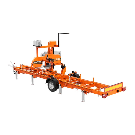
Summary of Contents for Wood-mizer LT15WC E15
- Page 3 Wood-Mizer ® Safety, Installation, Operation and Maintenance LT15WC E15 rev. A1.09 LT15WC G25 rev. A1.09 Safety is our #1 concern! Read and understand all safety information and instructions before oper- ating, setting up or maintaining this machine. Form #790...
-
Page 4: Table Of Contents
Table of Contents Section-Page SECTION 1 SAFETY INSTRUCTIONS Safety Symbols..................1-1 Blade Handling..................1-2 Sawmill Setup..................1-2 Sawmill Operation..................1-2 Sawmill Maintenance ................1-4 Safety Instructions ..................1-4 Belt Sizes ....................1-12 Blade Sizes ...................1-12 Cutting Capacity...................1-12 1.10 Engine/Motor Specifications ..............1-13 1.11 Noise Level...................1-14 1.12 Sawdust Exhaust System Specifications ..........1-14 1.13 Overall Dimensions ................1-15 1.14... - Page 5 Table of Contents Section-Page SECTION 4 MAINTENANCE Wear Life....................4-1 Sawdust Removal ...................4-1 Carriage Track & Rollers ...............4-1 Vertical Mast Rails .................4-2 Miscellaneous Lubrication ..............4-2 Blade Wheel Belts ..................4-3 Brake Pads Adjustment ( Gas / Diesel Sawmills Only ) ......4-4 Up/Down and Feed System ..............4-4 Miscellaneous Maintenance ..............4-8 4.10 Filling Blade Tensioner Cylinder with Oil..........4-8...
- Page 6 IMPORTANT! Read the entire Operator’s Manual before operating the sawmill. Take notice of all safety warnings throughout this manual and those posted on the machine. Keep this manual with this machine at all times, regardless of ownership. G24doc091522...
- Page 7 G24doc091522...
- Page 8 Getting Service Wood-Mizer is committed to providing you with the latest technology, best quality and strongest customer service available on the market today. We continually evaluate our customers’ needs to ensure we’re meeting current wood-processing demands. Your comments and suggestions are welcome.
- Page 9 Branches & Authorized Sales CentersWood-Mizer Locations (North and South America) EUROPE UNITED STATES European Headquarters World Headquarters Wood-Mizer Industries Sp. z o.o. Wood-Mizer LLC Nagórna 114, 62-600 Koło, Poland 8180 West 10th Street Tel.: +48-63-26-26-000 Indianapolis,Indiana 46214-2400, Fax: +48-63-27-22-327 www.woodmizer.eu Tel.: +1-317-271-1542...
- Page 10 CROATIA Krešimir Pregernik ITALY Pasquale Felice SERBIA Dragan Markov Pregimex d.o.o. Wood-Mizer Italia Srl Wood-Mizer Balkan d.o.o. S. Batušiæa 31, 10090 Zagreb Cda. Capoiaccio SN Svetosavska GA 3/3; P. Fah 25 Tel.:/Fax: +3851-38-94-668 86012 Cercemaggiore 23 300 Kikinda Krešimir Pregernik Campobasso Tel.:/Fax: +381-230-25-754...
- Page 11 Robert Moxham DENMARK Kevin Christiansen TRANSILVANIEI Nr. 5 Regional Direction - Asia Kevin Christiansen's Sibiu, Cisnadie 555300 Wood-Mizer Asia Manufacturing Co., Ltd. savværker PMV Tel.:/Fax: : +40-369-405-433 No.2, Gongyequ 40th Rd. Xitun District, Arnborgvej 40, 7330 Brande- Fasterholt GSM: +40-745-707-323 Taichung City, 40768, Taiwan, R.O.C.
-
Page 12: Safety Instructions
Always be sure that all safety decals are clean and readable. Replace immediately all damaged safety decals to prevent personal injury or damage to the equipment. Contact Wood-Mizer Customer Service or the Wood-Mizer distributor in your area to order a new decal. IMPORTANT! -
Page 13: Blade Handling
Blade Handling Blade Handling DANGER! Always disengage the blade and shut off the sawmill motor before changing the blade. Failure to do so will result in serious injury. WARNING! Always wear gloves and eye protection when handling bandsaw blades. Keep all other persons away from area when coiling, uncoiling, carrying or changing a blade Changing blades is safest when done by one person! Failure to do so may result in serious injury. - Page 14 Sawmill Operation DANGER! Always be sure the blade is disengaged and all persons are out of the path of the blade before starting the engine or motor. Failure to do so may result in serious injury. WARNING! Always wear eye, ear, respiration and foot protection as well as safety clothing when operating or servicing the machine.
-
Page 15: Sawmill Maintenance
All Wood-Mizer owners are encouraged to become thoroughly familiar with these applicable laws and comply with them fully while using the sawmill. All Wood-Mizer sawmill owners are encouraged to become thoroughly familiar with these applicable laws and comply with them fully while using the machine. - Page 16 Wear Safety Clothing Wear Safety Clothing WARNING! Secure all loose clothing and jewelry before operating the sawmill. Failure to do so may result in serious injury or death. WARNING! Always wear gloves and eye protection when handling bandsaw blades. Changing blades is safest when done by one person! Keep all other persons away from area when coiling, carrying or changing a blade.
- Page 17 Check Sawmill Before Operation Check Sawmill Before Operation DANGER! Make sure all guards and covers are in place and secured before operating the sawmill. Failure to do so may result in serious injury. Keep Persons Away DANGER! Keep all persons out of the path of moving equipment and lumber when operating the sawmill.
- Page 18 Use Proper Maintenance Procedures WARNING! Use extreme caution when spinning the blade wheels by hand. Make sure your hands are clear of the blade and wheel spokes before spinning. Failure to do so may result in serious injury. Use Proper Maintenance Procedures DANGER! Make sure all electrical installation, service and/or maintenance work is performed by a qualified electrician and is in...
- Page 19 Keep Safety Labels In Good Condition Keep Safety Labels In Good Condition IMPORTANT! Always be sure that all safety decals placed on the machine are clean and readable. Replace all damaged safety decals to prevent personal injury or damage to the equipment. Jeśli zatem nalepka jest uszkodzona, to należy natychmiast wymienić...
- Page 20 Keep Safety Labels In Good Condition TABLE 1-1 099219 Blade tension. Turning the bolt clockwise will increase the blade tension, and turning the bolt counterclockwise will decrease the tension. 099219 099221 CAUTION! Keep all persons away from the machine during sawmill operation. 099221 098176 CAUTION! Keep away from the debarker...
- Page 21 Keep Safety Labels In Good Condition TABLE 1-1 096319 CAUTION! Disconnect power supply before opening the box. 096321 Blade movement direction S12004G CAUTION! Always wear safety goggles when operating the sawmill! S12005G CAUTION! Always wear protective ear muffs when operating the sawmill! 501465 CAUTION! Always wear safety boots when operating the sawmill!
- Page 22 Keep Safety Labels In Good Condition TABLE 1-1 501467 Lubrication point P11789 Tracking the blade on the blade wheels 510643 Setting the blade tension indicator 510643 1015-1088 70-75 1088-1160 75-80 80-85 1160-1233 P85070 CE certification marking 099401 Russian safety certification 099401 S20097F 2925 r.p.m.
-
Page 23: Belt Sizes
Each additional bed frame segment adds approximately 195 cm to length capacity. See table 1-4. The performance capacity of the LT15WC sawmill is listed below. Sawmill Model Cutting Rate LT15WC E15, G25 3.3 m/min. TABLE 1-4 Safety Instructions 15doc091522 1-12... -
Page 24: Engine/Motor Specifications
Engine/Motor Specifications 1.10 Engine/Motor Specifications See table 1-5. See the table below for specifications of the engine used on the LT15WC AC sawmills. Engine/Motor Type Manufacturer Model Number Other Data Electric Motor 11 kW Indukta, Poland PSg-132S-2_H132 3 x 400V, 50 Hz Up/Down Motor, 0.55 kW Besel SKh71X-4C2/HPS08... -
Page 25: Noise Level
1.11 Noise Level See table 1-8. The average level of noise generated by the LT15WC sawmill is given in the table below Sawmill Noise Level: LT15WC E15 = 87 dB (A) LT15WC G25 = 96 dB (A) TABLE 1-8 1.12 Sawdust Exhaust System Specifications See table 1-9. -
Page 26: Overall Dimensions
Overall Dimensions 1.13 Overall Dimensions See Figure 1-1. The overall dimensions of the LT15WC sawmill are shown below. FIG. 1-1 1-15 15doc091522 Safety Instructions... - Page 27 Overall Dimensions See Figure 1-2. The overall dimensions of the LT15WC sawmills with M type frames are shown below. FIG. 1-2 Safety Instructions 15doc091522 1-16...
- Page 28 Overall Dimensions See Figure 1-3. The overall dimensions of the LT15WC sawmills with S type frames are shown below. FIG. 1-3 1-17 15doc091522 Safety Instructions...
- Page 29 Overall Dimensions See Figure 1-4. The legs layout of the LT15WC sawmills with S type frames is shown below. FIG. 1-4 Safety Instructions 15doc091522 1-18...
- Page 30 Overall Dimensions See Figure 1-5. See the figure below for the operator’s work-place. LT15WC_oper_01 FIG. 1-5 1-19 15doc091522 Safety Instructions...
-
Page 31: Components
Components 1.14 Components The major components of the LT15WC sawmill are shown below. See Figure 1-6. Water Tank Up/Down Drive Assembly Saw Head Sawmill Mast Blade Tension Handle Blade Motor Blade Guide Arm Handle Log Clamp Electric Box Control Box Blade Guide Sawmill Frame FIG. -
Page 32: Sawmill Assembly
Mounting Parts of LT15WC Sawmills with Electric Motors SECTION 2 SAWMILL ASSEMBLY Scan to see the assembly video. Mounting Parts of LT15WC Sawmills with Electric Motors 2.1.1 Parts specifications Table 1: Fig. Wood-Mi Descrip- Qty. Qty. zer No. tion LT15 LT15 LT15 LT15... - Page 33 Parts specifications Table 1: 086172-1 Bottom Bracket 531670 Track Wiper 086659-1 Frame Mounting Strap, Zinc-plated 086745 Middle Track Cover with Felt Wiper 092378-1 Bracket, Blade Guide Roller Guard 092379-1 Blade Guide Roller Guard 093859 Plate, PC Guard 094250-1 Track Rail, Zinc-plated (Short) 095490-1...
- Page 34 Parts specifications Table 1: 506287-1 Plate, Bed Section Connector 507565 Log Clamp Bracket, 508236-1 Feed Cable Mount - Front 508237-1 Bracket, Feed Cable Mount - Rear 538799-1 Track Rail (LT15S3) 538935-1 (LT15M2) LTBGAT Tool, Blade Guide Alignment R02080 Rope 11.4 Vertical Mast Lock Assembly 086743-1 Zinc-plated...
- Page 35 Parts specifications Table 1: F81058-1 Washer, 17 Manual Feed Assembly 538949-1 Power Feed Crank Handle 094142 Bushing 086338 Crank Han- dle Grip F81033-1 Hex Nylon Lock Nut Power Feed Assembly 544323 Chain 7456 MM 587-link 550808 Chain 7010 MM 552-link (LT15WC- 550807 Chain...
- Page 36 501414-1 Plate, Power Feed Sup- port 086182-1 Mount Weldment , Saw Head Stop P12165 Bushing, Rubber 2.1.2 Specifications of Fasteners Table 2: Wood-Mizer No. Description Qty. Qty. LT15 LT15 LT15 LT15 LT15 LT15 LT15 LT15 S3-P S4-P Designations of fasteners: M8 Nut 8.4 Washer...
- Page 37 Tools Necessary for Assembling the Sawmill Table 2: F81003-15 Bolt, M10x75 F81003-2 Bolt, M10x30 5.8 F81003-2 Bolt, M10x30 8.8 F81003-66 Bolt, M10x90 F81004-12 Bolt, M12-55-8.8 F81004-35 Bolt, M12x140 F81004-36 Bolt, M12x130 F81004-38 Bolt, M12x120 F81030-2 Nut, M5 F81031-2 Nut, M6-8-B F81032-2 M8 Nut F81033-1...
-
Page 38: Unpacking The Sawmill
Unpacking the Sawmill Table 3: Required tools Flat Wrench #10 2 pcs Flat Wrench #13 2 pcs Flat Wrench #17 2 pcs Flat Wrench #19 2 pcs Ratchet Wrench #30 1 pcs Hammer 1 pcs Allen Wrench #4 1 pcs Allen Wrench #5 1 pcs Unpacking the Sawmill... -
Page 39: Bed Frame Assembly
Bed Frame Assembly WARNING! When removing the saw head, use extreme care and keep all persons at a safe distance. Failure to do so may result in serious injury or death. See figure 2-2. 500kg 150167B FIG. 2-2 Bed Frame Assembly IMPORTANT! With all screw joints without split lock washer or lock nylon nut, use the “LOCTITE 243”... - Page 40 Bed Frame Assembly See figure 2-3. M10 Hex Nylon Lock Nut 094427-1 (LT15S3) 094696-1 (LT15M2) 10.5 Washer Bolt, M10x75 FIG. 2-3 15doc091422 SAWMILL ASSEMBLY...
- Page 41 Bed Frame Assembly 2. Outrigger legs - Mount four (or six) support brackets (A) to each bed section with two M10x75 hexagon head bolts (B) and lock nuts (C). Make sure the nut on the bracket faces up. Thread legs (D) into each bracket and secure them with nuts (E).
- Page 42 Bed Frame Assembly 3. Lay the frame sections end-to-end so the track portion of each section is on the same side. Slide the sections together and secure with four hex head bolts and nylon lock nuts. See figure 2-5. “M” Bed Frame Bolt, M10x30-5.8 Hex Head Full Thread Zinc (4pcs)
- Page 43 Bed Frame Assembly 4. Fasten the track rails together using the frame mounting straps, on the outside of the frame (see the figure above). Secure each strap to the track rail with two hex head bolts. Tighten the track rail mounting nuts.
- Page 44 Bed Frame Assembly 5. Mount a bed extension to the front and the rear ends of the bed frame. See figure 2-6. “M” Bed Frame 10.2 Split Lock M12 Hex Nylon Lock Washer Bolt, M10x75 086659-1 10.5 Washer 094250-1 Bolt, M10x30-5.8 Hex Head Full Thread 13 Flat M12x120...
- Page 45 Bed Frame Assembly 6. Assemble a log clamp to a bed rail on each bed section using the existing hex head bolts and nylon lock nuts. 7. Install the log side supports as shown in Figure 2-7. Tighten the nuts so that the side supports can be moved with little resistance.
-
Page 46: Saw Head Assembly
Possibility of sawmill bed and service bed section connection. 2.3.1 Possibility of sawmill bed and service bed section connection. 1. Possibility of S and M-type sawmill bed (manufactured before 1st of September 2020) and S and M type versatile bed sections connection. See figure 2-8. - Page 47 Saw Head Assembly See figure 2-9. FIG. 2-9 2. Position the middle track cover between the two track roller housings so the opening in the cover is positioned over the feed rope pulleys. Secure with two hex head bolts and lock washers. 3.
- Page 48 Saw Head Assembly See figure 2-10. 8.4 Flat Washer (4) M8x12 Hex Head Bolt (4) Track Wiper Śr FIG. 2-10 NOTE: Before installing the middle track cover and the remaining felt wipers, soak the felt strips with lubricating fluid (e.g. Mineral Oil). 4.
- Page 49 Saw Head Assembly See figure 2-11. Spring 087301 086743-1 Cotter Pin Washer F81043-2 F81058-1 FIG. 2-11 5. Install the PC operator guard. See figure 2-12. M8x16 Bolt 8.4 Washer M10x50 Bolt 10.5 Washer FIG. 2-12 SAWMILL ASSEMBLY 15doc091422 2-18...
- Page 50 Saw Head Assembly 6. Install the blade guides. See figure 2-13. Blade Guide 094682 Blade Guide 094683 M10x1x25 Bolt M10x1 (8) Flat Washer FIG. 2-13 2-19 15doc091422 SAWMILL ASSEMBLY...
- Page 51 Saw Head Assembly 7. Cut the control box mounting mounting strips in travel position. Adjust the control box in operation position and use the mounting bolts to mount it. See figure 2-14. 150199 Control box in travel position 150200 Control box in operation position FIG.
- Page 52 Saw Head Assembly 8. Turn the power feed motor from the travel position to the work position. The motor should be posi- tioned as shown in the figure below. Tighten the motor mounting screws. See figure 2-15. Motor Mounting Screws FIG.
-
Page 53: Manual Feed Rope Assembly
Manual Feed Rope Assembly 9. Install the power cord bracket. See figure 2-16. Hanger, Power Cord 086132-1 FIG. 2-16 10. Adjust the cam engaging the limit switch as well as the saw head stop bolt, See Section , step 3-8. Manual Feed Rope Assembly 1. - Page 54 Manual Feed Rope Assembly See figure 2-17. 10.5 Flat Washer 089689-1 Nut M10 FIG. 2-17 2. Tie a knot in one end of the feed rope. Slip the knotted end of the rope into the front rope mount bracket. Route the rope between the saw head and main bed frame tube. 2-23 15doc091422 SAWMILL ASSEMBLY...
- Page 55 Manual Feed Rope Assembly See figure 2-18. FIG. 2-18 3. Loop the rope around the inner groove of the lower v-groove roller and route to the feed crank spool. See figure 2-19. 150111 FIG. 2-19 4. Loop the rope around the feed crank spool three times and route back down to the outer v-groove roller.
- Page 56 Manual Feed Rope Assembly See figure 2-20. 150112 FIG. 2-20 2-25 15doc091422 SAWMILL ASSEMBLY...
- Page 57 Manual Feed Rope Assembly 5. Route the rope around the outer groove of the v-groove roller. See figure 2-21. 150113 FIG. 2-21 6. Route the rope to the rear mounting bracket. Tie a knot in the end of the rope and insert into the rear mounting bracket.
-
Page 58: Power Feed Chain Assembly
Power Feed Chain Assembly Power Feed Chain Assembly 1. Before installation of the chain, make sure the power feed motor is properly positioned in relation to the gear box, as shown in the figure below. If not, turn the motor until it is in the operation position. Secure the motor to the gear box with the mounting screws. - Page 59 Power Feed Chain Assembly 2. Screw 544321 and 544320 elements to the bed frame as shown in the picture. 10.5 Washer 10.2 Split Lock Washer M10x30 Hex Screw Chain Tensioner - Right 3. Screw the mounting bracket (544313-1) to the bed frame with F81002-141 screws and 556625-1 spacer sleeves.
- Page 60 Power Feed Chain Assembly 4. Screw 550433-1 plate to the motor. Power Feed Motor In Operation Posi- tion 5. Screw the complete assembly to the bed frame with F81002-5 bolts as shown in the figure below. 2-29 15doc091422 SAWMILL ASSEMBLY...
- Page 61 Power Feed Chain Assembly 6. Attach the chain at the end of the bed frame as shown in the picture SAWMILL ASSEMBLY 15doc091422 2-30...
- Page 62 Power Feed Chain Assembly 7. Pass the chain through the sprockets as shown in the figure and attach the chain at the other end of the bed frame. 8. Tighten the chain at both ends with the nuts. 2-31 15doc091422 SAWMILL ASSEMBLY...
-
Page 63: Auxiliary Bed Rail
Auxiliary Bed Rail Auxiliary Bed Rail To install the auxiliary bed rail to a bed frame section, use the set of mounting holes provided between the two bed rails. Remove the existing bolt and lock nut that secures the track at this posi- tion. -
Page 64: Installation Of The Fuel Hoses
Installation of the Fuel Hoses Installation of the Fuel Hoses The fuel hoses should be placed on the sawmill mast as shown in the photos below. 2-33 15doc091422 SAWMILL ASSEMBLY... -
Page 65: Setup & Operation
Sawmill Setup SECTION 3 SETUP & OPERATION Sawmill Setup IMPORTANT! Before starting to use the sawmill you have to meet the following conditions: Set up the machine on firm and level ground. Level the sawmill. Secure the sawmill to the ... - Page 66 Sawmill Setup See table 3-1. 3-Phase Volts Circuit Breaker Suggested Wire Size 400 VAC 32 A 4 mm Maximum length: 15 m TABLE 3-1 IMPORTANT! When starting the machine for the first time, check that main motor rotation direction is as indicated by the arrow located on the motor body.
- Page 67 Sawmill Setup See figure 3-1. Equal height object Measure distance between string and bed rails Equal height String across object bed rails FIG. 3-1 4. Repeat the bed rail adjustment with the string at the other side of the sawmill frame. 5.
- Page 68 Sawmill Setup When the blade is parallel to bed, it will measure the same distance from the bed rail See figure 3-2. at the inside and outside of the saw head. If not, adjust the saw head tilt. To do this, loosen the four mounting bolts (A) and use the saw head adjustment nut (B).
- Page 69 Sawmill Setup See figure 3-4. Clip alignment tool to blade Przypiąć przyrząd regulacyjny do piły FIG. 3-4 Move the saw head so the front end of the tool is positioned over the first bed rail. Measure the distance from the bottom of the tool to the top surface of the bed rail. Move the saw head so the front end of the tool is positioned over the bed rail.
- Page 70 Sawmill Setup See figure 3-5. To tilt the idle-side blade wheel up, loosen the bottom adjustment screw 1/2 turn. Loosen the nut on the top adjustment screw and tighten the top adjustment screw. Then tighten the upper and lower nut. To tilt the wheel down, loosen the top adjustment screw 1/2 turn.
- Page 71 Sawmill Setup the top adjustment screw and tighten the screw. Tighten the top and bottom jam nuts. To tilt the wheel up, tighten the top screw (loosening the bottom one). To tilt the wheel down, tighten the bottom screw (loosening the top one). 150075-1f Alignment Tool...
- Page 72 Sawmill Setup 15. Bolt the blade guide guard, so that its bottom edge is about 5mm above blade. FIG. 3-7 15doc091422 Setup & Operation...
-
Page 73: Replacing The Blade
Replacing The Blade See figure 3-8. Adjust the cam engaging the limit switch as well as the saw head stop bolt so that the saw head stops moving at its lower travel limit - at the height of 25 mm above the bed. Loosen the nut and adjust the stop bolt Loosen bolts and adjust cam... -
Page 74: Tensioning The Blade
Tensioning The Blade Position 1 1/4” wide blades on the wheels so the gullet is 3 mm out from the front edge of the wheel. Position 1 1/2” wide blades on the wheels so the gullet is 4.5mm out from the front edge of the wheel. -
Page 75: Tracking The Blade
Tracking The Blade CAUTION! Release the blade tension when the sawmill is not in use (e.g.: at the end of the shift). It should be also an information on the sawmill, that the blade should be tensioned before starting. Tracking The Blade 1. -
Page 76: Starting The Engine/Motor
Starting the Engine/Motor See figure 3-11. To adjust where the blade travels on the blade wheels, use cant control bolt. Cant Control Bolt FIG. 3-11 If the blade is too far out, back the blade onto the wheel by turning the cant control bolt counterclockwise. If the bade is too far in, turn the cant control bolt clockwise until the gullet of the blade is the correct distance from the front edge of the wheel. -
Page 77: Loading, Turning And Clamping Logs
Loading, Turning and Clamping Logs DANGER! Always be sure the blade is disengaged and all persons are out of the path of the blade before starting the engine or motor. Failure to do so may result in serious injury. WARNING! Always wear eye, ear, respiration and foot protection as well as safety clothing when operating or servicing the machine. - Page 78 Loading, Turning and Clamping Logs See figure 3-12. FIG. 3-12 2. Be sure to leave crank in the bottom position to avoid damage to the blade. See figure 3-13. sm0379_A FIG. 3-13 3. Make sure the side supports are positioned low enough for the blade to pass over them. If they are not, back the clamps off slightly and push the side supports down until they are positioned below the height of your last on a given side of the log.
- Page 79 Loading, Turning and Clamping Logs To level a log: Use the optional wedge to raise either end of a tapered log, if desired. Shim one end of the log until the heart of the log measures the same distance from the bed rails at each end of the log. See figure 3-14.
-
Page 80: Up/Down Operation
Up/Down Operation Optional manual toe board. If adjustment is necessary, mount the crank in the toe board fixture at the end of a log to be raised. Turn the crank clockwise to raise the end of the log. Raise the appropriate end of the log until the distance from the heart of the log to the bed rail is equal on both sides See figure 3-15. -
Page 81: Blade Guide Arm Operation
Blade Guide Arm Operation See figure 3-16. Use the up/down button (on the control panel) shown below to raise or lower the saw head. To raise the saw head press up but- ton. To lower the saw head press down button. FIG. -
Page 82: Blade Drive Operation
Blade Drive Operation See figure 3-17. Move the handle right to move the blade arm out. Move it left to move the blade guide in. FIG. 3-17 Blade Drive Operation DANGER! Make sure all guards and covers are in place and secured/closed before operating the sawmill. - Page 83 Blade Drive Operation - Press AND HOLD the green safety button on the control box. NOTE: Keep the safety button pressed all the time the blade is driven. If the safety button is released, the motor stops and it needs to be restarted. - Press the START button on the control box to start the motor.
-
Page 84: Feed Operation
Feed Operation See figure 3-19. The tensioner handle is located next to the engine. To engage the blade, push the clutch handle forward. 15B026-2C FIG. 3-19 4. To engage the blade, press the safety switch with your left hand and hold it down. Then push the tensioner handle forward until it locks in upper position. - Page 85 Feed Operation See figure 3-20. Turn the crank clockwise for forward feed; counterclockwise to return the saw head 150122C FIG. 3-20 HINT: To get a straight cut in the first part of the board, feed the blade into the log at a slow speed.
- Page 86 Feed Operation 3.10.2 Optional Electric Feed System The power feed system includes an electric motor with gear which moves the saw head using a steel strand. The speed at which the saw head travels forward is adjusted by the feed rate switch. See figure 3-21.
-
Page 87: Cutting The Log
3.11 Cutting The Log The following steps guide you through normal operation of the Wood-Mizer sawmill. 1. Once the log is placed where you want it and clamp firmly, position the blade close to the end of the log. -
Page 88: Edging
Edging 3.12 Edging The following steps guide you through edging boards on the Wood-Mizer sawmill. 1. Raise the side supports to 1/2 the height of the boards that need to be edged. 2. Stack these boards on edges against the side supports. - Page 89 Blade Height Scale Scale The horizontal red line on the blade height indicator shows how many centimeters the bottom of the blade is above the bed of the mill. If you know the height of your blade at each cut, you can determine the thickness of lumber you are sawing.
-
Page 90: Water Lube Operation
Water Lube Operation 3.14 Water Lube Operation The Water Lube System keeps the blade clean. Water flows from a 5-gallon (18.9 liter) bottle through a hose to the blade guide where the blade enters the log. A valve in the bottle cap controls the amount of water flow. -
Page 91: Transporting The Sawmill
Transporting the Sawmill 3.15 Transporting the Sawmill The assembled sawmill can be transported in an appropriately equipped pickup truck. 1. Adjust the saw head up just far enough so it will clear the sides of your truck bed when loaded. Do not adjust the saw head so high that the sawmill will tip easily while being loaded. - Page 92 Wood-Mizer LT15WCSC/LX100/LX450 Short Interval Maintenance Schedule (Check Engine And Option Manuals For Additional Maintenance Proce- dures) PROCEDURE MANUAL REFERENCE EVERY BLADE CHANGE SEE SECTION 4.2 Check blade guide roller performance SEE SECTION 4.2 Remove excess sawdust from blade wheel housings and sawdust chute EVERY 8 HOURS OF OPERATION SEE SECTION 4.3...
- Page 93 WOOD-MIZER LT15WCSC/LX100/LX450 MAINTENANCE LOG (Check Engine And Option Manuals For Additional Maintenance Procedures) PROCEDURE MANUAL REF- TOTAL HOURS OF OPERATION ERENCE FILL IN THE DATE AND THE MACHINE HOURS AS YOU PERFORM EACH PROCEDURE. A SHADED BOX INDICATES MAINTENANCE IS NOT NEEDED AT THIS TIME.
- Page 94 WOOD-MIZER LT15WCSC/LX100/LX450 MAINTENANCE LOG (Check Engine And Option Manuals For Additional Maintenance Procedures) PROCEDURE MANUAL REF- TOTAL HOURS OF OPERATION ERENCE FILL IN THE DATE AND THE MACHINE HOURS AS YOU PERFORM EACH PROCEDURE. A SHADED BOX INDICATES MAINTENANCE IS NOT NEEDED AT THIS TIME.
- Page 95 WOOD-MIZER LT15WCSC/LX100/LX450 MAINTENANCE LOG (Check Engine And Option Manuals For Additional Maintenance Procedures) PROCEDURE MANUAL REF- TOTAL HOURS OF OPERATION ERENCE FILL IN THE DATE AND THE MACHINE HOURS AS YOU PERFORM EACH PROCEDURE. A SHADED BOX INDICATES MAINTENANCE IS NOT NEEDED AT THIS TIME.
-
Page 96: Maintenance
Wear Life SECTION 4 MAINTENANCE This section lists the maintenance procedures that need to be performed on LT15WC sawmills. CAUTION! Always disconnect and lock out power supply before per- forming any maintenance work, cleaning or servicing the sawmill. Failure to do so may result in serious injury. This section lists the maintenance procedures that need to be performed. -
Page 97: Vertical Mast Rails
Vertical Mast Rails transmission fluid, 10W30 motor oil or 3-in-1 turbine oil every 25 hours of operation. FIG. 4-1 Vertical Mast Rails Clean and lubricate the vertical mast rails every 50 hours of operation. Clean with solvent and remove any rust with a light-grade sand paper. Lubricate the mast with motor oil or automatic transmission fluid (e.g. -
Page 98: Blade Wheel Belts
Blade Wheel Belts See figure 4-2. Grease Tensioner Threads 10_016_D FIG. 4-2 Blade Wheel Belts 1. Check the blade wheel belts for wear. Replace belts if necessary. Rotating the belts every 50 hours will increase the belt life. Use only B57 belts manufactured by Goodyear or Browning. 2. -
Page 99: Brake Pads Adjustment ( Gas / Diesel Sawmills Only )
Brake Pads Adjustment ( Gas / Diesel Sawmills Only ) Brake Pads Adjustment ( Gas / Diesel Sawmills Only ) Check the brake pads for wear every 200 hours of operation. Replace if damaged or worn. Adjust the brake pads if the blade does not stop quickly, unusual sounds occur when the brake is applied, or a sudden change is noticed in the clutch/brake lever position when the clutch is disengaged. - Page 100 Up/Down and Feed System See figure 4-3. Upper Limit Switch Up/Down Screw Bellows Lower Bearing Housing Lower Limit Switch FIG. 4-1 2. Lubricate the up/down acme screw with a rolling bearing lubricant (e.g. ŁT4S or Shell Extreme Pressure Grease) every six months. Apply the lubricant to the grease fitting in the nut housing. Lubrication may be required sooner if environmental conditions require it.
- Page 101 Up/Down and Feed System See figure 4-4. Unbolt the up/down top guard. Loosen the motor mounting bolts. Use the adjustment bolt shown below to adjust the belt tension. Retighten the engine mounting bolts. Reinstall the cover. Force=25N Adjustment Bolt Deflection= Motor mounting bolts FIG.
- Page 102 Up/Down and Feed System 1. Electromagnet body 2. Coil 3. Nut 4. Armature 5. Brake disk 6. Gear wheel 7. Mounting disk 8. Spring 9. Thrust pin 10. Mounting bolt 11. Adjustment bolt 12. Brake casing 13. Manual release lever 14.
-
Page 103: Miscellaneous Maintenance
Miscellaneous Maintenance Miscellaneous Maintenance 1. Check the drive belt tension after the first 20 hours and every 50 hours thereafter. See Section 6.13 for drive belt adjustment instructions. 2. Check the mill alignment every setup. (See Section 6, Alignment). 3. Make sure all safety warning decals are readable. Remove sawdust and dirt. Replace any damaged or unreadable decals immediately. - Page 104 Filling Blade Tensioner Cylinder with Oil of the oiler tube / hose is at the bottom of the cylinder. 4. Wait 5 minutes. If the oil level does not lower, move on to the next step. If the oil level lowers, top up the oil level until the oil flows out of the cylinder.
-
Page 105: Lt15Wc Ac Safety Devices Inspection (Only Ce Version)
LT15WC AC Safety Devices Inspection (Only CE Version) 5. Seal the oil pressure gauge with Teflon tape and screw it back. 4.11 LT15WC AC Safety Devices Inspection (Only CE Version) LT15WC AC - Safety devices inspection Safety devices on the LT15WC AC sawmill which must be checked before every shift: E-STOP button and its circuit inspection ... - Page 106 LT15WC AC Safety Devices Inspection (Only CE Version) Motor Start Button Debarker On/Off Switch Debarker Arm In/Out Switch Safety Button Power Feed Switch Up/Down System Emergency Buttons Stop Button 2 Green safety button inspection Be sure the E-STOP button is released; ...
-
Page 107: Lt15Wc Dc Safety Devices Inspection (Only Ce Version)
LT15WC DC Safety Devices Inspection (Only CE Version) With E-STOP button pressed try to move the saw head up and down (using the switch and Setworks button and forward/backward using the power feed switch. Both systems should not start. With E-STOP button pressed, try to start the debarker blade motor and move the debarker ... - Page 108 LT15WC DC Safety Devices Inspection (Only CE Version) Restarting the engine should not be possible until the E-STOP button is released. Up/Down System Button Safety Button Power Feed Emergency Switch Stop Button 2 Green safety button inspection Be sure the E-STOP button is released; ...
- Page 109 LT15WC DC Safety Devices Inspection (Only CE Version) With the E-STOP button pressed, try to move the saw head up and down (using the switch and the Setworks buttons) and forward/backward using the power feed switch. Both systems should not start. 4 Inspection of the tensioner handle safety switch Start the engine according to your engine option manual;...
-
Page 110: Troubleshooting Guide
Sawing Problems SECTION 5 TROUBLESHOOTING GUIDE Sawing Problems PROBLEM CAUSE SOLUTION Blades Dull Quickly Dirty logs Clean or debark logs, especially on entry side of the cut. When grinding, teeth heating too Grind just enough metal to restore much and causing teeth to soften. sharpness to the teeth. - Page 111 Sawing Problems PROBLEM CAUSE SOLUTION Boards Thick Or Thin On Stress in log which causes log to After log has been squared, take equal Ends Or Middle Of Board not lay flat on the bed cuts off opposing sides. Repeat cuts, keeping the heart in the middle of the cant, and making it your last cut.
-
Page 112: Sawmill Alignment
Pre-Alignment Procedures SECTION 6 SAWMILL ALIGNMENT Pre-Alignment Procedures Periodically check the sawmill alignment and adjust if necessary. This chapter explains how to align the entire sawmill. Care should be taken in performing these steps. Sawmill alignment determines the accuracy and squareness of your cuts. -
Page 113: Blade Wheel Alignment
Blade Wheel Alignment 5. Gas Engine Only: Release the clutch handle to stop the blade. Turn off the engine, remove the key and check the position of the blade on the blade wheels. Check the vertical alignment of the idle-side blade wheel. The gullet of the blade should ride the same distance from the front edge of the wheel at the top and bottom of the wheel. - Page 114 Blade Wheel Alignment See figure 6-2. Clip alignment tool to blade Przypiąć przyrząd regulacyjny do piły FIG. 6-2 2. Move the saw head so the front end of the tool is positioned over the first bed rail. Measure the distance from the bottom of the tool to the top surface of the bed rail. 3.
- Page 115 Blade Wheel Alignment See figure 6-3. Use the screws shown below to adjust the drive blade wheel vertically. To tilt the wheel down, loosen the top adjustment screw a half turn. Loosen the jam nut on the bottom adjustment screw and tighten the screw. Tighten the top and bottom jam nuts. To tilt the wheel up, loosen the bottom adjustment screw a half turn.
- Page 116 Blade Wheel Alignment Adjust vertical adjustment screws up to tilt idle-side blade wheel down; Adjust screws down to tilt wheel up 150075-2_E FIG. 6-4 8. Recheck the vertical tilt of the idle-side blade wheel. If it is still incorrect, repeat the adjustment procedure.
- Page 117 Blade Wheel Alignment Blade 1 1/4” FIG. 6-5 See figure 6-6. Use the cant control adjustment to adjust the idle-side blade wheel. If the blade is too far forward on the wheel, turn the cant control counterclockwise. If it is too far back on the wheel, turn the cant control clockwise.
-
Page 118: Blade Guide Arm Alignment
Blade Guide Arm Alignment adjustment. Adjustment Screw 150127B FIG. 6-7 NOTE: It is not necessary to align the spring bolt (bolt M10x75 [WM# F81003-15] + spring + washer) shown in the figure above. When replacing the bolt or spring just screw in the bolt maximally. Blade Guide Arm Alignment Before aligning the blade guide arm, track the blade on the blade wheels as described in Section... - Page 119 Blade Guide Arm Alignment See figure 6-8. 150128_C Adjust front top and bottom screws Adjust rear top and bottom screws with arm closed with arm open FIG. 6-8 2. Use the arm adjustment screws, marked with blue arrows in the figure above, to adjust the arm up until the slide pad touches the saw head brace tube.
-
Page 120: Aligning The Blade Guides
FIG. 6-9 Aligning The Blade Guides Each Wood-Mizer sawmill has two blade guide assemblies that help the blade maintain a straight cut. The two blade guide assemblies are positioned on the saw head to guide the blade on each side of the material being cut. -
Page 121: Blade Deflection
Blade Deflection Blade Deflection Perform the following steps to achieve proper blade deflection with the blade guides: 1. Raise the saw head until the blade is 15" (375 mm) above a bed rail. Measure the actual distance with a tape from the top of the rail to the bottom of the blade. See figure 6-10. - Page 122 Blade Guide Vertical Adjustment See figure 6-11. Clip alignment tool to blade Przypiąć przyrząd regulacyjny do piły FIG. 6-11 3. Measure the distance from the bottom of the tool to the bed rail. 4. Move the saw head so that the front end of the tool is positioned above the bed rail. 5.
-
Page 123: Blade Guide Spacing
Blade Guide Spacing 8. This measurement should equal the two earlier measurements. If it is not the same, adjust the blade guide using the screws shown in the figure above. 9. Move the tool close to the other blade guide and repeat the previous steps. NOTE: If any adjustments to blade guide tilt were made, make sure the blade deflection is correct (6 mm). -
Page 124: Horizontal Tilt Adjustment
Horizontal Tilt Adjustment 6.10 Horizontal Tilt Adjustment 1. Adjust the blade guide arm half way in. See figure 6-14. Turn side set screws Obrócić odpowiednio boczne wkręty to adjust horizontal tilt dociskowe by wyregulować ustawienie prowadnika w płaszczyźnie pionowej FIG. 6-14 2. -
Page 125: Blade Height Scale Adjustment
Blade Height Scale Adjustment See figure 6-15. Side Support Śruba regulacyjna Adjustment Bolt oporki bocznej FIG. 6-15 2. Swing a side support up so that it is vertical. 3. Pull back at the top of the support to eliminate slack as if a log were being clamped against it. 4. -
Page 126: Motor Drive Belt Adjustment
Motor Drive Belt Adjustment See figure 6-16. FIG. 6-16 1. Move the saw head so the blade is positioned directly above one of the bed rails. Measure from the bottom edge on a down-set tooth of the blade to the top of the bed rail (or stainless steel rail cover, if equipped). -
Page 127: Track Roller Distance Adjustment
Track Roller Distance Adjustment of E15 motor. Retighten the engine mounting bolts. Adjustment Śruby Bolts regulacyjne Motor Mounting Śruby mocujące Bolts (4) silnika (4) FIG. 6-17 6.14 Track Roller Distance Adjustment Using the screw (1), adjust the distance between the track roller (2) and the track rail (3) so that the mast can move freely. - Page 128 Track Roller Distance Adjustment See figure 6-18. FIG. 6-18 6-17 doc091522 Sawmill Alignment...
-
Page 129: Motor Brake
Motor Brake Motor Brake Maintenance SECTION 7 MOTOR BRAKE Motor Brake Maintenance Maintenance intervals Service brakes after 4000 hours of operation at the latest or every six months TABLE 7-1. IMPORTANT! Brakes with defective armature plates, cheese head screws, springs or flanges must be replaced completely. Please observe the following for inspections and maintenance operations: Remove impurities through oil and grease using brake cleaning agents, if necessary, replace brake ... - Page 130 Motor Brake Motor Brake Maintenance If necessary, adjust the air gap to "s ". Lürated Brake type sLürated sLümax Max. Rotor thickness Excess of the +0.1mm Service adjustment adjuster nut max. min. -0.05mm brake permissible wear [mm] [mm] Emax. [mm] INTORQ BFK458-25 0,4 mm...
- Page 131 EC declaration of conformity according to EC Machinery Directive 2006/42/EC, Annex II, 1.A Manufacturer: Wood-Mizer Industries sp. z o.o. Nagórna 114, 62- Tel. +48 63 26 26 000 This declaration of conformity is issued under the sole responsibility of the manufacturer.
Need help?
Do you have a question about the LT15WC E15 and is the answer not in the manual?
Questions and answers