Advertisement
Quick Links
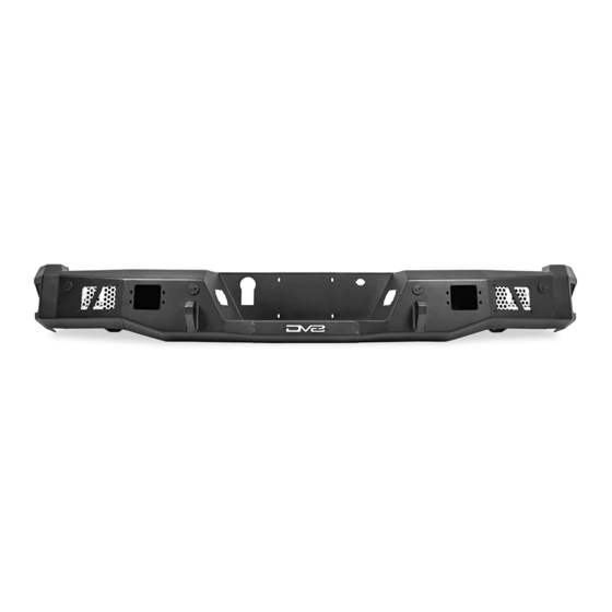
MTO SERIES REAR BUMPER
2021+ F-150
RBFF1-04
TOOLS
REQUIRED
- 10mm, 13mm, 16mm Socket
- 17mm Wrench
- 4mm Allen Bit
- Trim Clip Tool
- Needle Nose Pliers
- Angle Grinder
- Flathead Screwdriver
- Zip Ties (Optional)
WARNINGS/CAUTIONS BEFORE STARTING INSTALLATION
Before you install this kit —
instructions, warnings, cautions, and notes contained in
this installation instruction guide. Consult your vehicle
owner's manual for proper disconnection of electrical and
lifting of vehicle if required for installation of this product.
This install may require some technical skills and
knowledge of basic mechanical work. If you do not feel that
you are capable of performing this install please take this
product to a trained professional.
After reading this guide please contact us with any
questions or concerns before installing product.
Customer Service: 855-680-9595
DV8 Offroad is not responsible for any bodily injury or harm to you
or your vehicle as a result of an improper install.
6400 SYCAMORE CANYON BLVD.
RIVERSIDE, CALIFORNIA 92507
855-680-9595
WWW.DV8OFFROAD.COM
SKILL
LEVEL
- Novice/Intermediate
- 2 to 3 persons
Little skill level required, however,
additional assistance will be required
for installation and removal of bum-
pers.
Read and understand all
PRODUCT
INSTALLATION
TIME
- 3 Hours
Time to install this should only
take about three hours.
Proper installation of this kit required knowledge of the factory
recommended procedures for removal and installation of original
equipment components. We recommend that the factory shop manual
and any special tools needed to service your vehicle be on hand during
the installation. Installation of this kit without proper knowledge of the
factory recommended procedures may affect the performance of these
components and the safety of the vehicle
• Always wear eye protection when operating power tools
Inspect all contents of this package to make sure product is not damaged
and all installation hardware has been included. If parts are missing from
kit, please be prepared to provide the following information
1. Name of purchase location
2. Bar Code on side of box
3. Date above bar code
4. Date inside box cover
NEED HELP?
MANUAL
REQUIRED
855-680-9595
Advertisement

Related Manuals for DVB Off-ROAD MTO Series


Summary of Contents for DVB Off-ROAD MTO Series
- Page 1 6400 SYCAMORE CANYON BLVD. PRODUCT INSTALLATION MANUAL RIVERSIDE, CALIFORNIA 92507 855-680-9595 WWW.DV8OFFROAD.COM MTO SERIES REAR BUMPER 2021+ F-150 RBFF1-04 TOOLS REQUIRED SKILL LEVEL TIME REQUIRED - 10mm, 13mm, 16mm Socket - Novice/Intermediate - 3 Hours - 17mm Wrench - 2 to 3 persons Time to install this should only - 4mm Allen Bit take about three hours.
- Page 2 INSTALLATION MANUAL Begin by unpacking all items and inspecting for missing pieces or damage. If you have any concens, please contact the company the product was purhcased from. HARDWARE INCLUDED (6) M10x40 Hex (4) M6 Nylon Lock Nuts (12) M10 Flat Washers (6) M10 Nylon Lock Nuts (4) M6x20 Allen (8) M6 Flat Washers...
- Page 3 INSTALLATION MANUAL STEP 2 | Use a trim clip tool to remove the clips securing the ground wire to the frame rail. One clip is located next to where the ground was secured, and the other is on top of the frame rail above the spare tire. STEP 3 | Remove the trailer wiring plug from the bumper using a trim clip...
- Page 4 INSTALLATION MANUAL STEP 4 | Remove the license plate lights using a trim clip tool to press on the two release tabs. The release tabs are located on the side and bottom of the lights. Remove the wiring harness from the lights by pressing down the release tab and pulling away.
- Page 5 INSTALLATION MANUAL STEP 6 | Remove the sensors from their bezels on the bumper by gently spreading the tabs on the sensor bezel to release them. STEP 7 | Use needle nose pliers to squeeze the release tabs and push up from underneath the bumper, and have a friend pull up on the trim from the top of the bumper.
- Page 6 INSTALLATION MANUAL STEP 9 | Use a 10mm socket to remove the bolts located on both sides of the hitch step. STEP 10 | Remove the eight bolts securing the bumper to the vehicle using a 13mm socket. -Four are located on the outside edge of both frame rails.
- Page 7 INSTALLATION MANUAL STEP 12 | Remove the wiring harness from the vehicle by gently feeding the wires through, or sliding it over, the bumper support bracket and set it off to the side. STEP 13 | Remove the lock for the spare tire by rotating the lock and pulling out.
- Page 8 INSTALLATION MANUAL STEP 15 | Install the license plate lights by pressing them until they “clip” into place. STEP 16 | Install the trailer plug on the DV8 bumper by pressing it until it “clips” into place. STEP 17 | Install the license plate using the provided M6 hardware with a 4mm allen bit and 10mm socket.
- Page 9 INSTALLATION MANUAL STEP 18 | If you are running flush mount pod lights, install them at this time using the hardware provided with the light. Note: We are using 3” elite series flush mount pod lights for our install. Part Number: BE3FMW40W STEP 19 | Factory sensor bezels must be trimmed for installation on the...
- Page 10 INSTALLATION MANUAL STEP 20 | Install the sensor bezels into the DV8 bumper in the locations they were removed from the factory bumper. Tip: Reference the painters tape from step 12, or the bezels to determine their install location. Example: “ROR” stands for “Rear Outer Right”. STEP 21 | Connect the license plate light wiring harness to the license plate...
- Page 11 INSTALLATION MANUAL STEP 23 | Install sensors into their bezels by gently pressing them until they “clip” into place. Note: If the wires are not long enough to install in the same direciton as the picture, you can flip them. Sensors can be installed into the bezels in either direction.
- Page 12 INSTALLATION MANUAL Install the bumper to the vehicle and loosely secure using the provided M10 hardware with a 16mm socket and 17mm wrench. There is room to slip a wrench in from the bottom of the bumper. Make sure the wiring is not pinched between the bumper and vehicle during install.
- Page 13 INSTALLATION MANUAL STEP 27 | Use a 10mm socket to secure the ground wire to the driver side frame rail. Secure ground wiring using the factory wire clips from step 2. Tip: Use zip ties to secure any loose sections of wiring for a cleaner install.
Need help?
Do you have a question about the Off-ROAD MTO Series and is the answer not in the manual?
Questions and answers