Table of Contents
Advertisement
Quick Links
OPERATING INSTRUCTIONS FOR
Model 7500ZB
NDIR Infrared Gas Analyzer
P/N M7500ZB
9/09/2015
DANGER
Toxic gases and or flammable liquids may be present in this monitoring system.
Personal protective equipment may be required when servicing this instrument.
Hazardous voltages exist on certain components internally which may persist
for a time even after the power is turned off and disconnected.
Only authorized personnel should conduct maintenance and/or servicing.
Before conducting any maintenance or servicing, consult with authorized
supervisor/manager.
Teledyne Analytical Instruments
Advertisement
Table of Contents

Related Manuals for Teledyne Analytical Instruments 7500ZB


Summary of Contents for Teledyne Analytical Instruments 7500ZB
- Page 1 OPERATING INSTRUCTIONS FOR Model 7500ZB NDIR Infrared Gas Analyzer P/N M7500ZB 9/09/2015 DANGER Toxic gases and or flammable liquids may be present in this monitoring system. Personal protective equipment may be required when servicing this instrument. Hazardous voltages exist on certain components internally which may persist for a time even after the power is turned off and disconnected.
- Page 2 Teledyne Analytical Instruments, the manufacturer of this instrument, cannot accept responsibility for conditions beyond its knowledge and control. No statement expressed or implied by this document or any information disseminated by the manufacturer or its agents, is to be construed as a warranty of adequate safety control under the user’s process...
- Page 3 Consult the factory for additional information for gas analysis not specified at the time of purchase. Instrument Serial Number: _______________________ Measurable Built-In External Species: Fuel Cell Channel #: ZrO2 Range 1: Range 2: Span Gas 1: Span Gas 2: Zero Gas: Background: Teledyne Analytical Instruments...
- Page 4 Model 7500ZB Teledyne Analytical Instruments...
-
Page 5: Safety Messages
NOTE: Additional information and comments regarding a specific component or procedure are highlighted in the form Symbol of a note. CAUTION: THE ANALYZER SHOULD ONLY BE USED FOR THE PURPOSE AND IN THE MANNER DESCRIBED IN THIS MANUAL. Teledyne Analytical Instruments... - Page 6 Model 7500ZB IF YOU USE THE ANALYZER IN A MANNER OTHER THAN THAT FOR WHICH IT WAS INTENDED, UNPREDICTABLE BEHAVIOR COULD RESULT POSSIBLY ACCOMPANIED WITH HAZARDOUS CONSEQUENCES. This manual provides information designed to guide you through the installation, calibration operation and maintenance of your new analyzer.
-
Page 7: Additional Caution On Safety
Be sure to wear protective gloves when lifting the analyzer. Lifting it with bare hands may result in injury. Be sure to fix the cover before transporting the analyzer. Transportation in unstable state may result in injury. Teledyne Analytical Instruments... - Page 8 Model 7500ZB The gas analyzer is heavy. To transport the analyzer, please use a hand cart or equivalent. Avoid carrying analyzer by hand as much as possible. Doing so may cause injury. Take care not to let cable chips and other foreign objects enter the unit during installation work.
- Page 9 DANGER analyzer open for maintenance and check, be sure to purge completely not only within the analyzer but also measuring gas lines using nitrogen or air. Otherwise, poisoning, fire, or explosion may result due to gas leakage. Teledyne Analytical Instruments...
- Page 10 Model 7500ZB Be sure to observe the following to perform work CAUTION safely, avoiding electric shock or injury. Remove the watch and other metallic objects before work. Do not touch the instrument with wet hands. If the fuse is blown, eliminate the cause and replace it with the one of the same capacity and type.
-
Page 11: Table Of Contents
3.4.3 Preparation of Standard Gas 3.4.4 Internal Purging of the Instrument Housing 3.4.5 Pressure at Sample Outlet 3.4.6 Example Configuration of Sample System 3.5 Electrical Connections Operation ..................25 4.1 Preparation for Operation 4.2 Warm-up Operation and Normal Operation Teledyne Analytical Instruments... - Page 12 Model 7500ZB Display And Operation Panels ........... 27 5.1 Front Panel Description 5.2 Overview of Display and Operation Panels 5.3 Outline of Display Screen 5.4 Basic Operation Settings and Calibration ............. 35 6.1 Range 6.1.1 Setting the Range Mode 6.1.2 Manual Range Mode 6.1.3 Range Identification Contacts...
- Page 13 8.1 Troubleshooting 8.2 Error Log File 9. Specifications ................89 9.1 General Specifications 9.1.1 Standard Specifications 9.1.2 Standard Functions 9.1.3 Optional Functions 9.1.4 Performance 9.1.5 EC Directive Compliance 9.1.6 Requirements for Sample Gas 9.1.7 Installation Requirements Teledyne Analytical Instruments xiii...
- Page 14 Model 7500ZB 9.2 Table 1 Measurable Component and Range 9.3 Code Symbols 9.4 Outline Diagram Teledyne Analytical Instruments...
-
Page 15: List Of Figures
List of Figures Figure 1-1: Model 7500ZB............... 1 Figure 2-1: Model 7500ZB Front Panel ........... 4 Figure 2-2: Electrical Feedthroughs on the Model 7500ZB ..... 5 Figure 2-3: Terminal Connections for Model 7500ZB...... 5 Figure 3-1: Analyzer Dimensions ............ 9 Figure 3-2: Gas Connections............ -
Page 16: List Of Tables
Model 7500ZB List of Tables Table 7.1 Maintenance and Check Table........76 Table 8-1: Error Messages............85 Teledyne Analytical Instruments... - Page 17 Since the use of this instrument is beyond the control of Teledyne, no responsibility by Teledyne, its affiliates, and agents for damage or injury from misuse or neglect of this equipment is implied or assumed. Teledyne Analytical Instruments xvii...
-
Page 19: Introduction
NDIR Gas Analyzer Introduction Introduction 1.1 Overview The Model 7500ZB is a wall mounting Infrared Gas Analyzer designed to measure the concentration of up to four different species that may include NO, SO , CO , CO and CH in a sample gas. Analysis is... -
Page 20: Typical Applications
Introduction Model 7500ZB 1.2 Typical Applications The Model 7500ZB is a microprocessor based analyzer with a large LCD display, superior accuracy and a multitude of functions suitable for a variety of applications including: • Combustible gas emissions from boilers or incinerators •... -
Page 21: Items Included With The Analyzer
Analog Output Connector (1) 25 pin D-sub male M2.6x4 mm Instruction Manual External Input Connector (1) (External O2/External Zirconia Sensor as specified) Digital Input Connector (3 max with the no. of DIO when digital I/O function is specified). Teledyne Analytical Instruments... -
Page 22: Name And Description Of Analyzer
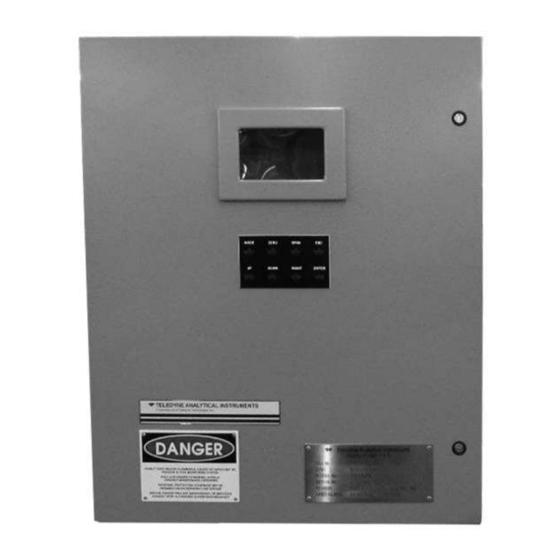
It allows for operation without having to open the door. A view window allows visual access to the instrument display. Figure 2-1: Model 7500ZB Front Panel Teledyne Analytical Instruments... -
Page 23: Figure 2-2: Electrical Feedthroughs On The Model 7500Zb
2-2 with connections made to the three internal terminal blocks as shown in Figure 2-3. Figure 2-2: Electrical Feedthroughs on the Model 7500ZB Figure 2-3: Terminal Connections for Model 7500ZB Teledyne Analytical Instruments... - Page 24 Items Included with Analyzer Model 7500ZB [Blank page] Teledyne Analytical Instruments...
-
Page 25: Installation
NDIR Gas Analyzer Instalation Installation Installation of the Model 7500ZB NDIR Analyzer includes: Unpacking Mounting Gas connections Electrical connections Calibration DANGER: THIS UNIT IS NOT AN EXPLOSION-PROOF INSTRUMENT. DO NOT USE IT IN A PLACE WITH EXPLOSIVE GASES TO PREVENT EXPLOSION, FIRE OR OTHER SERIOUS ACCIDENTS. -
Page 26: Installation Conditions
3.2.1 Installation of Analyzer Enclosure Installation methods for the analyzer main unit is shown below. The Model 7500ZB is designed to be wall mounted in a general purpose environment. Figure 3-1 indicates the pertinent dimensions in inches and [mm] for installation. See also the Outline Diagram in the Appendix. -
Page 27: Figure 3-1: Analyzer Dimensions
200V AC), and temperature fluctuation during operation is minimum. • Where vibration is unavoidable, protect the analyzer from vibrating. If necessary, install rubber or other vibration absorbing material around the case to isolate any vibration from the support structure. Teledyne Analytical Instruments... -
Page 28: Piping
Installation Model 7500ZB 3.3 Piping • Piping should be connected to the 1/4” tube fittings on the right side panel panel of the enclosure. • Use a corrosion resistant tubing comprised of Teflon, stainless steel or polyethylene to connect the analyzer to a sampling system. - Page 29 SECURE A GAS TIGHT SEAL. EACH FITTING MUST BE LEAK CHECKED WHENEVER A CONNECTION HAS BEEN OPENED OR DISTURBED. The internal piping diagram for the Model 7500ZB is shown in Figure 3-3. Depending on the application, the unit may have one or two optical benches installed.
-
Page 30: Sampling
Installation Model 7500ZB Figure 3-3: Internal Piping for the Model 7500ZB 3.4 Sampling 3.4.1 Sample Gas Conditioning 1. Dust from the sampling gas should be completely removed using a filter. For the final stage filter, use a filter that removes dust particles down to 0.3µm. -
Page 31: Sample Gas Flow
Gas with conc. of gas at 1 to 2% Span gas for O 90 to 100% on measurement the measuring range or atmospheric air (21% O — gas of 95 to 95.5 vol% for reverse range O measurement.) Teledyne Analytical Instruments... -
Page 32: Internal Purging Of The Instrument Housing
Installation Model 7500ZB 3.4.4 Internal Purging of the Instrument Housing The internal housing does need not be purged except under the following conditions: 1. A combustible gas component is contained in the sample gas. 2. Corrosive gas is contained in the atmospheric air at the installation site. -
Page 33: Electrical Connections
• Be sure to connect a power supply of correct rating. There are five terminal blocks (TB1-TB5) mounted inside the enclosure for making AC power and user connections. Refer to the diagram below. Teledyne Analytical Instruments... - Page 34 Installation Model 7500ZB (1) Power Supply (TB3) Connect the power supply to the power terminal block TB3, and connect the ground wire to the grounding terminal. Be sure to provide a protective earth connection. Use solderless terminals for connection to the terminals (power and earth).
- Page 35 4 to 20 mA DC or 0 to 1 V DC (option). Minus lines for the insulation and signal are common from the ground and internal circuit. Allowable load : 4 to 20 mA DC, 550Ω or less 0 to 1 V DC, 100kΩ or more Teledyne Analytical Instruments...
- Page 36 Installation Model 7500ZB The analog output signals of the instrument are not isolated individually. It is recommended to isolate the signals individually to eliminate the interference from unwanted signals or other external interference, especially if the cable exceeds 30 meters or leads to outdoors.
- Page 37 The zirconia O sensor should be installed at a location that is as close to the analyzer as possible. The figure below shows how to connect the O signal to the dedicated connector (accessory). Teledyne Analytical Instruments...
- Page 38 Installation Model 7500ZB (4) Contact input/output (DIO): digital input/output connector (DIO 1 to 3) Contact input signal : Voltage is applied from the external 12 to 24 V DC, max 15mA. Photo-coupler isolation (from each DI and ground) Contact capacity :...
- Page 39 NDIR Gas Analyzer Instalation Teledyne Analytical Instruments...
- Page 40 Installation Model 7500ZB • Isolated output (from each DO and ground) To avoid external interference, the wiring from the analog output signal, O sensor input and contact input should be run separately from that of power supply and contact output.
- Page 41 NDIR Gas Analyzer Instalation 2. Automatic calibration: (See also Section 6.4: Automatic Calibration Settings) Teledyne Analytical Instruments...
- Page 42 Installation Model 7500ZB Calibration status signals are available at TB2. Teledyne Analytical Instruments...
-
Page 43: Operation
4. After the warm-up period, perform the zero/span calibration as described in Section 6.8 Calibration. 5. After calibrating the analyzer, introduce sample gas into the analyzer and allow the lines to purge before accepting the measurement value. Teledyne Analytical Instruments... - Page 44 Installation Model 7500ZB [Blank page] Teledyne Analytical Instruments...
-
Page 45: Display And Operation Panels
Display and Operation Panels Display And Operation Panels This section describes the display unit and operation panel on the Model 7500ZB as well as the various functions available to the user. 5.1 Front Panel Description Display unit: The measurement screen and the setting items are displayed. -
Page 46: Overview Of Display And Operation Panels
Display and Operation Panels Model 7500ZB 5.2 Overview of Display and Operation Panels Teledyne Analytical Instruments... -
Page 47: Outline Of Display Screen
• The concentration display of Ch (component) where sampling components such as “CO2”, “CO” and “O2” are displayed in the component display, are the current concentration values of the measured components contained in sample gas under test. Teledyne Analytical Instruments... - Page 48 Display and Operation Panels Model 7500ZB • corrected concentration values: • Ch components in which “cv**” is displayed as “cv CO” in the display are calculated values derived from the following equation. Refer to Section 6.7 Maintenance Mode - Other Parameter.
- Page 49 In the setting item and selection item display area, items or values to be set are displayed, as required. To navigate through the fields, move the cursor to any item using the UP, DOWN and SIDE keys. Teledyne Analytical Instruments...
- Page 50 Display and Operation Panels Model 7500ZB (3) Contents of Measured Channel (Ch) The following table gives measurement channels and their contents according to the symbols. • Teledyne Analytical Instruments...
-
Page 51: Basic Operation
• Select the function by pressing the ENT (ENTER) key. The screen display will change to that of the selected function. • Each function is described in Chapter 6. Settings and Calibration. Teledyne Analytical Instruments... - Page 52 Display and Operation Panels Model 7500ZB BLANK PAGE Teledyne Analytical Instruments...
-
Page 53: Settings And Calibration
5. The selected range switch mode will be highlighted. Press the UP or DOWN key to select the desired mode. 6. Then press the ENT key to confirm the selection. 7. If “MR” is selected, the cursor moves to “Range Switch.” Teledyne Analytical Instruments... -
Page 54: Manual Range Mode
Settings and Calibration Model 7500ZB 6.1.2 Manual Range Mode The analysis range for the measured component can be switched manually as follows: 1. (1) Select “MR” as range switch mode, and then press the ENT key. 2. Using the UP/DOWN keys, move the cursor to the desired range selection. -
Page 55: Calibration Setting
Span) by pressing the UP, DOWN or SIDE (>) key. The SIDE key only functions within the selected channel. Press the ENT key when the cursor is in the desired field. The first digit of the parameter is highlighted. Teledyne Analytical Instruments... -
Page 56: Manual Zero Calibration
Settings and Calibration Model 7500ZB 4. Enter calibration gas concentration for zero and span. Use the UP or DOWN key to increment or decrement the displayed value one digit at a time. When the correct number is displayed for that digit, use the SIDE key to move to the next digit and repeat the increment/decrement process with the UP/DOWN keys. - Page 57 Select the Ch (component) on the manual zero calibration screen and then perform the zero calibration. Setting “at once” In a manual zero calibration, Ch (components) for which “at once” are selected will simultaneously be zero-calibrated. Teledyne Analytical Instruments...
-
Page 58: Setting The Calibration Range
Settings and Calibration Model 7500ZB 6.2.3 Setting the Calibration Range This mode is used to set whether the channels use one or both of the calibration ranges. 1. From the Calibration Parameters screen, select Calibration Range. The following screen appears. - Page 59 Range 2: 0 to 2000 ppm Ch1: Range 1 and Range 2 are calibrated together Ch2: Only the currently displayed range is calibrated Note: When “both” is selected, the same calibration gas concentration must be used for both ranges. Teledyne Analytical Instruments...
-
Page 60: Setting The Component/Range For Auto Calibration
Settings and Calibration Model 7500ZB 6.2.4 Setting the Component/Range for Auto Calibration In this section you can select the Ch (component) and the range to calibrate on for those components that have the auto ranging (AR) feature enabled. 1. From the User Mode screen select <... - Page 61 Ch (component) that have “enable” set in the Auto Calibrations Setting screen. Note: ZERO calibrations for components which have been set to “enable” in the Auto Calibration Settings screen (above) are performed in batch irrespective of the description in “6.2.2 Manual Zero Calibration.” Teledyne Analytical Instruments...
-
Page 62: Alarm Setting
Settings and Calibration Model 7500ZB 6.3 Alarm setting 6.3.1 Setting Alarm Parameters The High/Low limit concentration alarms are user adjustable. Five different alarm contact outputs can be used. The setting range is 0- 100% full scale for each range. To change the alarm setting, set the alarm ON/OFF setting to OFF, and then change the value. - Page 63 When an H-limit alarm occurs, the “H-alarm” message displays in the relevant component field. Other alarm displays are: L-alarm for Low-limit alarm, HH- alarm for high limit alarm, HH-alarm for high-high alarm, and LL-alarm for low- low alarm. Teledyne Analytical Instruments...
-
Page 64: Hysteresis Setting
Settings and Calibration Model 7500ZB 6.3.2 Hysteresis Setting The alarm hysteresis can be set or changed to prevent chattering of an alarm output about its alarm set point. To set or change the alarm hysteresis: 1. Navigate to the “Alarm Setting” screen and then move the cursor to “Hysteresis”... -
Page 65: Peak Alarm Setting
(closed). Hysteresis : To prevent possible chattering when the measuring value may exceed the set peak concentration by only 1 time, the peak count has an allowance in the hysteresis width. Teledyne Analytical Instruments... - Page 66 Settings and Calibration Model 7500ZB Setting Range Alarm value: 10-1000 ppm → 5 ppm step (initial value: 500 ppm) Alarm count: 1- 99 times/hr → (initial value: 5 times) Hysteresis : 0-20 % FS → (initial value: 0% of full scale) [% FS] represents the percentage with the CO range regarded as 100%.
-
Page 67: Setting Up The Auto Calibration
ENT key to save them. Subsequent auto calibrations will use the saved settings. Description of Auto Cal Settings • Start Time : Setting for the first calibration event (day of the week, hour, minute) • Cycle : The period between the Teledyne Analytical Instruments... - Page 68 Settings and Calibration Model 7500ZB start time of one calibration and the next (unit: hour/day) • Flow Time : The time required for purging with calibration gas. Time required for replacement of sample gas after the calibration is completed (Set by calibration gas. See the next page.) ON/OFF: Turns the auto calibration feature ON or OFF.
- Page 69 CH 4 Span 300 sec CH 5 Span 300 sec Ex. Time 300 sec ON/OFF Thus, with the above settings: Setting Range: Cycle: 1-99 hours or 1-40 days (default value—7days) Flow Time: 60-90 sec (default value—300 sec) Teledyne Analytical Instruments...
-
Page 70: Forced Run/Stop Of Auto Calibration
Settings and Calibration Model 7500ZB Caution: When an auto calibration starts, the measurement screen appears automatically. Any operation other than “Stop Auto Calibration” (see Item 6.4.2) is not permitted during auto calibration. “Stop Auto Calibration” cannot be performed with the key lock to ON. -
Page 71: Forced Stop Of Auto Calibration
(see Section 6.2.4): • Zero calibration A message, “Zero cal.” blinks at Ch1 and Ch2. • Ch1 span calibration A message, “Span cal.” blinks at Ch1. • Ch2 span calibration A message, “Span cal.” blinks at Ch2. Teledyne Analytical Instruments... - Page 72 Settings and Calibration Model 7500ZB Caution: During an auto calibration, all key operations are not permitted other than key lock ON/OFF and “Auto Calibration Stop.” When the key lock is ON, the “Auto Calibration Stop” is locked out as well.
-
Page 73: Setting Auto Zero Calibration
Description of Auto Zero Settings • Start Time : Setting for the first calibration event (day of the week, hour, minute) • Cycle : The period between the start time of one calibration and the next (unit: hour/day) Teledyne Analytical Instruments... - Page 74 Settings and Calibration Model 7500ZB • Flow Time: The time required for purging with calibration gas. Time required for replacement of sample gas after the calibration is completed (Set by calibration gas. See the next page.) • ON/OFF: Turns the auto calibration feature ON or OFF.
-
Page 75: Forced Run/Stop Of Auto Zero Calibration
A remote start input will begin a calibration event regardless of whether the auto zero calibration is set to ON or OFF. 6.5.2 Forced Run/Stop of Auto Zero Calibration Auto zero calibration can be performed just once, or auto zero calibration can be forcibly stopped during calibration. Teledyne Analytical Instruments... -
Page 76: Execution Of Auto Zero Calibration (Only Once)
Settings and Calibration Model 7500ZB 6.5.2.1 E XECUTION OF AUTO ZERO CALIBRATION ONLY ONCE 1. In the “Setting of Auto Zero Calibration” screen that appears, point the cursor to “Run” by pressing the UP or DOWN key. Then press ENT. - Page 77 ON/OFF and “Auto Zero Calibration Stop.” When the key lock is set at ON, even the “Auto Zero Calibration Stop” cannot be used. To forcibly stop “auto zero calibration”, set the key lock to OFF and then execute “Auto Zero Calibration Stop.” Teledyne Analytical Instruments...
-
Page 78: Parameter Setting
Settings and Calibration Model 7500ZB 6.6 Parameter Setting From the Parameter Setting screen you can set or adjust various parameters of the instrument such as time, key lock, etc. Settable items are as follows: Description of setting items • Current Time : Current year, month, date, day of the week, hour, and minute setting. - Page 79 (see Section 6.4, Setting of Auto Calibration). However, an output signal can be held via an external input regardless of the Hold ON/OFF setting. Teledyne Analytical Instruments...
- Page 80 Settings and Calibration Model 7500ZB Manual Calibration Auto Calibration Remote Input Screen Display During Holding A “Hold ON” message will blink on the measuring screen during a hold period. Teledyne Analytical Instruments...
- Page 81 (1). Pressing the ENT key while “Setting” is selected will bring up the parameter hold screen where an arbitrary hold value can be set. Teledyne Analytical Instruments...
- Page 82 Settings and Calibration Model 7500ZB 4. On the parameter hold screen that appears, move the cursor to the Ch (component) you want to hold using the UP or DOWN key and then press ENT. 5. A highlighted value indicates that it can be changed.
- Page 83 (1-minute step) or 1 to 4 hours (1-hour step). Changing the setting also resets the averaging of O correction and O average value. (Pressing the ENT key resets averaging only for the components whose setting were changed.) Teledyne Analytical Instruments...
- Page 84 Settings and Calibration Model 7500ZB Average Value Reset This mode is used to clear all average values, i.e. O correction average and O average, and restarts averaging. All average values are reset simultaneously. The indication value and output value is 0 ppm, vol% or so at the time of the reset input (based on average period settings).
- Page 85 The next section describes in detail the functions available in maintenance mode. The default password is set at the factory to “0000.” You can enter the maintenance mode with this value before changing the password in maintenance mode to one of your choosing. Teledyne Analytical Instruments...
-
Page 86: Maintenance Mode
3. Press the ESC key to return to the Maintenance Mode item selection screen from each screen. 6.7.1 Sensor Input Value screen There are 5 possible inputs on the Model 7500ZB: 1. Input 1 to 4 : NDIR sensor digital value 2. Input 5 : O2 sensor digital value 6.7.2 Error Log screen... -
Page 87: Calibration Log Screen
Z1 : Zero calibration (Z) of Range 1 S1 : Span calibration (S) of Range 1 Cnt : Value of measuring detector at the time of calibration Con : Concentration value displayed before calibration YDMH: Time of calibration event Teledyne Analytical Instruments... -
Page 88: Output Adjustment Screen
Settings and Calibration Model 7500ZB 6.7.4 Output Adjustment Screen The Analog Output Adjustment screen allows the user to adjust the 0-1 V and 4-20 mA output signal. Connect a digital multi meter to the specific output terminal requiring adjustment and adjust the value so that 4 mA or 0 V is output at zero concentration and 20mA or 1V is output at full scale or span. -
Page 89: Other Parameter
It is settable in the range from 01 to 20%. * Refer to the O2 correction concentration value in “5.3 Outline of display screen” for oxygen correction calculation procedure. Teledyne Analytical Instruments... - Page 90 Settings and Calibration Model 7500ZB Station No. This function allows the user to set the station No. for MODBUS communication. It is settable in the range from 00 to 32. Range Setting This function brings up a screen where the user can set the range for which concentration measurements are made.
-
Page 91: Calibration
“Setting of Auto Calibration Component/Range” (6.2.4), and calibration is carried out on that range. To close the Zero Calibration screen or to abort the entry midway, press the ESC key. The previous screen will return. Teledyne Analytical Instruments... -
Page 92: Span Calibration
Settings and Calibration Model 7500ZB 6.8.2 Span Calibration The Model 7500ZB requires periodic span calibration at or near the full scale value on the range of interest. It requires a prepared standard gas containing a known concentration of the measured species. -
Page 93: Maintenance
Flow rate check 1. Sample and purge gas flow rates are as follows: Sample gas flow : 0.5L/min ± 0.2L/min Purge gas flow : About 1L/min 2. Instrument checks and maintenance should be carried out every day, as required. Teledyne Analytical Instruments... -
Page 94: Daily Check And Maintenance Procedures
Maintenance Model 7500ZB 7.2 Daily Check And Maintenance Procedures Table 7.1 Maintenance and Check Table 7.3 Long Term Maintenance Create a long-term maintenance component procurement plan based on the “Gas analyzer annual inspection plan” indicated below. Gas Analyzer Annual Inspection Plan The recommended replacement period of components varies depending on the installation conditions. - Page 95 , 0 to 2000 ppm CO, 5% to 15% CO , 0% to 21%O , 0 to 100 ppm HCl, residue N Please consult TAI Customer Service regarding gas analyzer maintenance service requirements. Annual Inspection Plan Sheet Teledyne Analytical Instruments...
-
Page 96: Cleaning The Sample Cell
7.4.1 Sample Cell Disassembly There are two kinds of sampling cells used in the Model 7500ZB: block cells (cell length: 4 mm, 8 mm, 16 mm, 32 mm) and pipe cells (cell length: 64 mm, 125 mm, 200 mm and 250 mm). -
Page 97: Block Cell Removal (See Fig. 7-2)
The block cell can be removed together with the detector. 7. To remove the block cell, unscrew the two screws (No. 6) holding the block cell to the detector. The infrared transmission Teledyne Analytical Instruments... - Page 98 Maintenance Model 7500ZB window (No. 8) is just sandwiched (not fixed) between the detector and block cell. Keep the detector facing up, when removing this window. 8. For assembly, reverse the disassembly procedures. Note: The O-ring (No. 9) is placed between the window holder and block cell.
-
Page 99: Figure 7-2: Measuring Unit Configuration (Block Cell)
NDIR Gas Analyzer Maintenance Figure 7-2: Measuring Unit Configuration (Block Cell) Teledyne Analytical Instruments... -
Page 100: Removing The Measuring Unit
Maintenance Model 7500ZB 7.4.1.3 R EMOVING THE EASURING Refer to Fig. 7-3. For step 1 to 4, see 7.4.1.1, Pipe Cell Removal. 5. Disconnect and remove detector output cables from detector output circuit board (No.12). Applying identification mark on top of removed cable connector will ensure proper pin assignment later. - Page 101 NDIR Gas Analyzer Maintenance Figure 7-3: Measuring Unit with 2-Component Block and Pipe Cell Teledyne Analytical Instruments...
-
Page 102: Fuse Replacement
Maintenance Model 7500ZB 7.5 Fuse Replacement Turn “OFF” the main power supply switch to the analyzer. Rotate the fuse holder cap (shown in the figure above) counterclockwise and pull it out. The cap (fuse holder) will contain the fuse. Remove the blown fuse from the holder and replace it with a new one (250VAC/2A, Slo-Blo). -
Page 103: Error Messages
Table 8-1: Error Messages When errors No. 1 to No. 3 and No. 10 occur, analyzing block error contact output closes. When errors No. 4 to No. 9 occur, the calibration error contact output closes. Teledyne Analytical Instruments... -
Page 104: Troubleshooting
Error Messages Model 7500ZB 8.1 Troubleshooting When error No. 1 occurs, remove the top cover of the analyzer and check the LED on the light source PCB. If the LED is off, then the error is caused by a light source disconnection. -
Page 105: Error Log File
When more than one error occurs, use the SIDE key to move to the next error display. For errors 5 and 7: 8.2 Error Log File When an error occurs, the history is saved in an error log file. The error log file is accessible in the maintenance mode. Teledyne Analytical Instruments... - Page 106 Error Messages Model 7500ZB Error Log Screen * Up to 14 errors can be saved in the error history; the oldest error will be deleted one by one every time a new error occurs. * If the power supply is turned OFF, the contents in the error log file will not be lost or damaged.
-
Page 107: Specifications
0-200 ppm 0-5000ppm 0-200 ppm 0-10 vol.% 0-100 ppm 0-100 vol.% 0-200 ppm 0-100 vol.% 0-500 ppm 0-100 vol.% 0-10 vol.% 0-25 vol.% (built in) Fuel Cell 0-5 vol.% 0-100 vol.% (built in) None 100-95 vol.% Paramag. Teledyne Analytical Instruments... - Page 108 Specifications Model 7500ZB 0-5 vol.% 0-25 vol.% External Zirconia Max. 5 components measurement including O For reverse range O measurement, IR gas measurement is not available (single range only). Measuring range ratio max. 1:10 (except User adjustable ranges between the specified minimum and maximum range.
- Page 109 Digital Input: (option) Voltage contact (supply 12-24VDC (15mA Max.)) Max. 9 inputs Remote range change over, auto calibration remote start, remote hold, average value reset, Isolated from the internal circuit with photocoupler. Teledyne Analytical Instruments...
- Page 110 Specifications Model 7500ZB Voltage rating: 100V to 240V AC Power Supply: Allowable range: 85V to 264V AC Frequency: 50Hz/60Hz Power consumption: 100VA max. Operating Conditions: Ambient temperature: -5˚C to 45˚C (40˚C max. when 2 optical system at 200V AC power...
-
Page 111: Standard Functions
* The switch range values are settable between the first range and second range values (low/high range values). Teledyne Analytical Instruments... -
Page 112: Optional Functions
Specifications Model 7500ZB 9.1.3 Optional Functions Remote Output Holding: Output signal is held at the last value or preset value by a voltage input to the remote output holding input terminals. Holding is maintained while the voltage is input to the terminals. Indication of instantaneous values are not held. - Page 113 Contacts turn on at occurrence of manual or auto calibration errors from 4-9. Auto Cal Status Contact Outputs: Contacts turn on during auto calibration. O2 Correction: Correction of measured NO, SO and CO gas concentrations into values at reference concentration Teledyne Analytical Instruments...
- Page 114 Specifications Model 7500ZB Correction formula: C : Sample gas concentration after O correction. Cs : Measured concentration of sample gas. Os : Measured O concentration (Limit setting: 1 to 20% O On : Reference O concentration (value...
- Page 115 (for use, exhaust port of analyzer must be at atmospheric pressure. After atmospheric pressure correction: Zero point: Not affected. Span point: Change is 0.5% measured value or less relative to a 1% change in atmospheric pressure. Correction range: 700hPa-1050hPa Teledyne Analytical Instruments...
-
Page 116: Performance
Specifications Model 7500ZB 9.1.4 Performance Repeatability: ±0.5% of full scale Linearity: 1% of full scale prior to atmospheric pressure correction (option) Zero drift: ±2% of full scale/week. For auto zero calibration use 500ppm or lower range. Span drift: ±2% of full scale/week Response time (for 90% FS response): 1 to 15 sec electrical response. -
Page 117: Requirements For Sample Gas
1) Infrared-ray measurable component, standard O Zero gas: Dry N Span gas ; Each sample gas having concentration 90 to 100% of its measuring range recommended). For external zirconia O sensor use the same calibration gas line: Teledyne Analytical Instruments... -
Page 118: Installation Requirements
Specifications Model 7500ZB Zero gas ; Dry air or atmospheric air (Do not use with CO measurement) Span gas ; For other than O measurement, each sample gas having concentration 90 to 100% of its measuring range. For O measurement, O... - Page 119 More than two components analyzer: 1. The 2nd range in the tables for two and more components is maximum available range. 2. Select the 2nd range less than or equal to the “2nd range (max)”. Teledyne Analytical Instruments...
- Page 120 Specifications Model 7500ZB Teledyne Analytical Instruments...
- Page 121 NDIR Gas Analyzer Specifications Teledyne Analytical Instruments...
- Page 122 Specifications Model 7500ZB Teledyne Analytical Instruments...
- Page 123 NDIR Gas Analyzer Specifications Teledyne Analytical Instruments...
- Page 124 Specifications Model 7500ZB 9.3 Code Symbols Teledyne Analytical Instruments...
- Page 125 When English is specified for display language, “E” should be selected at 20th digit. note6) O2 correction is calculated only for NO, SO2 and CO. note7) When 5 components measurement is specified, “H” must not be specified at 22nd digit. Teledyne Analytical Instruments...
- Page 126 Specifications Model 7500ZB When 4 components measurement is specified and “H” is specified at 22nd digit, 3 points is maximum for alarm output function. note8) When “B” is specified at 24th digit, measuring range should be specified by ppm range code. In this case NO, SO2 and CO measuring range are corresponding range in mg/m3.
- Page 127 NDIR Gas Analyzer Specifications 9.4 Outline Diagram Teledyne Analytical Instruments...
- Page 128 Specifications Model 7500ZB [Blank page] Teledyne Analytical Instruments...
Need help?
Do you have a question about the 7500ZB and is the answer not in the manual?
Questions and answers