Table of Contents
Advertisement
Quick Links
Information contained herein is classified as EAR99 under the U.S.
Export Administration Regulations. Export, reexport or diversion
contrary to U.S. law is prohibited.
OPERATING INSTRUCTIONS FOR
MODEL 3000RS-T
Trace Oxygen Analyzer
Toxic gases and or flammable liquids may be present in this monitoring
system.
Personal protective equipment may be required when servicing this
instrument.
Hazardous voltages exist on certain components internally which may persist
for a time even after the power is turned off and disconnected.
Only authorized personnel should conduct maintenance and/or servicing.
Before conducting any maintenance or servicing, consult with authorized
supervisor/manager.
Teledyne Analytical Instruments
Use and Disclosure of Data
DANGER
P/N M95455
3000RS-T
3/8/2024
Advertisement
Table of Contents

Related Manuals for Teledyne Analytical Instruments 3000RS-T


Summary of Contents for Teledyne Analytical Instruments 3000RS-T
- Page 1 Use and Disclosure of Data Information contained herein is classified as EAR99 under the U.S. Export Administration Regulations. Export, reexport or diversion contrary to U.S. law is prohibited. OPERATING INSTRUCTIONS FOR MODEL 3000RS-T Trace Oxygen Analyzer P/N M95455 3000RS-T 3/8/2024...
- Page 3 Teledyne Analytical Instruments, the manufacturer of this instrument, cannot accept responsibility for conditions beyond its knowledge and control. No statement expressed or implied by this document, or any information disseminated by the manufacturer or its agents, is to be construed as a warranty of adequate safety control under the user’s process...
- Page 4 In addition to all standard features, this model also has separate ports for zero and span gases, and built-in control valves. The internal valves are entirely under the control of the 3000RS-T electronics to automatically switch between gases in synchronization with the analyzer’s operations.
- Page 5 3000RS-T Important Notice Model 3000RS-T complies with all the requirements of the Commonwealth of Europe (CE) for Radio Frequency Interference, Electromagnetic Interference (RFI/EMI), and Low Voltage Directive (LVD). The following International Symbols are used throughout the Instruction Manual. These symbols are visual indicators of important and immediate warnings and when you must exercise CAUTION while operating the instrument.
-
Page 6: Safety Messages
Technician Symbol: All operations marked with this symbol are to be performed by qualified maintenance personnel only. NOTE: Additional information and comments regarding a specific component or procedure are highlighted in the form Symbol of a note. Teledyne Analytical Instruments... - Page 7 Manuals do get lost. Additional manuals can be obtained from Teledyne at the address given in the Appendix. Some of our manuals are available in electronic form via the internet. Please visit our website at: www.teledyne-ai.com. Teledyne Analytical Instruments...
- Page 8 Since the use of this instrument is beyond the control of Teledyne, no responsibility by Teledyne, its affiliates, and agents for damage or injury from misuse or neglect of this equipment is implied or assumed. Teledyne Analytical Instruments...
-
Page 9: Table Of Contents
2.4 Electronics and Signal Processing Installation ................... 17 3.1 Unpacking the Analyzer 3.2 Mounting the Analyzer 3.3 Rear Panel Connections 3.3.1 Gas Connections 3.3.2 Electrical Connections 3.3.2.1 24VDC Input Power 3.3.2.2 50-Pin Equipment Interface Connector 3.3.2.3 RS-232 Port Teledyne Analytical Instruments viii... - Page 10 4.5.8.3 Profibus Task 4.5.9 Analog Output 4.5.9.1 Range Identification 4.5.9.2 Concentration 4.5.10 More Screen 4.5.10.1 Serial Number 4.5.10.2 Negative Number 4.5.10.3 Stream Selection 4.5.10.4 Model Number 4.5.11 Version 4.5.12 System Status 4.5.13 Firmware Upgrade 4.6 The Range Function Teledyne Analytical Instruments...
- Page 11 5.2.4 Installing a New Micro-Fuel Cell 5.3 Fuse Replacement 5.4 System Self Diagnostic Test 5.5 Major Internal Components 5.6 Cleaning 5.7 Troubleshooting Appendix ..................114 A-1 Model 3000RS-T Specifications A-2 Recommended 2-Year Spare Parts List A-3 Drawing List Teledyne Analytical Instruments...
- Page 12 Trace Oxygen Analyzer A.4 Application notes A-5 Material Safety Data Sheet Teledyne Analytical Instruments...
- Page 13 List of Figures Figure 1-1: Model 3000RS-T Front Panel ........3 Figure 1-2: Model 3000RS-T Rear Panel ........5 Figure 2-1: MFC and Cell Block (Front View of 3000RS-T with door open) ..............8 Figure 2-2: Micro-Fuel Cell .............. 9 Figure 2-3: Cross Section of a Micro-Fuel Cell (not to scale) ..
- Page 14 Table 3-2: Alarm Relay Contact Pins ..........23 Table 3-3: Remote Calibration Connections ........24 Table 3-4: Range ID Relay Connections ........26 Table 3-5: Commands via RS-232 Input ........28 Table 5-1: Self Test Failure Codes ..........110 Teledyne Analytical Instruments xiii...
-
Page 16: Introduction
Oxygen Analyzer. It is a versatile microprocessor-based instrument for detecting oxygen at the parts-per-million (ppm) level in a variety of gases. This manual covers the Model 3000RS-T general purpose flush- panel rack-mount units only. These units are for indoor use in a nonhazardous environment. -
Page 17: Model Designations
1.4 Model Designations 3000RS-T: Standard model. 3000RS-T-C: In addition to all standard features, this model also has separate ports for zero and span gases, and built-in control valves. The internal valves are entirely under the control of the 3000RS-T Teledyne Analytical Instruments... -
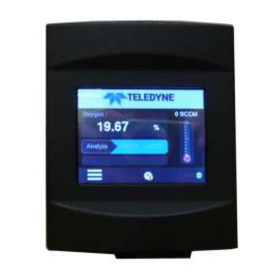
Page 18: Front Panel (Operator Interface)
1.5 Front Panel (Operator Interface) The standard 3000RS-T is housed in a rugged case with a front panel mounted touch screen display that handles all gas controls and displays. See Figure 1-1. The touch screen panel has a touch sensitive button to access various menus and sub menus for setting up and operating the analyzer. -
Page 19: Front Access Door
LAN status icon displays when the LAN connection established. 1.6 Front Access Door For access to the cell holder and the Micro-Fuel Cell, the front panel door is hinged and swings down after pressing the top latch. Teledyne Analytical Instruments... -
Page 20: Rear Panel (Equipment Interface)
The rear panel, shown in Figure 1-2, contains the gas and electrical connectors for external inlets and outlets. The connectors are described briefly here and in detail in the Installation chapter of this manual. Figure 1-2: Model 3000RS-T Rear Panel Teledyne Analytical Instruments... - Page 21 Note: If you require highly accurate Auto-Cal timing, use external Auto-Cal control where possible. The internal clock in the Model 3000RS-T is accurate to 2-3 %. Accordingly, internally scheduled calibrations can vary 2-3 % per day. Teledyne Analytical Instruments...
-
Page 22: Operational Theory
2.2 Micro-Fuel Cell Sensor 2.2.1 Principles of Operation The oxygen sensor used in the Model 3000RS-T Analyzer is a Micro-Fuel Cell designed and manufactured by Analytical Instruments. It is a sealed plastic disposable electrochemical transducer and installs easily from the front door in a compartment with a threaded sample cell holder. -
Page 23: Anatomy Of A Micro-Fuel Cell
Cell Holder Latch Door Figure 2-1: MFC and Cell Block (Front View of 3000RS-T with door open) 2.2.2 Anatomy of a Micro-Fuel Cell The Micro-Fuel Cell is a cylinder only 11/4 inches in diameter and 11/4 inches thick. It is made of an extremely inert plastic, which can be placed confidently in practically any environment or sample stream. -
Page 24: Figure 2-2: Micro-Fuel Cell
At the rear of the cell, just below the anode structure, is a flexible membrane designed to accommodate the internal volume changes that occur throughout the life of the cell. This flexibility assures that the sensing membrane remains in its proper position, keeping the electrical output constant. Teledyne Analytical Instruments... -
Page 25: Electrochemical Reactions
The overall reaction for the fuel cell is the SUM of the half reactions above, or: →2PbO 2Pb + O (These reactions will hold as long as no gaseous components capable of oxidizing lead—such as iodine, bromine, chlorine and fluorine—are present in the sample.) Teledyne Analytical Instruments... -
Page 26: The Effect Of Pressure
(within ± 1 ppm oxygen). In practical application, zeroing may still be used to compensate for the combined zero offsets of the cell and the electronics. (The electronics is zeroed automatically when the instrument power is turned on.) Teledyne Analytical Instruments... -
Page 27: Sample System
Depending on the mode of operation either sample or calibration gas is delivered. The Model 3000RS-T sample system is designed and fabricated to ensure that the oxygen concentration of the gas is not altered as it travels through the sample system. -
Page 28: Figure 2-5: Piping Layout And Flow Diagram For Standard Model
Sample In port by teeing to the port with appropriate valves. The shaded portion of the diagram shows the components added when the –C option is ordered. The valving is installed inside the 3000RS-T-C enclosure and is controlled by the instrument’s internal electronics. -
Page 29: Electronics And Signal Processing
Operational Theory 3000RS-T 2.4 Electronics and Signal Processing The Model 3000RS-T Trace Oxygen Analyzer uses a microcon- troller to operate all signal processing, input/output, and display functions for the analyzer. The signal processing electronics including the microprocessor, analog to digital, and digital to analog converters are located on the motherboard at the bottom of the case. - Page 30 4-20 mA DC and the 0-1 VDC analog concentration signal outputs, and the analog range ID outputs. Signals from the power supply are also monitored, and through the microprocessor, the system failure alarm is activated if a malfunction is detected. Teledyne Analytical Instruments...
-
Page 31: Figure 2-8: Block Diagram Of The Model 3000Rs-T Electronics
Operational Theory 3000RS-T Figure 2-8: Block Diagram of the Model 3000RS-T Electronics Teledyne Analytical Instruments... -
Page 32: Unpacking The Analyzer
Immediately report any damage or shortages to the shipping agent. 3.2 Mounting the Analyzer The Model 3000RS-T is for indoor use in a general-purpose area. It is NOT for hazardous environments of any type. The RS series analyzers are designed to mount in a 3U size 19"... -
Page 33: Rear Panel Connections
Figure 3-1: Front Access Door 3.3 Rear Panel Connections Figure 3-2 shows the Model 3000RS-T rear panel. There are ports for gas, power, and equipment interface. The Zero in and Span in ports are not included on the standard model but are available as options. -
Page 34: Gas Connections
The gas ports are 1/8”. The analyzer does not have flow control, therefore a needle valve or an orifice/restrictor is going to be needed to control the flow into the analyzer. If the 3000RS-T has three inlet ports, for zero, sample, and span, then each port will need its own flow control device. - Page 35 EXHAUST OUT: Exhaust connections must be consistent with the hazard level of the constituent gases. Check Local, State, and Federal laws, and ensure that the exhaust stream vents to an appropriately controlled area if required. Teledyne Analytical Instruments...
-
Page 36: Electrical Connections
The Auto Calibration feature uses electrically operated internal valves for automatic switching between sample and calibration gases. These valves are completely under control of the 3000RS-T Electronics. They can be externally controlled only indirectly through the Remote Cal Inputs, described below. -
Page 37: Figure 3-3: Equipment Interface Connector Pin Arrangement
– Range ID, 4-20 mA, floating + % Range, 4-20 mA, floating – % Range, 4-20 mA, floating + Range ID, 0-1 VDC – Range ID, 0-1 VDC, negative ground + % Range, 0-1 VDC – % Range, 0-1 VDC, negative ground Teledyne Analytical Instruments... -
Page 38: Table 3-2: Alarm Relay Contact Pins
Alarm configuration screen. Further detail can be found in Chapter 4 Section 4-7. Table 3-2: Alarm Relay Contact Pins Contact Threshold Alarm 1, normally closed contact. Threshold Alarm 1, moving contact. Threshold Alarm 1, normally open contact. Teledyne Analytical Instruments... -
Page 39: Table 3-3: Remote Calibration Connections
Cal Contact: This relay contact is closed while analyzer is spanning and/or zeroing. (See Remote Calibration Protocol below.) Table 3-3: Remote Calibration Connections Function + Remote Zero – Remote Zero + Remote Span – Remote Span Cal Contact Cal Contact Teledyne Analytical Instruments... - Page 40 Trace Oxygen Analyzer Installation Remote Calibration Protocol: To properly time the Digital Remote Cal Inputs to the Model 3000RS-T Analyzer, the customer's controller must monitor the Cal Relay Contact. When the contact is OPEN, the analyzer is analyzing, the Remote Cal Inputs are being polled, and a zero or span command can be sent.
-
Page 41: Figure 3-4: Remote Probe Connections
At this printing, this port is not yet functional. It is to be used for future options to the instrument. Pins 13 (+) and 29 (–). Remote Valve Connections: The 3000RS-T is a single-chassis instrument, which has no Remote Valve Unit. Instead, the Remote Valve connections are used as a method for directly controlling external sample/zero/span gas valves. -
Page 42: Port
Which alarms—if any—are disabled (AL–x DISABLED) • Which alarms—if any—are tripped (AL–x ON). Each status output is followed by a carriage return and line feed. Three input functions using RS-232 have been implemented to date. They are described in Table 3-5. Teledyne Analytical Instruments... -
Page 43: Profibus Port
There is a port for Profibus communication. The address is set in the in the System menu through the front panel touchscreen. The master Profibus PLC needs a GSD file to connect to the 3000RS-T. Request the GSD file from customer service at TAI. -
Page 44: Installing The Micro-Fuel Cell
(see section 3.3.1). • Check that inlet sample pressure is within the accepted range (see section 3.3.1). • Power up the system and test it by repeating the Self- Diagnostic Test as described in Chapter 4, Section 4.3.5. Teledyne Analytical Instruments... -
Page 46: Operation
• Set alarm setpoints, and modes of alarm operation (latching, failsafe, etc). Before you configure your 3000RS-T these default values are in effect: Ranges: LO = 100 ppm, MED = 1000 ppm, HI = 10,000 ppm. -
Page 47: Diagnostic Screen
It will update the status [PASS/FAIL] on this screen as it proceeds. The Self-Test routine includes the following processes. - Power supply section testing, - Analog output section testing - Pre-amp testing Teledyne Analytical Instruments... - Page 48 Use the scroll bar to view the additional test results. Screen 1: Using the scroll bar, you can view all the test results. Screen 2: It is possible to skip the self-test at any time by pressing Skip button. Teledyne Analytical Instruments...
-
Page 49: Factory Reset Screen
The Electronics Offset calculation screen will display as follows: The Skip button at the bottom is used to skip the electronics test and proceed to the self-test. If the electronics offset is only partially Teledyne Analytical Instruments... -
Page 50: Main Screen
The bar at the bottom of the screen includes a menu select button, an alarm indicator, and an icon indicating current communication status. This bar will change in appearance depending on the selected function or system notification. Teledyne Analytical Instruments... - Page 51 Operation 3000RS-T Two types of notification bars are used in 3000RS-T user interface (UI) screens: A. Main Menu: This is the notification bar with the menu select button displayed: B. All other screens: All other screens except Diagnostic and Factory reset screens have the Back button available to revert to the previous screen.
-
Page 52: Menu Screen
This screen has the “Back” arrow icon to navigate back to the Main screen. The Menu screen has 6 selection buttons which are, 1. Analyze - Change system to Analyze mode. 2. Span - Start Span calibration. Teledyne Analytical Instruments... -
Page 53: System Screen
Use the scroll bar on the right to view the various system functions. The System screen provides the following functions: 1. Screen 1: Password, Logout, Track/hold, Auto Cal. 2. Screen 2: Self-test, Flow limit, VB Baud rate, Profibus. Teledyne Analytical Instruments... -
Page 54: Password
The display screen text that accompanies each operation is reproduced, at the appropriate point in the procedure. 4.5.1 Password The Password setup function is available from the first System screen. Selecting the password option from the first System screen produces the following display: Teledyne Analytical Instruments... - Page 55 Change: This option can be used to change the existing password of the instrument. When the user presses the change option, the screen will change to Enter Password screen. Here the user must verify the existing password to get access to change the password. Teledyne Analytical Instruments...
- Page 56 : upper case letters display button. : lower case letters display button. Pressing any of the above icons will display the type and format of the characters available: Qwerty pad: Lower case letters (select if another format button is currently enacted): Teledyne Analytical Instruments...
- Page 57 Operation 3000RS-T Qwerty pad: Upper case letters: (Select if another format button is currently enacted): Number pad: (select Teledyne Analytical Instruments...
-
Page 58: Logout
By entering Logout, you effectively log off the instrument leaving the system protected against use until the password is reentered. To log out, press the System button from the Menu screen and then press Logout. Teledyne Analytical Instruments... -
Page 59: Track/Hold Screen
The factory default is three minutes, but the delay time is program- mable. The TRACK/HOLD function is available from the first System menu screen. To enter the TRACK/HOLD function press System and then Track/Hold. The following screen will appear: Teledyne Analytical Instruments... - Page 60 To adjust to delay time use the numerical pad to enter the value (in minutes). The minimum delay is 1 minute, the maximum is 30. This value is stored in non-volatile memory so that it is recovered if power is removed from the instrument. Teledyne Analytical Instruments...
- Page 61 “Do you want to save the changes?”. Answer with Yes or No buttons to dismiss the screen. Clicking on “Yes” will save the entered values and move to the System screen. Clicking on “No” will discard the changes and move to System screen. Teledyne Analytical Instruments...
-
Page 62: Auto Cal Screen
Span rows have Days and Hours Edit boxes. Clicking on the edit box will bring up individual number pads for entering or editing the Days and Hours setting. The Zero Days / Span Days range from 1 to 999. Teledyne Analytical Instruments... - Page 63 (Auto Cal) screen. Clicking on the back arrow will move to the Auto Cal screen as well but without saving the edited values. Zero Hours The range of Zero/Span Hours is from 0 to 23 Teledyne Analytical Instruments...
- Page 64 Auto Cal screen as well but without saving the edited values. Auto Cal screen has Reset, Save and Back buttons. Clicking on the Reset button will revert to the previous values and any changes that have been made will not be saved. Teledyne Analytical Instruments...
- Page 65 A. If both Zero and Span calibration have been set “ON” and SAVE is pressed, the following pop-up message will appear: B. If only the Zero calibration has been set to “ON” and the SAVE button is pressed, then the following pop-up message will appear: Teledyne Analytical Instruments...
- Page 66 System screen. If any changes have been made, then a message box will be shown asking: “Do you want to Save the changes”. Use the Yes or No buttons to answer and dismiss the screen. Teledyne Analytical Instruments...
-
Page 67: Self-Test
It also indicates the flow status, whether the flow alarm is ON or OFF, and the current flow rate. The Flow Limit function is available from the second System screen. To enter this function, press System and scroll to the second screen. Teledyne Analytical Instruments... - Page 68 Trace Oxygen Analyzer Operation System screen 2: Press Flow Limit to enter the function. The following screen will appear: Flow Limit: The Flow Limit screen has the following options: Teledyne Analytical Instruments...
- Page 69 The Flow Limit screen has Reset, Save and Back buttons. 1. Clicking on the Reset button will revert to the old values, if in case any changes have been entered. 2. Clicking on the Save button will save the newly entered values. Teledyne Analytical Instruments...
-
Page 70: Vb Baud Rate Screen
The VB Baud Rate screen allows the user to set or edit the Baud rate, Data bits, Parity type and includes dropdown selectable options. The VB Baud Rate function is available from the second System screen. To enter this function, press System and scroll to the second screen. Teledyne Analytical Instruments... - Page 71 VB Baud Rate setup screen: The Baud Rate Baud display box includes a drop-down selection of the available rates. Use the scroll bar to view all entries. Select either 2400, 4800, 9600, 19200, 38400, or 115200 bits per second. Teledyne Analytical Instruments...
- Page 72 Operation Similarly with the Data Bits entry box, the drop-down menu shows the available selections. Select either 7, 8 or 9 data bits. From the Parity entry box the user can select None, Even or Odd parity. Teledyne Analytical Instruments...
-
Page 73: Profibus Screen
The Stop Bits box is an information only box. It will be always 1 and is not editable. 4.5.8 Profibus Screen When using Profibus communication, the Profibus function available from System screen 2 displays the Profibus configuration. System screen 2: Teledyne Analytical Instruments... -
Page 74: Profibus Address
From this screen, the user can view and edit the Profibus slave address as well as see the status (connected or disconnected). Selecting Address by pressing on the edit box brings up a numerical pad for entering or editing the slave address. Teledyne Analytical Instruments... -
Page 75: Profibus Status
• “Yes” will save user entered values and move to the System screen. • “No” will discard the changes and move to System screen. 4.5.8.2 P ROFIBUS TATUS The status of the Profibus connection can be viewed from this screen. The Status box will indicate: Teledyne Analytical Instruments... -
Page 76: Profibus Task
Trace Oxygen Analyzer Operation • “Connected” if the 3000RS-T board is connected to the external PC software Profitrace. • “No Connection” if the 3000RS-T board Profibus communication has failed to communicate the external with PC software Profitrace. 4.5.8.3 P ROFIBUS The Profibus task will receive remote commands from a master PLC. - Page 77 PPM 4 - 20 mA 1 - FAIL Diagnostic status - PPM 0 - 1 V Power on test 0x1A PREAMPStatus results Reserved (0x1A) Diagnostic status - Reserved 0x1B Reserved Reserved (0x1B) System Mode 0x1C Analyzer Mode, Current system Teledyne Analytical Instruments...
- Page 78 (0x1D) HIGH (1). Based on alarm1 Alarm1 status 0 - OFF, 1 - ON Based on alarm2 Alarm2 status 0 - OFF, 1 - ON Reserved Reserved System Status - Communication 0x1E Reserved Reserved and Calibration (0x1E) Teledyne Analytical Instruments...
-
Page 79: Analog Output
The float value is O2 concentration in ppm. 4.5.9 Analog Output The analog output signal from the Model 3000RS-T is a voltage (0- 1 VDC) or current (4-20 mA) signal which depends on the oxygen concentration AND the currently activated analysis range. To relate the... - Page 80 Press Analog Output to display the following screen: Analog Output screen: 4-20 ma calibration: If 4-20 mA output is chosen, there is a choice to calibrate the 4-20 mA analog outputs endpoints. The calibration buttons will appear. Teledyne Analytical Instruments...
- Page 81 To adjust the 4-20 mA, press the button with count button and adjust the count value with the numeric keypad to change the 4 mA setting. Press the ENT button for the new adjustment to take effect and check the DVM. Teledyne Analytical Instruments...
-
Page 82: Range Identification
Click on the edit box for Range to toggle between “0-1V” and “4- 20mA”. Selecting 0-1V or 4-20 mA for Range ID will scale the range identification as follows: Range Voltage (V) Current (mA) 0.25 0.50 0.75 CAL (0-25%) 1.00 Teledyne Analytical Instruments... -
Page 83: Concentration
4. Clicking on the back button will move the display back to the System screen. If any changes have been entered, a message box will appear requesting: “Do you want to Save the changes?” Use the Yes or No buttons to reply. Teledyne Analytical Instruments... -
Page 84: More Screen
The More button contains a group of 4 additional system functions: Serial Number, Negative Number, Stream Selection and Model Number. It is available from the third System function. System screen 3: Press More to view the additional functions. Teledyne Analytical Instruments... - Page 85 “Do you want to Save the changes?” Use the Yes or No buttons to reply. • “Yes” will save user entered values and move to the System screen. • “No” will discard the changes and move to System screen. Teledyne Analytical Instruments...
-
Page 86: Serial Number
NO to YES. 1. Negative number- ON: The system will show negative values of slope or calculation result. 2. Negative number- OFF: The system will show 0.00 when negative values are obtained from a calculation result. Teledyne Analytical Instruments... -
Page 87: Stream Selection
For trace analysis the system must be equipped with an appropriate trace analysis micro fuel cell. 4.5.11 Version The Version screen is a read-only screen that displays the manufacturer, model, and software version information. It is accessible from the third System screen. Teledyne Analytical Instruments... -
Page 88: System Status
The System Status screen is available from the third System screen. It displays the current system status for the following features: A. LAN status: IP address, protocol mode, gateway address, supported protocols. B. USB status: Number of USB devices connected and details. Teledyne Analytical Instruments... -
Page 89: Firmware Upgrade
System screen 4: A. When the motherboard firmware is passed through a LAN or SDCARD, the front panel board will copy the firmware file to an internal storage device and then display the motherboard firmware details to this screen. Teledyne Analytical Instruments... -
Page 90: The Range Function
Low = 0–10 ppm Med = 0–100 ppm High = 0–1000 ppm The Model 3000RS-T is set at the factory to default to auto ranging. In this mode, the microprocessor automatically responds to concentration changes by switching ranges for optimum readout sensitivity. - Page 91 Note: The ranges must be increasing from low to high, for example, if range 1 is set as 0–100 ppm and range 2 is set as 0–1,000 ppm, range 3 cannot be set as 0– 500 ppm since it is lower than range 2. Teledyne Analytical Instruments...
- Page 92 2. Click the “ENT” Button to store the values and move back to the parent (Range) screen. 3. Click the “back arrow” to move to the Range screen without saving any edited values. Use the same procedure for setting or changing the Medium and High Ranges. Teledyne Analytical Instruments...
- Page 93 2. Clicking on the Save button will save the newly entered values. 3. Clicking on home button will move the display to the Main screen without saving the edited values. Teledyne Analytical Instruments...
-
Page 94: Fixed Range Analysis
1 VDC (or 20 mA). However, the digital readout and the RS-232 output continue to read the true value of the oxygen concentration regardless of the analog output range. Teledyne Analytical Instruments... -
Page 95: Alarm Function
3000RS-T 4.7 Alarm Function The Model 3000RS-T is equipped with 2 fully adjustable concentration alarms and a system failure alarm. Each alarm has a relay with a set of form “C" contacts rated for 3 amp resistive load at 250 VAC. - Page 96 Follow the instructions in section 4.3.3 to enter your password. Once you have clearance to proceed, enter the Alarm function. Press the Alarm button on the Menu screen to enter the Alarm function. Teledyne Analytical Instruments...
- Page 97 Five parameters can be changed on this and the second alarm configuration screen plus an alarm status: • Value of the alarm setpoint, AL–1 #### ppm (oxygen) • Out-of-range direction, HI or LO • Defeated? Dft–Y/N (Yes/No) • Failsafe? Fs–Y/N (Yes/No) Teledyne Analytical Instruments...
-
Page 98: Alarm Setpoint
Use the scroll bar to view the last two items. Alarm 1 configuration screen 1: 4.7.1 Alarm Setpoint To define the alarm setpoint, touch the ALARM 1 or ALARM 2 Threshold edit box to bring up a numerical keypad. Alarm 1 Threshold set: Teledyne Analytical Instruments... -
Page 99: Hi/Low Alarm
This mode requires an alarm to be recognized before it can be reset. 2. OFF - The alarm status will terminate when process conditions revert to non-alarm conditions. Teledyne Analytical Instruments... -
Page 100: Alarm Status
1. When alarm is active (alarm triggered), it will show “Reset Alarm 1” or “Reset Alarm 2”. If the alarm is inactive, it will not show the Reset Alarm touch button. 2. Reset: Touch the Alarm Indicator icon on the Main screen to reset the active alarm. Teledyne Analytical Instruments... -
Page 101: The Zero And Span Functions
40 psig or less when turning it back on. Readjust the gas pressure into the analyzer until the flowrate (as read on the Main screen settles between 150 and 2400 SLPM (ap- proximately 0.2 - 5 SCFH). Teledyne Analytical Instruments... -
Page 102: Zero Cal
Make sure the zero gas is connected to the instrument. Make sure the zero-calibration gas source is connected to the instrument (see Section 3.3.1). Press the Zero button on the Menu screen to enter the Zero Calibration function. Menu screen: Teledyne Analytical Instruments... -
Page 103: Auto Mode Zeroing
Details about manual and auto calibration run screens are detailed below. 4.8.1.1 A EROING When the Zero calibration mode is set to Auto and the “Touch to Start the Calibration” button is pressed, the Zero Auto Run screen is displayed. Teledyne Analytical Instruments... - Page 104 Low scale limit = 0 and the High scale limit = 100. The Calibration status bar displays calibration progress messages as well as any errors that may occur. 1. Message 1: “Calibration Progress” - This message displays in the Status bar as the calibration begins. Teledyne Analytical Instruments...
- Page 105 DURING A CALIBRATION will bring up a display which will allow the abort the calibration without saving. Use the Yes or No buttons to reply. • “Yes” will ABORT the calibration and move back to the Menu screen. Teledyne Analytical Instruments...
-
Page 106: Manual Mode Zeroing
• “No” will discard the changes and move to System screen. 4.8.1.2 M ANUAL EROING When the Zero calibration mode is set to MAN and the “Touch to Start the Calibration” button is pressed, the Zero Run screen is displayed. Zero Cal screen 1: Teledyne Analytical Instruments... - Page 107 The Zero Calibration Run screen has a Back arrow button that when pressed DURING A CALIBRATION will bring up a display which will allow the abort the calibration without saving. Use the Yes or No buttons to reply. Teledyne Analytical Instruments...
- Page 108 After the calibration has FINISHED, pressing the Back arrow will bring up a similar requester. • “Yes” will save the calibration values and return to the System screen. • “No” will discard the changes and move to System screen. Teledyne Analytical Instruments...
-
Page 109: Span Cal
Five minutes is the default, but it could be adjusted anywhere from 1 to 60 minutes by user. This screen is also used to enter the span concentration of the calibration gas. Teledyne Analytical Instruments... - Page 110 To set the calibration hold time in minutes, touch the corresponding edit box to bring up the numerical pad. Enter the hold time using the keypad. Select hold time in the 10 to 15 minutes range is recommended. Teledyne Analytical Instruments...
- Page 111 ENT to save the value or the back arrow to discard the entry and dismiss the numerical pad. Start the Calibration: To begin the Span calibration, touch the corresponding box on the Span Cal screen. Teledyne Analytical Instruments...
- Page 112 5. Flow meter with flowrate and status. The Calibration in Progress icon will appear only in the Auto calibration mode. It means that a calibration is in progress. When the calibration is finished or if an error occurs, the icon will stop refreshing. Teledyne Analytical Instruments...
- Page 113 The Span Calibration Run screen has a Back arrow button that when pressed DURING A CALIBRATION will bring up a display which will allow the abort the calibration without saving. Use the Yes or No buttons to reply. Teledyne Analytical Instruments...
-
Page 114: Span Manual Mode Run Screen
• “No” will discard the changes and move to System screen. 4.8.2.2 S ANUAL CREEN When the Span calibration mode is set to MAN and the “Touch to Start the Calibration” button is pressed, the Span Run screen is displayed. Teledyne Analytical Instruments... - Page 115 Slope on the screen. It takes several seconds for the first Slope value to display. Slope indicates rate of change of the Span reading. It is a sensitive indicator of stability. Once span settling completes, the information is stored in the microprocessor. Teledyne Analytical Instruments...
- Page 116 After the calibration has FINISHED, pressing the Back arrow will bring up a similar requester. • “Yes” will save the calibration values and return to the System screen. • “No” will discard the changes and move to System screen. Teledyne Analytical Instruments...
-
Page 117: Maintenance Schedule
To set the maintenance reminder, the operator must set the time and start the counter by setting up the “Maint Schedule” function in the system menu. Teledyne Analytical Instruments... - Page 118 Days Remaining shows the number of days remaining in the counter before the warning is triggered. The Reset button can be used to reset the counter back to the value of interval of days. Teledyne Analytical Instruments...
-
Page 119: No Sensor Detection Feature, Sensor Fail
If output rises above the electronic zero detection window, during the countdown, the counter is reset back to 30 minutes. To set the feature the operator must find the “Sensor Fail” function in the system menu. Teledyne Analytical Instruments... - Page 120 This is rare but it can happen. There is no recourse if this is happening other than to disable the feature after sensor installation has been verified. Teledyne Analytical Instruments...
-
Page 121: Routine Maintenance
5.2.1 Storing and Handling Replacement Cells To have a replacement cell available when it is needed, it is recom- mended that one spare cell be purchased 9-10 months after commissioning the 3000RS-T, or shortly before the end of the cell's one year warranty period. CAUTION: DO NOT STOCKPILE CELLS. -
Page 122: When To Replace A Cell
The characteristics of the Micro-Fuel Cell show an almost constant output throughout its useful life and then fall off sharply towards zero at the end. Cell failure in the 3000RS-T is usually characterized inability to zero the instrument down to a satisfactorily low ppm reading. -
Page 123: Figure 5-1: Cell Holder
Maintenance 3000RS-T Figure 5-1: Cell Holder Figure 5-2: Removing the Micro-Fuel Cell Teledyne Analytical Instruments... -
Page 124: Installing A New Micro-Fuel Cell
7. With the MFC installed in the holder, install items inside the cell block in order show shown in Figure 5-2. 8. Drop latch to secure holder in place. 9. Purge system with sample or zero gas. 10. Power-up. Teledyne Analytical Instruments... -
Page 125: Fuse Replacement
However, if it persists in preventing the unit from powering on, contact tech support at Teledyne Analytical Instruments for service. 5.4 System Self Diagnostic Test Refer to Section 4.5.3 to initiate a Self-Diagnostic Test. -
Page 126: Figure 5-3: Rear Panel Removal
Figure 2-5, and the major electronic component’s locations are shown in Figure 2-7, in chapter 2. WARNING: See warnings on the title page of this manual. Figure 5-3: Rear Panel Removal The 3000RS-T contains the following major components: • Analysis Section • Micro Fuel Cell (L-2 or other) •... -
Page 127: Cleaning
Atmospheric oxygen may be diffusing in through the vent and affecting the oxygen level which the sensor sees. Solution: Increase flow rate and/or length or vent tubing to dilute or minimize the diffusion of oxygen from the vent back to the sensor. Problem: Teledyne Analytical Instruments... - Page 128 Turn the analyzer off, then back on again. At the startup screen press Factory Reset. when prompted by the analyzer. See Sections 4.2 and 4.2.2. This will return the analyzer to its default settings in calibration and zero values. Now proceed to carefully calibrate and zero the analyzer. Teledyne Analytical Instruments...
-
Page 129: Appendix
Appendix 3000RS-T Appendix A-1 Model 3000RS-T Specifications Packaging: General Purpose • Relay rack mount. Contains up to four instruments in one 19" relay rack mountable plate (optional). • Single bench top (optional). Sensor: Teledyne L-2C, B2C, A2C, B2CXL, or A2CXL trace analysis Micro- Fuel Cell. -
Page 130: Recommended 2-Year Spare Parts List
Board (no touchscreen included) C94759A Front Panel Interface PCB (no touchscreen included) C94747B Main PC Board (Trace option) C94753B Mid Plane PCB (3000RS-T option) O165 O-ring, buna N R3778 Restrictor 1/8" SS tube 1.1 SPLM @20 PSIG R3779 Restrictor 1/8" 316 SS tube 1 SLPM @ 10"... - Page 131 (if available) and the model and serial number of the instrument for which the parts are intended. Orders should be sent to: TELEDYNE Analytical Instruments 16830 Chestnut Street City of Industry, CA 91748 Phone (626) 934-1500, Fax (626) 961-2538 Web: www.teledyne-ai.com...
-
Page 132: Drawing List
To use a 3000 series analyzer at a cell pressure other than atmospheric, the analyzer must be calibrated with a known calibration gas at the new cell pressure to adjust for the different diffusion rate. Cell pressures below 2/3 atmospheric are not Teledyne Analytical Instruments... - Page 133 (higher flow rates). For vacuum service the end user must supply a vacuum pump and a bypass valve for the pump. A vacuum level of 5 - 10 inches of mercury should provide the optimum flow rate. Teledyne Analytical Instruments...
- Page 134 Example 2: A 3000RS-T is configured for vacuum service as follows. The un-marked restrictor is placed in the sample vent port. The downstream end of the restrictor is then connected to a vacuum pump and bypass valve.
- Page 135 11-19-97. This results in a flow rate of 2.4 slpm at 1 psig. This is a cv of 0.023 for the standard sample system. Same results and recommendations should apply to 3000RS-T series. REFERENCE: FLOW_1 .XLS & FLOW _2.XLS for information on flow rates at various pressures.
- Page 136 328 °C Boiling Point/Range: 100 to 115 °C 1744 °C Specific Gravity: 1.09 @ 20 °C 11.34 >14 Solubility in Water: Completely soluble Insoluble Percent Volatiles by Vol.: None Appearance and Odor: Colorless, odorless Grey metal, solution odorless Teledyne Analytical Instruments...
- Page 137 Carcinogenicity: NTP Annual Report on Carcinogens: Not listed LARC Monographs: Not listed OSHA: Not listed Other health hazards: Lead is listed as a chemical known to the State of California to cause birth defects or other reproductive harm. Teledyne Analytical Instruments...
- Page 138 The information is believed to be correct but does not purport to be all inclusive and shall be used only as a guide. Teledyne Analytical Instruments shall not be held liable for any damage resulting from handling or from contact with the above product.
Need help?
Do you have a question about the 3000RS-T and is the answer not in the manual?
Questions and answers