Table of Contents
Advertisement
Quick Links
OPERATING INSTRUCTIONS FOR
Model 7500ZA
NDIR Infrared Gas Analyzer
P/N M7500ZA
4/09/14
DANGER
Toxic gases and or flammable liquids may be present in this monitoring system.
Personal protective equipment may be required when servicing this instrument.
Hazardous voltages exist on certain components internally which may persist
for a time even after the power is turned off and disconnected.
Only authorized personnel should conduct maintenance and/or servicing.
Before conducting any maintenance or servicing, consult with authorized
supervisor/manager.
Teledyne Analytical Instruments
Advertisement
Table of Contents

Related Manuals for Teledyne Analytical Instruments 7500ZA


Summary of Contents for Teledyne Analytical Instruments 7500ZA
- Page 1 OPERATING INSTRUCTIONS FOR Model 7500ZA NDIR Infrared Gas Analyzer P/N M7500ZA 4/09/14 DANGER Toxic gases and or flammable liquids may be present in this monitoring system. Personal protective equipment may be required when servicing this instrument. Hazardous voltages exist on certain components internally which may persist for a time even after the power is turned off and disconnected.
- Page 2 Teledyne Analytical Instruments, the manufacturer of this instrument, cannot accept responsibility for conditions beyond its knowledge and control. No statement expressed or implied by this document or any information disseminated by the manufacturer or its agents, is to be construed as a warranty of adequate safety control under the user’s process...
-
Page 3: Specific Model Information
Consult the factory for additional information for gas analysis not specified at the time of purchase. Instrument Serial Number: _______________________ Built-In External Measurable Fuel Cell Species: ZrO2 Range 1: Range 2: Span Gas 1: Span Gas 2: Zero Gas: Background: Teledyne Analytical Instruments... -
Page 4: Safety Messages
Model 7500ZA Safety Messages Your safety and the safety of others is very important. We have provided many important safety messages in this manual. Please read these messages carefully. A safety message alerts you to potential hazards that could hurt you or others. - Page 5 Manuals do get lost. Additional manuals can be obtained from Teledyne at the address given in the Appendix. Some of our manuals are available in electronic form via the internet. Please visit our website at: www.teledyne-ai.com. Teledyne Analytical Instruments...
-
Page 6: Additional Caution On Safety
Model 7500ZA Additional Caution on Safety To operate the analyzer properly, be sure to read “Caution on Safety” carefully. The descriptions listed here provide important information on safety. Be sure to observe them at all times. These safety precautions are classified into 3 levels: “DANGER,”... - Page 7 Be sure to turn off the power before DANGER installing wiring. Otherwise, electric shock may result. Be sure to perform protective earth ground connection. Otherwise, electric shock or failure may result. Select a proper wiring material that satisfies Teledyne Analytical Instruments...
- Page 8 Model 7500ZA the ratings of the instrument. Otherwise, electric shock or fire may result. Be sure to connect a power supply of correct rating. Otherwise, fire may result. Caution on use Be sure to read the instruction manual for DANGER reference gases before handling reference gases such as calibration gas to use them properly.
- Page 9 Do not use replacement parts other than those specified by the manufacturer. Otherwise, intended performance may not be achieved and accidents or failures may result. Dispose replacement parts such as maintenance parts as incombustibles according to the local waste disposal regulations. Teledyne Analytical Instruments...
-
Page 10: Table Of Contents
Model 7500ZA Table of Contents Specific Model Information ............iii Safety Messages ................iv Additional Caution on Safety ............vi List of Figures ................xiv List of Tables ................xv Introduction ................... 1 1.1 Overview 1.2 Typical Applications Items included with the Analyzer ..........3 2.1 Confirmation of delivered items... - Page 11 6.5.1 Auto Zero Calibration 6.5.2 Forced Run/Stop of Auto Zero Calibration 6.5.2.1 Execution of auto zero calibration (only once) 6.5.2.2 Forced stop of auto zero calibration 6.6 Parameter Setting 6.7 Maintenance Mode 6.7.1 Sensor Input Value screen Teledyne Analytical Instruments...
- Page 12 Model 7500ZA 6.7.2 Error Log screen 6.7.3 Calibration Log screen 6.7.4 Output Adjustment Screen 6.7.5 Other Parameter 6.8 Calibration 6.8.1 Zero Calibration 6.8.2 Span Calibration 7. Maintenance ................75 7.1 Daily Check 7.2 Daily Check And Maintenance Procedures 7.3 Long Term Maintenance 7.4 Cleaning the Sample Cell...
- Page 13 NDIR Gas Analyzer 9.3 Code Symbols 9.4 Outline Diagram Teledyne Analytical Instruments xiii...
-
Page 14: List Of Figures
Model 7500ZA List of Figures Figure 2-1A: Model 7500ZA Front Panel ......... 4 Figure 2-1B: Model 7500ZA Rear Panel ......... 5 Figure 7-1: Measuring Unit Configuration (Pipe Cell) ....79 Figure 7-2: Measuring Unit Configuration (Block Cell) ....81 Figure 7-3: Measuring Unit with 2-Component Block and Pipe Cell83... -
Page 15: List Of Tables
NDIR Gas Analyzer List of Tables Table 7.1 Maintenance and Check Table ........76 Table 8-1: Error Messages ............85 Teledyne Analytical Instruments... - Page 16 Model 7500ZA DANGER COMBUSTIBLE GAS USAGE WARNING This is instrument is approved as an intrinsically safe gas analyzer for use in a category (ia) Group IIC hazardous area. This approval only to the equipment specified installed in accordance with the information contained within this manual.
-
Page 17: Introduction
5 components simultaneously or up to 4 components if O sensor is not installed. The Model 7500ZA is a microprocessor based analyzer with a large LCD display, superior accuracy and a multitude of functions suitable for applications such as: •... -
Page 18: Typical Applications
Introduction Model 7500ZA 1.2 Typical Applications The Model 7500ZA is a microprocessor based analyzer with a large LCD display, superior accuracy and a multitude of functions suitable for a variety of applications including: • Combustible gas emissions from boilers or incinerators •... -
Page 19: Items Included With The Analyzer
Analog Output Connector (1) 25 pin D-sub male M2.6x4 mm Instruction Manual External Input Connector (1) (External O2/External Zirconia Sensor as specified) Digital Input Connector (3 max with the no. of DIO when digital I/O function is specified). Teledyne Analytical Instruments... -
Page 20: Name And Description Of Analyzer
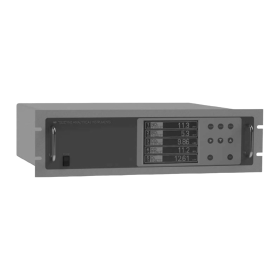
Power Supply Cord (1) (when power input is specified) • 2.2 Name and Description of Analyzer The operator interface is shown in Figure 2-1A and the various connections to the instrument are shown in figure 2-1B. Figure 2-1A: Model 7500ZA Front Panel Teledyne Analytical Instruments... -
Page 21: Figure 2-1B: Model 7500Za Rear Panel
NDIR Gas Analyzer Operation Figure 2-1B: Model 7500ZA Rear Panel Teledyne Analytical Instruments... - Page 22 Items Included with Analyzer Model 7500ZA [Blank page] Teledyne Analytical Instruments...
-
Page 23: Installation
NDIR Gas Analyzer Instalation Installation Installation of the Model 7500ZA NDIR Analyzer includes: • Unpacking • Mounting • Gas connections • Electrical connections • Calibration DANGER: THIS UNIT IS NOT AN EXPLOSION-PROOF INSTRUMENT. DO NOT USE IT IN A PLACE WITH EXPLOSIVE GASES TO PREVENT EXPLOSION, FIRE OR OTHER SERIOUS ACCIDENTS. -
Page 24: Installation Conditions
Installation Model 7500ZA 3.1 Installation Conditions To install the analyzer for optimum performance, select a location that meets the following conditions; 1. This instrument is designed for rack mounting in a standard 19” equipment rack. 2. Indoor use only. 3. Vibration-free. -
Page 25: Piping
• Pipe connection port fittings are NPT 1/4” female thread (or 1/4” RC). Piping should be cut as short as possible for optimum response. About 4 mm inner diameter is recommended. Teledyne Analytical Instruments... - Page 26 OPENED, USE A NEW FERRULE AND CONE TO SECURE A GAS TIGHT SEAL. EACH FITTING MUST BE LEAK CHECKED WHENEVER A CONNECTION HAS BEEN OPENED OR DISTURBED IN ANY MANNER. The internal piping diagram for the Model 7500ZA is shown below. Teledyne Analytical Instruments...
- Page 27 Single component None NO, CO , CO or CH Two measured species: None , CO Two measured species: NO/CO CO/SO NO/CO, NO/SO Three measured species: NO/ SO / CO Four measured species: NO/CO NO/ SO / CO Teledyne Analytical Instruments...
-
Page 28: Sampling
Installation Model 7500ZA 3.4 Sampling 3.4.1 Sample Gas Conditioning 1. Dust from the sampling gas should be completely removed using a filter. For the final stage filter, use a filter that removes dust particles down to 0.3µm. 2. Dew point must be lower than the ambient temperature. If vapor is contained in the sample, dew point should be lowered to 2°C... -
Page 29: Internal Purging Of The Instrument Housing
The purge flow rate should be set to about 1L/min. The purge gas must be free of dust and moisture. 3.4.5 Pressure at Sample Outlet Pressure at the sample gas outlet should be atmospheric pressure. Make sure there are no kinks or obstructions in the exhaust line. Teledyne Analytical Instruments... -
Page 30: Example Configuration Of Sample System
Installation Model 7500ZA 3.4.6 Example Configuration of Sample System The following illustrates a typical sample system configuration for five component gas measurement monitoring a combustion exhaust gas from boiler, refuse incinerator, etc. Contact TAI for other system configurations to match your specific application. -
Page 31: Electrical Connections
• Select a proper wiring material that satisfies the ratings of the instrument. • Be sure to connect a power supply of correct rating. The power terminal block and external input/output connector are installed on the rear panel. Refer to the diagram below. Teledyne Analytical Instruments... - Page 32 Installation Model 7500ZA (1) Power Supply (standard terminal 1 to 2) Connect the power supply to the power terminal, and connect the ground wire to the grounding terminal (standard terminal 3). Be sure to provide a protective earth connection. Use solderless terminals (for M4) for connection to the terminals (power and earth).
- Page 33 30 meters or leads to outdoors. (3) O2 Sensor Input: External input connector (A/I) Input signal: External zirconia O sensor: Zirconia O sensor signal (Fuji ZFK7 output) External O sensor: 0 to 1 VDC (DC input resistor of 1MW or more) Teledyne Analytical Instruments...
- Page 34 Installation Model 7500ZA • Used when the external zirconia O sensor or the external O sensor is ordered. It is not required or used if the analyzer has a built-in O sensor. • Connect the dedicated connector (accessory) to the output of the...
- Page 35 (DIO 1 to 3) Contact input signal : Voltage is applied from the external 12 to 24 V DC, max 15mA. Photo-coupler isolation (from each DI and ground) Contact capacity : C contact relay output 24V/1A AC/DC resistive load Teledyne Analytical Instruments...
- Page 36 Installation Model 7500ZA Teledyne Analytical Instruments...
- Page 37 (5) Communication: RS-485 connector (6) Timing of Contact Output for Calibration 1. Manual calibration: (See “Item 6.8 Calibration” if the analyzer is equipped with the auto calibration feature). Teledyne Analytical Instruments...
- Page 38 Installation Model 7500ZA 2. Automatic calibration: (See also Section 6.4: Automatic Calibration Settings) Teledyne Analytical Instruments...
- Page 39 NDIR Gas Analyzer Instalation [Blank page] Teledyne Analytical Instruments...
-
Page 41: Operation
4. After the warm-up period, perform the zero/span calibration as described in Section 6.8 Calibration. 5. After calibrating the analyzer, introduce sample gas into the analyzer and allow the lines to purge before accepting the measurement value. Teledyne Analytical Instruments... - Page 42 Installation Model 7500ZA [Blank page] Teledyne Analytical Instruments...
-
Page 43: Display And Operation Panels
Display and Operation Panels Display And Operation Panels This section describes the display unit and operation panel on the Model 7500ZA as well as the various functions available to the user. 5.1 Front Panel Description Display unit: The measurement screen and the setting items are displayed. - Page 44 Display and Operation Panels Model 7500ZA Name Description Name Description (1) MODE key Used to switch the mode. (5) ESC key Used to return to the previous screen or cancel the setting midway. Used to change the selected item (by...
-
Page 45: Overview Of Display And Operation Panels
NDIR Gas Analyzer Display and Operation Panels 5.2 Overview of Display and Operation Panels Teledyne Analytical Instruments... -
Page 46: Outline Of Display Screen
Display and Operation Panels Model 7500ZA 5.3 Outline of Display Screen (1) Measurement mode screen (appears when the power is turned on) The measurement screen depends on the number of components. The following screen configuration is shown as an example for NO,... - Page 47 * The measurement ranges for O correction concentration value and O correction concentration average value are the same as the measuring components. Also, the measurement range of the average value is the same as for O Teledyne Analytical Instruments...
- Page 48 Display and Operation Panels Model 7500ZA (2) Setting/Selection Screen The setting/selection screen is configured as shown below: • In the status display area, the current display item is displayed. • In the message display area, messages associated with operation are displayed.
- Page 49 NDIR Gas Analyzer Display and Operation Panels (3) Contents of Measured Channel (Ch) The following table gives measurement channels and their contents according to the symbols. • Teledyne Analytical Instruments...
-
Page 50: Basic Operation
Display and Operation Panels Model 7500ZA 5.4 Basic Operation • Measurement mode The measurement mode can display up to 5 channels in a single screen. If 5 channels or more are to be displayed in a single screen, press the UP or DOWN key to scroll the channels one by one. -
Page 51: Settings And Calibration
5. The selected range switch mode will be highlighted. Press the UP or DOWN key to select the desired mode. 6. Then press the ENT key to confirm the selection. 7. If “MR” is selected, the cursor moves to “Range Switch.” Teledyne Analytical Instruments... -
Page 52: Manual Range Mode
Settings and Calibration Model 7500ZA 6.1.2 Manual Range Mode The analysis range for the measured component can be switched manually as follows: 1. (1) Select “MR” as range switch mode, and then press the ENT key. 2. Using the UP/DOWN keys, move the cursor to the desired range selection. -
Page 53: Calibration Setting
Span) by pressing the UP, DOWN or SIDE (>) key. The SIDE key only functions within the selected channel. Press the ENT key when the cursor is in the desired field. The first digit of the parameter is highlighted. Teledyne Analytical Instruments... -
Page 54: Manual Zero Calibration
Settings and Calibration Model 7500ZA 4. Enter calibration gas concentration for zero and span. Use the UP or DOWN key to increment or decrement the displayed value one digit at a time. When the correct number is displayed for that digit, use the SIDE key to move to the next digit and repeat the increment/decrement process with the UP/DOWN keys. - Page 55 Select the Ch (component) on the manual zero calibration screen and then perform the zero calibration. • Setting “at once” In a manual zero calibration, Ch (components) for which “at once” are selected will simultaneously be zero-calibrated. Teledyne Analytical Instruments...
-
Page 56: Setting The Calibration Range
Settings and Calibration Model 7500ZA 6.2.3 Setting the Calibration Range This mode is used to set whether the channels use one or both of the calibration ranges. 1. From the Calibration Parameters screen, select Calibration Range. The following screen appears. - Page 57 Range 2: 0 to 2000 ppm Ch1: Range 1 and Range 2 are calibrated together Ch2: Only the currently displayed range is calibrated Note: When “both” is selected, the same calibration gas concentration must be used for both ranges. Teledyne Analytical Instruments...
-
Page 58: Setting The Component/Range For Auto Calibration
Settings and Calibration Model 7500ZA 6.2.4 Setting the Component/Range for Auto Calibration In this section you can select the Ch (component) and the range to calibrate on for those components that have the auto ranging (AR) feature enabled. 1. From the User Mode screen select <... - Page 59 Ch (component) that have “enable” set in the Auto Calibrations Setting screen. Note: ZERO calibrations for components which have been set to “enable” in the Auto Calibration Settings screen (above) are performed in batch irrespective of the description in “6.2.2 Manual Zero Calibration.” Teledyne Analytical Instruments...
-
Page 60: Alarm Setting
Settings and Calibration Model 7500ZA 6.3 Alarm setting 6.3.1 Setting Alarm Parameters The High/Low limit concentration alarms are user adjustable. Five different alarm contact outputs can be used. The setting range is 0- 100% full scale for each range. To change the alarm setting, set the alarm ON/OFF setting to OFF, and then change the value. - Page 61 When an H-limit alarm occurs, the “H-alarm” message displays in the relevant component field. Other alarm displays are: L-alarm for Low-limit alarm, HH- alarm for high limit alarm, HH-alarm for high-high alarm, and LL-alarm for low- low alarm. Teledyne Analytical Instruments...
-
Page 62: Hysteresis Setting
Settings and Calibration Model 7500ZA 6.3.2 Hysteresis Setting The alarm hysteresis can be set or changed to prevent chattering of an alarm output about its alarm set point. To set or change the alarm hysteresis: 1. Navigate to the “Alarm Setting” screen and then move the cursor to “Hysteresis”... -
Page 63: Peak Alarm Setting
(closed). Hysteresis : To prevent possible chattering when the measuring value may exceed the set peak concentration by only 1 time, the peak count has an allowance in the hysteresis width. Teledyne Analytical Instruments... - Page 64 Settings and Calibration Model 7500ZA Setting Range → 5 ppm step (initial value: 500 ppm) Alarm value: 10-1000 ppm → (initial value: 5 times) Alarm count: 1- 99 times/hr → (initial value: 0% of full scale) Hysteresis : 0-20 % FS [% FS] represents the percentage with the CO range regarded as 100%.
-
Page 65: Setting Up The Auto Calibration
When all the settings are correct, press the ENT key to save them. Subsequent auto calibrations will use the saved settings. Description of Auto Cal Settings • Start Time : Setting for the first calibration event (day of the week, hour, minute) Teledyne Analytical Instruments... - Page 66 Settings and Calibration Model 7500ZA • Cycle : The period between the start time of one calibration and the next (unit: hour/day) • Flow Time : The time required for purging with calibration gas. Time required for replacement of sample gas after the calibration is completed (Set by calibration gas.
- Page 67 CH 4 Span 300 sec CH 5 Span 300 sec Ex. Time 300 sec ON/OFF Thus, with the above settings: Setting Range: Cycle: 1-99 hours or 1-40 days (default value—7days) Flow Time: 60-90 sec (default value—300 sec) Teledyne Analytical Instruments...
-
Page 68: Forced Run/Stop Of Auto Calibration
Settings and Calibration Model 7500ZA Caution: When an auto calibration starts, the measurement screen appears automatically. Any operation other than “Stop Auto Calibration” (see Item 6.4.2) is not permitted during auto calibration. “Stop Auto Calibration” cannot be performed with the key lock to ON. -
Page 69: Forced Stop Of Auto Calibration
(see Section 6.2.4): • Zero calibration A message, “Zero cal.” blinks at Ch1 and Ch2. • Ch1 span calibration A message, “Span cal.” blinks at Ch1. • Ch2 span calibration A message, “Span cal.” blinks at Ch2. Teledyne Analytical Instruments... - Page 70 Settings and Calibration Model 7500ZA Caution: During an auto calibration, all key operations are not permitted other than key lock ON/OFF and “Auto Calibration Stop.” When the key lock is ON, the “Auto Calibration Stop” is locked out as well.
-
Page 71: Setting Auto Zero Calibration
Description of Auto Zero Settings • Start Time : Setting for the first calibration event (day of the week, hour, minute) • Cycle : The period between the start time of one calibration and the next (unit: hour/day) Teledyne Analytical Instruments... - Page 72 Settings and Calibration Model 7500ZA • Flow Time: The time required for purging with calibration gas. Time required for replacement of sample gas after the calibration is completed (Set by calibration gas. See the next page.) • ON/OFF: Turns the auto calibration feature ON or OFF.
-
Page 73: Forced Run/Stop Of Auto Zero Calibration
A remote start input will begin a calibration event regardless of whether the auto zero calibration is set to ON or OFF. 6.5.2 Forced Run/Stop of Auto Zero Calibration Auto zero calibration can be performed just once, or auto zero calibration can be forcibly stopped during calibration. Teledyne Analytical Instruments... -
Page 74: Execution Of Auto Zero Calibration (Only Once)
Settings and Calibration Model 7500ZA 6.5.2.1 E XECUTION OF AUTO ZERO CALIBRATION ONLY ONCE 1. In the “Setting of Auto Zero Calibration” screen that appears, point the cursor to “Run” by pressing the UP or DOWN key. Then press ENT. - Page 75 ON/OFF and “Auto Zero Calibration Stop.” When the key lock is set at ON, even the “Auto Zero Calibration Stop” cannot be used. To forcibly stop “auto zero calibration”, set the key lock to OFF and then execute “Auto Zero Calibration Stop.” Teledyne Analytical Instruments...
-
Page 76: Parameter Setting
Settings and Calibration Model 7500ZA 6.6 Parameter Setting From the Parameter Setting screen you can set or adjust various parameters of the instrument such as time, key lock, etc. Settable items are as follows: Description of setting items • Current Time : Current year, month, date, day of the week, hour, and minute setting. - Page 77 (see Section 6.4, Setting of Auto Calibration). However, an output signal can be held via an external input regardless of the Hold ON/OFF setting. Teledyne Analytical Instruments...
- Page 78 Settings and Calibration Model 7500ZA Manual Calibration Auto Calibration Remote Input Screen Display During Holding A “Hold ON” message will blink on the measuring screen during a hold period. Teledyne Analytical Instruments...
- Page 79 (1). Pressing the ENT key while “Setting” is selected will bring up the parameter hold screen where an arbitrary hold value can be set. Teledyne Analytical Instruments...
- Page 80 Settings and Calibration Model 7500ZA 4. On the parameter hold screen that appears, move the cursor to the Ch (component) you want to hold using the UP or DOWN key and then press ENT. 5. A highlighted value indicates that it can be changed.
- Page 81 (1-minute step) or 1 to 4 hours (1-hour step). Changing the setting also resets the averaging of O correction and O average value. (Pressing the ENT key resets averaging only for the components whose setting were changed.) Teledyne Analytical Instruments...
- Page 82 Settings and Calibration Model 7500ZA Average Value Reset This mode is used to clear all average values, i.e. O correction average and O average, and restarts averaging. All average values are reset simultaneously. The indication value and output value is 0 ppm, vol% or so at the time of the reset input (based on average period settings).
- Page 83 The next section describes in detail the functions available in maintenance mode. The default password is set at the factory to “0000.” You can enter the maintenance mode with this value before changing the password in maintenance mode to one of your choosing. Teledyne Analytical Instruments...
-
Page 84: Maintenance Mode
3. Press the ESC key to return to the Maintenance Mode item selection screen from each screen. 6.7.1 Sensor Input Value screen There are 5 possible inputs on the Model 7500ZA: 1. Input 1 to 4 : NDIR sensor digital value 2. Input 5 : O2 sensor digital value 6.7.2 Error Log screen... -
Page 85: Calibration Log Screen
Z1 : Zero calibration (Z) of Range 1 S1 : Span calibration (S) of Range 1 Cnt : Value of measuring detector at the time of calibration Con : Concentration value displayed before calibration YDMH: Time of calibration event Teledyne Analytical Instruments... -
Page 86: Output Adjustment Screen
Settings and Calibration Model 7500ZA 6.7.4 Output Adjustment Screen The Analog Output Adjustment screen allows the user to adjust the 0-1 V and 4-20 mA output signal. Connect a digital multi meter to the specific output terminal requiring adjustment and adjust the value so that 4 mA or 0 V is output at zero concentration and 20mA or 1V is output at full scale or span. -
Page 87: Other Parameter
It is settable in the range from 01 to 20%. * Refer to the O2 correction concentration value in “5.3 Outline of display screen” for oxygen correction calculation procedure. Teledyne Analytical Instruments... - Page 88 Settings and Calibration Model 7500ZA Station No. This function allows the user to set the station No. for MODBUS communication. It is settable in the range from 00 to 32. Range Setting This function brings up a screen where the user can set the range for which concentration measurements are made.
-
Page 89: Calibration
“Setting of Auto Calibration Component/Range” (6.2.4), and calibration is carried out on that range. To close the Zero Calibration screen or to abort the entry midway, press the ESC key. The previous screen will return. Teledyne Analytical Instruments... -
Page 90: Span Calibration
Settings and Calibration Model 7500ZA 6.8.2 Span Calibration The Model 7500ZA requires periodic span calibration at or near the full scale value on the range of interest. It requires a prepared standard gas containing a known concentration of the measured species. -
Page 91: Maintenance
Flow rate check 1. Sample and purge gas flow rates are as follows: Sample gas flow : 0.5L/min ± 0.2L/min Purge gas flow : About 1L/min 2. Instrument checks and maintenance should be carried out every day, as required. Teledyne Analytical Instruments... -
Page 92: Daily Check And Maintenance Procedures
Maintenance Model 7500ZA 7.2 Daily Check And Maintenance Procedures Table 7.1 Maintenance and Check Table 7.3 Long Term Maintenance Create a long-term maintenance component procurement plan based on the “Gas analyzer annual inspection plan” indicated below. Gas Analyzer Annual Inspection Plan The recommended replacement period of components varies depending on the installation conditions. - Page 93 , 0 to 2000 ppm CO, 5% to 15% CO , 0% to 21%O , 0 to 100 ppm HCl, residue N Please consult TAI Customer Service regarding gas analyzer maintenance service requirements. Annual Inspection Plan Sheet Teledyne Analytical Instruments...
-
Page 94: Cleaning The Sample Cell
7.4.1 Sample Cell Disassembly There are two kinds of sampling cells used in the Model 7500ZA:, block cells (cell length: 4 mm, 8 mm, 16 mm, 32 mm) and pipe cells (cell length: 64 mm, 125 mm, 200 mm and 250 mm). -
Page 95: Pipe Cell Removal (See Fig. 7-1)
(No. 11) at both ends of the pipe cell. 6. Remove the cell from the assembly and unscrew the infrared transmission window (No. 14) at both ends. 7. For assembly, reverse the disassembly procedure. Figure 7-1: Measuring Unit Configuration (Pipe Cell) Teledyne Analytical Instruments... -
Page 96: Block Cell Removal (See Fig. 7-2)
Maintenance Model 7500ZA 7.4.1.2 B . 7-2) LOCK EMOVAL For steps 1 to 4, see 7.4.1.1, Pipe Cell Removal. 5. Disconnect and remove detector output cables from detector output circuit board (No.12). Applying identification mark on top of removed cable connector will ensure proper pin assignment later. -
Page 97: Figure 7-2: Measuring Unit Configuration (Block Cell)
NDIR Gas Analyzer Maintenance Figure 7-2: Measuring Unit Configuration (Block Cell) Teledyne Analytical Instruments... -
Page 98: Removing The Measuring Unit
Maintenance Model 7500ZA 7.4.1.3 R EMOVING THE EASURING Refer to Fig. 7-3. For step 1 to 4, see 7.4.1.1, Pipe Cell Removal. 5. Disconnect and remove detector output cables from detector output circuit board (No.12). Applying identification mark on top of removed cable connector will ensure proper pin assignment later. - Page 99 NDIR Gas Analyzer Maintenance Figure 7-3: Measuring Unit with 2-Component Block and Pipe Cell Teledyne Analytical Instruments...
-
Page 100: Fuse Replacement
Maintenance Model 7500ZA 7.5 Fuse Replacement 1. Turn “OFF” the main power supply switch to the analyzer. 2. Rotate the fuse holder cap (shown in the figure above) counterclockwise and pull it out. The cap (fuse holder) will contain the fuse. Remove the blown fuse from the holder and replace it with a new one (250VAC/2A, Slo-Blo). -
Page 101: Error Messages
Table 8-1: Error Messages When errors No. 1 to No. 3 and No. 10 occur, analyzing block error contact output closes. When errors No. 4 to No. 9 occur, the calibration error contact output closes. Teledyne Analytical Instruments... -
Page 102: Troubleshooting
Error Messages Model 7500ZA 8.1 Troubleshooting When error No. 1 occurs, remove the top cover of the analyzer and check the LED on the light source PCB. If the LED is off, then the error is caused by a light source disconnection. -
Page 103: Error Log File
When more than one error occurs, use the SIDE key to move to the next error display. For errors 5 and 7: 8.2 Error Log File When an error occurs, the history is saved in an error log file. The error log file is accessible in the maintenance mode. Teledyne Analytical Instruments... - Page 104 Error Messages Model 7500ZA Error Log Screen * Up to 14 errors can be saved in the error history; the oldest error will be deleted one by one every time a new error occurs. * If the power supply is turned OFF, the contents in the error log file will not be lost or damaged.
-
Page 105: Specifications
0-200 ppm 0-5000ppm 0-200 ppm 0-10 vol.% 0-100 ppm 0-100 vol.% 0-200 ppm 0-100 vol.% 0-500 ppm 0-100 vol.% 0-10 vol.% 0-25 vol.% (built in) Fuel Cell 0-5 vol.% 0-100 vol.% (built in) None 100-95 vol.% Paramag. Teledyne Analytical Instruments... - Page 106 Specifications Model 7500ZA 0-5 vol.% 0-25 vol.% External Zirconia Max. 5 components measurement including O For reverse range O measurement, IR gas measurement is not available (single range only). Measuring range ratio max. 1:10 (except User adjustable ranges between the specified minimum and maximum range.
- Page 107 Digital Input: (option) Voltage contact (supply 12-24VDC (15mA Max.)) Max. 9 inputs Remote range change over, auto calibration remote start, remote hold, average value reset, Isolated from the internal circuit with photocoupler. Teledyne Analytical Instruments...
- Page 108 Specifications Model 7500ZA Voltage rating: 100V to 240V AC Power Supply: Allowable range: 85V to 264V AC Frequency: 50Hz/60Hz Power consumption: 100VA max. Operating Conditions: Ambient temperature: -5˚C to 45˚C (40˚C max. when 2 optical system at 200V AC power...
-
Page 109: Standard Functions
* The switch range values are settable between the first range and second range values (low/high range values). Teledyne Analytical Instruments... -
Page 110: Optional Functions
Specifications Model 7500ZA 9.1.3 Optional Functions Remote Output Holding: Output signal is held at the last value or preset value by a voltage input to the remote output holding input terminals. Holding is maintained while the voltage is input to the terminals. Indication of instantaneous values are not held. - Page 111 Contacts turn on at occurrence of manual or auto calibration errors from 4-9. Auto Cal Status Contact Outputs: Contacts turn on during auto calibration. O2 Correction: Correction of measured NO, SO and CO gas concentrations into values at reference concentration Teledyne Analytical Instruments...
- Page 112 Specifications Model 7500ZA Correction formula: − × − C : Sample gas concentration after O correction. Cs : Measured concentration of sample gas. Os : Measured O concentration (Limit setting: 1 to 20% O On : Reference O concentration (value...
- Page 113 (for use, exhaust port of analyzer must be at atmospheric pressure. After atmospheric pressure correction: Zero point: Not affected. Span point: Change is 0.5% measured value or less relative to a 1% change in atmospheric pressure. Correction range: 700hPa-1050hPa Teledyne Analytical Instruments...
-
Page 114: Performance
Specifications Model 7500ZA 9.1.4 Performance Repeatability: ±0.5% of full scale Linearity: 1% of full scale prior to atmospheric pressure correction (option) Zero drift: ±2% of full scale/week. For auto zero calibration use 500ppm or lower range. Span drift: ±2% of full scale/week Response time (for 90% FS response): 1 to 15 sec electrical response. -
Page 115: Requirements For Sample Gas
1) Infrared-ray measurable component, standard O Zero gas: Dry N Span gas ; Each sample gas having concentration 90 to 100% of its measuring range recommended). For external zirconia O sensor use the same calibration gas line: Teledyne Analytical Instruments... -
Page 116: Installation Requirements
Specifications Model 7500ZA Zero gas ; Dry air or atmospheric air (Do not use with CO measurement) Span gas ; For other than O measurement, each sample gas having concentration 90 to 100% of its measuring range. For O measurement, O... - Page 117 More than two components analyzer: 1. The 2nd range in the tables for two and more components is maximum available range. 2. Select the 2nd range less than or equal to the “2nd range (max)”. Teledyne Analytical Instruments...
- Page 118 Specifications Model 7500ZA Teledyne Analytical Instruments...
- Page 119 NDIR Gas Analyzer Specifications Teledyne Analytical Instruments...
- Page 120 Specifications Model 7500ZA Teledyne Analytical Instruments...
- Page 121 NDIR Gas Analyzer Specifications Teledyne Analytical Instruments...
- Page 122 Specifications Model 7500ZA 9.3 Code Symbols Teledyne Analytical Instruments...
- Page 123 When English is specified for display language, “E” should be selected at 20th digit. note6) O2 correction is calculated only for NO, SO2 and CO. note7) When 5 components measurement is specified, “H” must not be specified at 22nd digit. Teledyne Analytical Instruments...
- Page 124 Specifications Model 7500ZA When 4 components measurement is specified and “H” is specified at 22nd digit, 3 points is maximum for alarm output function. note8) When “B” is specified at 24th digit, measuring range should be specified by ppm range code. In this case NO, SO2 and CO measuring range are corresponding range in mg/m3.
- Page 125 NDIR Gas Analyzer Specifications 9.4 Outline Diagram <Analyzer main unit> Teledyne Analytical Instruments...
- Page 126 Specifications Model 7500ZA [Blank page] Teledyne Analytical Instruments...
Need help?
Do you have a question about the 7500ZA and is the answer not in the manual?
Questions and answers