Table of Contents
Advertisement
Quick Links
Information contained herein is classified as EAR99 under the
U.S. Export Administration Regulations.
Export, reexport or diversion contrary to U.S. law is prohibited.
OPERATING INSTRUCTIONS FOR
Model
(ATEX)
Percent Oxygen Analyzer
HIGHLY TOXIC AND OR FLAMMABLE LIQUIDS OR GASES MAY BE PRESENT IN THIS MONITORING
SYSTEM.
PERSONAL PROTECTIVE EQUIPMENT MAY BE REQUIRED WHEN SERVICING THIS SYSTEM.
HAZARDOUS VOLTAGES EXIST ON CERTAIN COMPONENTS INTERNALLY WHICH MAY PERSIST
FOR A TIME EVEN AFTER THE POWER IS TURNED OFF AND DISCONNECTED.
ONLY AUTHORIZED PERSONNEL SHOULD CONDUCT MAINTENANCE AND/OR SERVICING. BEFORE
CONDUCTING ANY MAINTENANCE OR SERVICING CONSULT WITH AUTHORIZED SUPERVISOR/
MANAGER.
Teledyne Analytical Instruments
Use and Disclosure of Data
Percent Oxygen Analyzer
3020P
DANGER
P/N M95012
3/29/19
i
Advertisement
Table of Contents

Related Manuals for Teledyne Analytical Instruments 3020P


Summary of Contents for Teledyne Analytical Instruments 3020P
- Page 1 HAZARDOUS VOLTAGES EXIST ON CERTAIN COMPONENTS INTERNALLY WHICH MAY PERSIST P/N M95012 FOR A TIME EVEN AFTER THE POWER IS TURNED OFF AND DISCONNECTED. 3/29/19 ONLY AUTHORIZED PERSONNEL SHOULD CONDUCT MAINTENANCE AND/OR SERVICING. BEFORE CONDUCTING ANY MAINTENANCE OR SERVICING CONSULT WITH AUTHORIZED SUPERVISOR/ MANAGER. Teledyne Analytical Instruments...
- Page 11 Description: Oxygen measuring device for use in hazardous rated areas. It is suitable for measuring Oxygen concentrations up to 20.9% in a variety of hazardous and non- hazardous gasses. This device is suitable for use with gasses rated up to and including IIB+H2.
- Page 12 Standards: IEC 60079-0:2017 Equipment general requirements IEC 60079-1:2014 Equipment protection by flameproof enclosures “d” Conditions for Safe use Symbol X: “Warning- This instrument is not designed for use with oxygen enriched gasses, ie. Gasses with oxygen content greater than 21%. “Warning- Do to the presence of a window, this analyzer shall be located in an area of low impact.
- Page 15 Teledyne Analytical Instruments, 16830 Chestnut Street, City of Industry, CA 91748. Warranty...
- Page 16 In addition to all standard features, this model also has separate ports for zero and span gases, and built-in control valves. The internal valves are entirely under the control of the 3020P electronics, to automatically switch between gases in synchronization with the analyzer’s operations. 3020P (ATEX)-S: q q q q q Stainless steel sampling system and cell block.
-
Page 17: Table Of Contents
Model 3020P (ATEX) Table of Contents 1 Introduction 1.1 Overview ................ 1-1 1.2 Typical Applications ............1-1 1.3 Main Features of the Analyzer ........1-1 1.4 Model Designations ............1-2 1.5 Operator Interface ............1-3 1.5.1 UP/DOWN Switch ..........1-4 1.5.2 ESCAPE/ENTER Switch ........ - Page 18 4.13 The SENSOR Function ..........4-17 4.14 The Analysis Mode ............4-17 Maintenance 5.1 Routine Maintenance ............. 5-1 5.2 Major Internal Components ..........5-1 5.3 Cell Replacement ............5-2 5.3.1 Storing and Handling Replacement Cells ....5-2 Teledyne Analytical Instruments...
- Page 19 Model 3020P (ATEX) 5.3.2 When to Replace a Cell ........... 5-3 5.3.3 Removing the Micro-Fuel Cell ......... 5-4 5.3.4 Installing a New Micro-Fuel Cell ......5-6 5.2.5 Cell Warranty ............5-6 5.4 Fuse Replacement............5-7 5.5 System Self Diagnostic Test ........... 5-7 Appendix A-1 Specifications ..............
-
Page 20: Introduction
Overview The Teledyne Analytical Instruments Model 3020P (ATEX) Percent Oxygen Analyzer is a versatile microprocessor-based instrument for detecting oxygen in a variety of gases. This manual covers the Model 3020P (ATEX), percent oxygen, explosion-proof, bulkhead-mount units only. Typical Applications A few typical applications of the Model 3020P (ATEX) are: •... -
Page 21: Model Designations
In addition to all standard features, this model also has separate ports for zero and span gases, and built-in control valves. The internal valves are entirely under the control of the 3020P electronics, to automatically switch between gases in synchronization with the analyzer’s operations. 3020P (ATEX)-S: Stainless steel cell block and sampling system. -
Page 22: Operator Interface
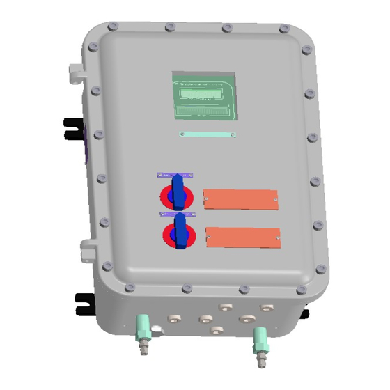
Percent Oxygen Analyzer Introduction 1 Operator Interface All controls and displays on the standard 3020P (ATEX) are accessible from outside the housing. The instrument has two simple operator controls. The operator has constant feedback from the instrument through an alphanumeric display, a digital oxygen meter, and a sample flow meter. The displays and controls are described briefly here and in greater detail in chapter 4. -
Page 23: Up/Down Switch
Model 3020P (ATEX) 1 Introduction Figure 1-1: Model 3020P Controls, Indicators, and Connectors 1.5.1 UP/DOWN Switch Functions: The UP/DOWN switch is used to select the function to be performed. Choose UP or DOWN to scroll through the following list of twelve functions: •... -
Page 24: Escape/Enter Switch
Digital Meter Display: The meter display is a LED device that produces large, bright, 7-segment numbers that are legible in any lighting. It produces a continuous readout from 0-100 %. It is accurate across all analysis ranges without the discontinuity inherent in analog range switching. Teledyne Analytical Instruments... -
Page 25: Recognazing Difference Between Lcd & Vfd
Model 3020P (ATEX) 1 Introduction Alphanumeric Interface Screen: The backlit VFD screen is an easy- to-use interface from operator to analyzer. It displays values, options, and messages that give the operator immediate feedback. Flowmeter: Monitors the flow of gas past the sensor. Readout is 0.2 to 2.4 standard liters per minute (SLPM). - Page 26 115 or 230 V dc, 50 or 60 Hz. • Analog Outputs 0-1 V dc concentration plus 0-1 V dc range ID. Additional, isolated 4-20 mA dc plus 4-20 mA dc range ID available. • Alarm Connections 2 concentration alarms and 1 system alarm. Teledyne Analytical Instruments...
-
Page 27: Gas Connector Panel
The gas connector panel, shown in Figure 1-3, contains the gas con- nections for external inlets and outlets. Those that are optional. The connectors are described briefly here and in detail in the Installation chapter of this manual. Figure 1-3: Model 3020P(ATEX) Optional Gas Panel and Auto-Cal valves Teledyne Analytical Instruments... -
Page 28: Introduction 1
Note: If you require highly accurate Auto-Cal timing, use external Auto-Cal control where possible. The internal clock in the Model 3020P is accurate to 2-3 %. Accordingly, internally scheduled calibrations can vary 2-3 % per day. Fig. 1-4 3020(ATEX) shown with optional auto-cal valves. - Page 29 Model 3020P (ATEX) 1 Introduction Fig 1.5 3020(ATEX) Std. version Teledyne Analytical Instruments 1-10...
-
Page 30: Micro-Fuel Cell Sensor
Micro-Fuel Cell Sensor 2.2.1 Principles of Operation The oxygen sensor used in the Model 3020P (ATEX) series is a Micro- Fuel Cell designed and manufactured by Analytical Instruments. It is a sealed plastic disposable electrochemical transducer. -
Page 31: Anatomy Of A Micro-Fuel Cell
Model 3020P (ATEX) 2 Operational Theory comes from outside the device as a constituent of the sample gas being analyzed. The Micro-Fuel Cell is therefore a hybrid between a battery and a true fuel cell. (All of the reactants are stored externally in a true fuel cell.) 2.2.2 Anatomy of a Micro-Fuel Cell... -
Page 32: Electrochemical Reactions
The overall reaction for the fuel cell is the SUM of the half reactions above, or: → 2PbO 2Pb + O (These reactions will hold as long as no gaseous components capable of oxidizing lead—such as iodine, bromine, chlorine and fluorine—are present in the sample.) Teledyne Analytical Instruments... -
Page 33: The Effect Of Pressure
Model 3020P (ATEX) 2 Operational Theory The output of the fuel cell is limited by (1) the amount of oxygen in the cell at the time and (2) the amount of stored anode material. In the absence of oxygen, no current is generated. -
Page 34: Micro-Fuel Cell "Class
1 % and 100 % in the sample gas. Nominal output in air is 0.20 mA, and 90 % response time is 45s. Expected life in flue gas is 8 months. Teledyne Analytical Instruments... -
Page 35: Sample System
Model 3020P (ATEX) 2 Operational Theory 2.2.6.2 Class A-5 Cell The class A-5 cell is for use in applications where it is exposed intermit- tently to carbon dioxide concentrations up to 100 % in the sample gas. Nominal output in air is 0.19 mA, and 90 % response time is 45 s. -
Page 36: Electronics And Signal Processing
Sample In port by teeing to the port with appropriate valves. The left side of the diagram shows the components added when the –C options are ordered. The valves, when supplied, are installed inside the 3020P enclosure and are regulated by the instruments internal electronics. The flame arrestors, when supplied, are installed in the Gas Connector Panel. - Page 37 The preamplifier board is mounted on top of the motherboard. These boards are accessible after removing the access panel. Figure 2-5 is a block diagram of the Analyzer electronics. Figure 2-5: Block Diagram of the Model 3020P Electronics Teledyne Analytical Instruments...
-
Page 38: Temperature Control
2.5 Temperature Control For accurate analysis this instrument is temperature controlled not to fall C. This is to prevent beneath a certain temperature. This temperature is 22 the sensor from freezing in cold environments. Teledyne Analytical Instruments... - Page 39 Model 3020P (ATEX) 2 Operational Theory Teledyne Analytical Instruments 2-10...
-
Page 40: Installation
Immediately report any damage to the shipping agent. Mounting the Analyzer The Model 3020P is designed for bulkhead mounting in hazardous environments. There are four mounting lugs—one in each corner of the enclosure, as shown in Figure 3-1. The outline drawing, at the back of this manual, gives the mounting hole size and spacing. - Page 41 Model 3020P (ATEX) 3 Installation Figure 3-1: View of the Model 3020P (ATEX) WITH OPTIONAL GAS PANEL Teledyne Analytical Instruments...
-
Page 42: Electrical Connections
Percent Oxygen Analyzer Installation 3 Figure 3-2: Required Front Door Clearance Electrical Connections Figure 3-3 shows the Model 3020P Electrical Connector Panel. There are terminal blocks for connecting power, communications, and both digital and analog concentration outputs. Figure 3-3: Electrical Connector Panel... -
Page 43: Primary Input Power
Model 3020P (ATEX) 3 Installation For safe connections, ensure that no uninsulated wire extends outside of the connectors they are attached to. Stripped wire ends must insert com- pletely into terminal blocks. No uninsulated wiring should be able to come in contact with fingers, tools or clothing during normal operation. - Page 44 The signal output for concentration is linear over the currently selected analysis range. For example, if the analyzer is set on a range that was defined as 0–10 % O , then the output would be as shown in Table 3-1. Teledyne Analytical Instruments...
-
Page 45: Alarm Relays
Model 3020P (ATEX) 3 Installation Table 3-1: Analog Concentration Output—Example Voltage Signal Current Signal Output (V dc) Output (mA dc) 10.4 12.0 13.6 15.2 16.8 18.4 20.0 To provide an indication of the range, a second pair of analog output terminals are used. -
Page 46: Digital Remote Cal Inputs
Remote Zero and Span Inputs: The REMOTE SPAN and RE- MOTE ZERO inputs are on the DIGITAL INPUT terminal block. They accept 0 V (OFF) or 24 V dc (ON) for remote control of calibration. (See Remote Calibration Protocol below.) Teledyne Analytical Instruments... - Page 47 (See Remote Calibration Protocol below.) Remote Calibration Protocol: To properly time the Digital Remote Cal Inputs to the Model 3020P Analyzer, the customer's controller must monitor the CAL CONTACT relay. When the contact is OPEN, the analyzer is analyzing, the Remote Cal Inputs are being polled, and a zero or span command can be sent.
-
Page 48: Range Id Relays
If you have the –C Internal valve option—which includes additional zero and span gas inputs— the 3020P automatically regulates the zero, span and sample gas flow. 3.3.6 Range ID Relays There are four dedicated RANGE ID CONTACT relays. -
Page 49: Remote Sensor And Solenoid Valves
Toggling input. Stops/Starts any status message output from the RS-232, until st<enter> is sent again. The RS-232 protocol allows some flexibility in its implementation. Table 3-5 lists certain RS-232 values that are required by the 3020P imple- mentation. Table 3-5: Required RS-232 Options... -
Page 50: Installing The Micro-Fuel Cell
It must be installed before the analyzer is placed in service. Once it is expended, the Micro-Fuel Cell will need to be replaced. The cell could also require replacement if the instrument has been idle for too long. 3-11 Teledyne Analytical Instruments... -
Page 51: Gas Connections
Gas Connections The 3020P (ATEX) is configured for use with a pressurized sample source. The 3020P (ATEX) analyzers are supplied with flow restrictors installed in all of the sample in flame arrestors. They are part of the safety system. These restrictors should limit the gas flow to 1.1SLPM at 25 psig (N2 gas). - Page 52 These valves are completely under control of the 3020P Electronics. They can be externally controlled only indirectly through the Remote Cal Inputs, described below. Pressure, flow, and safety considerations are the same as prescribed for the SAMPLE IN inlet, above.
-
Page 53: Testing The System
Model 3020P (ATEX) 3 Installation Testing the System Before plugging the instrument into the power source: • Check the integrity and accuracy of the gas connections. Make sure there are no leaks. • Check the integrity and accuracy of the electrical connections. Make sure there are no exposed conductors. -
Page 54: Operation
• Establish a security password, if desired, requiring Operator to log in. Before you configure your 3020P(ATEX) these default values are in effect: Ranges: LO = 0-1 %, MED = 0-5 %, HI = 0-10 %. Auto Ranging: ON Alarm Relays: Defeated, 10 %, HI, Not failsafe, Not latching. -
Page 55: Mode/Function Selection
The MAIN MENU consists of 12 functions you can use to customize and check the operation of the analyzer. Figure 4-1 shows the functions available with the 3020P. They are listed here with brief descriptions: 1 AUTO-CAL: Used to define and/or start an automatic calibration sequence. - Page 56 HI or LO acting, latching or not, and failsafe or not. 9 RANGE: Used to set up three analysis ranges that can be switched automatically with auto-ranging or used as individual fixed ranges. Teledyne Analytical Instruments...
-
Page 57: Data Entry
Model 3020P (ATEX) 4 Operation 10 STANDBY: Remove power to outputs and displays, but maintain power to internal circuitry. 11 SENSOR: Check the condition of the Micro-Fuel Cell sensor to determine whether it should be replaced. Any function can be selected at any time. Just scroll through the MAIN MENU with the DOWN/UP control to the appropriate function, and ENTER it. -
Page 58: The Auto-Cal Function
Note: If you require highly accurate timing of your AUTO-CAL, use external AUTO-CAL control where possible. The internal clock in the Model 3020P is accurate to 2-3 %. Accordingly, internally scheduled calibrations can vary 2-3 % per day. To setup an AUTO-CAL cycle: Scroll to AUTO-CAL, and ENTER. -
Page 59: Entering The Password
Model 3020P (ATEX) 4 Operation analyze sample gas and report on alarm conditions without entering the password. • Only one password can be defined. • After a password is assigned, the operator must log out to activate it. Until then, anyone can continue to operate the instrument without entering the new password. -
Page 60: Installing Or Changing The Password
Characters Available for Password Definition: ¥ → " & < > When you have finished typing the new password, the last ENTER enters it. A verification screen appears. The screen will prompt you to retype your password for verification. Teledyne Analytical Instruments... -
Page 61: The Logout Function
Model 3020P (ATEX) 4 Operation A A A A A Retype PWD To Verify Wait a moment for the entry (<ENT>) screen. You will be given clearance to proceed. A A A A A <ENT> TO Proceed ENTER the letters of your new password. Your password will be stored in the microprocessor and the system will immediately switch to the ANA- LYZE screen, and you now have access to all instrument functions. -
Page 62: The Self Test Function
Operation 4 The SELF-TEST Function The Model 3020P has a built-in self-testing diagnostic routine. Prepro- grammed signals are sent through the power supply, output board and sensor circuit. The return signal is analyzed, and at the end of the test the status of each function is displayed on the screen, either as OK or as a number be- tween 1 and 3. -
Page 63: Cell Failure
ENTER the ZERO or SPAN function. 4.8.1. Cell Failure When the sensor in the 3020P begins to fail, the analyzer will usually require more and more frequent calibration. If the 3020P analysis readings drift downward uncharacteristically, try recalibration. If recalibration raises the readings temporarily only, suspect the cell. -
Page 64: Span Cal
Manual Mode Spanning ENTER SPAN from the MAIN MENU to start the SPAN function. The screen that appears allows you to select whether the span calibration is to be performed automatically or manually. Span: Settling:MAN <ENT> For Next Teledyne Analytical Instruments 4-11... -
Page 65: The Alarms Function
The instrument then automatically enters the ANALYZE function. The ALARMS Function The Model 3020P(ATEX) is equipped with 2 fully adjustable concentration alarms and a system failure alarm. Each alarm has a relay with a set of form “C" contacts rated for 3 amperes resistive load at 250 V ac. - Page 66 Once you have clearance to proceed, ENTER the ALARM function. AL—1 AL—2 Choose Alarm Use the DOWN/UPcontrol to blink your choice of alarm, AL-1 or AL-2. Then ENTER to move to the next screen. Teledyne Analytical Instruments 4-13...
-
Page 67: The Range Function
Med = 0–5 % High = 0–10 %. The Model 3020P is set at the factory to default to autoranging. In this mode, the microprocessor automatically responds to concentration changes by switching ranges for optimum readout sensitivity. If the current range... -
Page 68: Setting The Analog Output Ranges
DC outputs to stay in a single predetermined range. To switch from autoranging to fixed range analysis, ENTER the RANGE function by selecting RANGE from the MAIN MENU. Use the DOWN/UPcontrol to move AUTO between the arrows. Teledyne Analytical Instruments 4-15... -
Page 69: The Contrast Function
Model 3020P (ATEX) 4 Operation Use the DOWN/UPcontrol to switch from AUTO to FX/LO, FX/ MED, or FX/HI to set the instrument on the desired fixed range (low, me- dium, or high). L—1.00 M—5.00 H—10.00 Mode—FX/LO L—1.00 M—5.00 H—10.00 Mode—FX/MED L—1.00... -
Page 70: The Standby Function
After four or five seconds in the MAIN MENU without any action by the operator, the analyzer automatically switches itself back to the ANA- LYZE screen. ESCAPE, asserted one or more times, depending on the starting point, also switches the analyzer back to the ANALYZE screen. Teledyne Analytical Instruments 4-17... - Page 71 Model 3020P (ATEX) 4 Operation 4-18 Teledyne Analytical Instruments...
-
Page 72: Maintenance 5
Micro-Fuel cells and fuses, and recalibration. For recalibration, see Section 4.4 The Zero and Span Functions. WARNING: SEE 3020P (ATEX) addendum for warnings and instructions for safe use. Major Internal Components All internal components are accessed by unbolting and swinging open the front cover, as described earlier. -
Page 73: Cell Replacement
This section describes fuel cell care as well as when and how to replace it. The Class B-1 Micro-Fuel Cell is used in the standard Model 3020P(ATEX). If any other cell is supplied with your instrument, check the front of this manual for any addenda applying to your special model. -
Page 74: When To Replace A Cell
CIAN. (SEE APPENDIX, MATERIAL SAFETY DATA SHEET.) 5.3.2 When to Replace a Cell When the sensor in the 3020P begins to fail, the analyzer will usually require more and more frequent calibration. If the 3020P analysis readings drift downward uncharacteristically, try recalibration. If recalibration raises the readings temporarily only, suspect the cell. -
Page 75: Removing The Micro-Fuel Cell
Model 3020P (ATEX) 5 Maintenance Although the B-1 cell is standard in the 3020P, check Specific Model Information in the Front Matter in this manual for the class of cell you purchased. Then check Table 5-1, the Cell Indices table below, and do the prescribed calculations. - Page 76 5. When it is free, unscrew the cap from the nylon probe. Hold the probe vertically to prevent dropping the cell out of the probe. 6. Remove the cell from the probe, and dispose of it in an environmentally safe manner. Teledyne Analytical Instruments...
-
Page 77: Installing A New Micro-Fuel Cell
5.3.5 Cell Warranty The Class B-1 Micro-Fuel cell is standard in the Model 3020P(ATEX). This cell is a long life cell and is warranted for 6 months from the date of shipment. The customer should purchase only one spare cell (per section 5.3.1). Do not attempt to stockpile spare cells. -
Page 78: Fuse Replacement
Maintenance 5 Fuse Replacement The 3020P requires two 5 x 20 mm, 4 A, T type (Slow Blow) fuses. The fuses are located inside the explosion proof housing on the Electrical Connector Panel, as shown in Figure 5-2. To replace a fuse: 1. - Page 79 Model 3020P (ATEX) 5 Maintenance The module is functioning properly if it is followed by OK. A number indicates a problem in a specific area of the instrument. Refer to Table 5-1 for number-code information. The results screen alternates for a time with: Press Continue...
-
Page 80: Appendix A-1 Specifications
Displays: 2 line by 20 alphanumeric, VFD screen, and one 5 digit LED display. Digital Interface: Full duplex RS-232 communications port. Power: Universal power supply 115 or 230 V ac, at 50 or 60 Hz. Operating Temperature: 0-50 °C Teledyne Analytical Instruments... - Page 81 Model 3020P (ATEX) Appendix Accuracy: ±2% of full scale at constant temperature. ±5% of full scale over operating temperature range, on factory default analysis ranges, once thermal equilibrium has been achieved. Analog outputs: 0-1 V dc percent-of-range 0-1 V dc range ID.
-
Page 82: Recommended 2-Year Spare Parts List
(if available) and the model and serial number of the instru- ment for which the parts are intended. Orders should be sent to: Teledyne Analytical Instruments 16830 Chestnut Street City of Industry, CA 91748 Phone (626) 934-1500, Fax (626) 961-2538 Web: www.teledyne-ai.com... -
Page 83: Drawing List
Model 3020P (ATEX) Appendix A-3 Drawing List A95145 3020P (ATEX) addendum D94409 Interconnection diagram C94974 Outline Drawing D94927 Wiring Diagram NOTE: The MSDS on this material is available upon request through the Teledyne Environmental, Health and Safety Coordinator. Contact at (626) 934-1592... -
Page 84: Application Notes On Restrictors, Pressures And Flow
The first function is to limit the flow rate of the sample through the analyzer. A restrictor is chosen to operate over a range of pressures and provide a useable flow rate over that range. Teledyne Analytical Instruments... - Page 85 Model 3020P (ATEX) Appendix Zero Cal The ZERO function on the MAIN MENU is used to enter the zero calibration function. Zero calibration can be performed in either the auto- matic or manual mode. In the automatic mode, an internal algorithm com- pares consecutive readings from the sensor to determine when the output is within the acceptable range for zero.
- Page 86 30 seconds. When Slope is close enough to zero, ENTER it. In a few seconds, the screen will update. Once zero settling completes, the information is stored in the microprocessor, and the instrument automatically returns to the ANALYZE screen. Teledyne Analytical Instruments...
- Page 87 Model 3020P (ATEX) Appendix Teledyne Analytical Instruments...
- Page 88 Product Name: Micro-Fuel Cells and Super Cells, all classes except A-2C, A-3, and A-5. Electrochemical Oxygen Sensors, all classes except R-19. Mini-Micro-Fuel Cells, all classes. Manufacturer: Teledyne Analytical Instruments Address: 16830 Chestnut Street City of Industry, CA 91749 Phone: (818) 961-9221...
- Page 89 Model 3020P (ATEX) Appendix Section IV – Fire and Explosion Hazard Data Flash Point: Flammable Limits: LEL: UEL: Extinguishing Media: Use extinguishing media appropriate to surrounding fire conditions. No specific agents recommended. Special Fire Fighting Wear NIOSH/OSHA approved self-contained breathing...
- Page 90 If there is liquid around the cell while in the instrument, wear eye and hand protection. Cleanup Procedures: Wipe down the area several times with a wet paper towel. Use a fresh towel each time. Contaminated paper towels are considered hazardous waste. A-11 Teledyne Analytical Instruments...
- Page 91 Model 3020P (ATEX) Appendix Section VIII – Control Measures Eye Protection: Chemical splash goggles Hand Protection: Rubber gloves Other Protective Clothing: Apron, face shield Ventilation: Section IX – Disposal Both lead and potassium hydroxide are considered poisonous substances and are regulated under TSCA and SARA Title III.
Need help?
Do you have a question about the 3020P and is the answer not in the manual?
Questions and answers