
Subscribe to Our Youtube Channel
Related Manuals for CETAC ASXPRESS PLUS


Summary of Contents for CETAC ASXPRESS PLUS
- Page 1 CETAC PRESS Rapid Sample Introduction System Upgrade for EXR-8 Autosamplers Installation Guide Manual Part Number 480176 rev1 a...
- Page 2 Furthermore, never operate the instrument without first reading CETAC Technologies strives to provide the REVISIONS and understanding the Operator’s Manual and scientific community with an unparalleled ensuring that the instrument is operated combination of effective technology and safely and properly.
-
Page 3: Table Of Contents
Contents Overview............................ 5 Introduction ......................5 Firmware Requirements ....................6 Supported Firmware Versions .................. 6 Where to Get the Firmware ..................6 Opening the Autosampler to Access the Jumpers ........... 7 Setting the Pump Speed Jumper ................ 7 Setting the Pump Speed Jumper (ASX-520/ASX-520HS/EXR-8) ..... 15 Accessing the Interior of the Autosampler ............ - Page 4 / EXR-8 Installation Guide PRESS This page is intentionally blank.
-
Page 5: Overview
1 Introduction Overview This guide explains how to set up a CETAC EXR-8 Extended Rack Autosampler for use with the ASX Rapid Sample Introduction System. Most instructions focus on the ASX-520 version of the EXR-8; minor changes to PRESS the procedure may be required for the ASX-510 and ASX-520HS versions. -
Page 6: Firmware Requirements
/ EXR-8 Installation Guide PRESS NOTE Some of these steps may already have been performed by CETAC or your dealer. Firmware Requirements The ASX Rapid Sample Introduction System is compatible with the Supported Firmware Versions following firmware versions: PRESS ASX-520/ASX-520HS: firmware version 1.06 or later. -
Page 7: Opening The Autosampler To Access The Jumpers
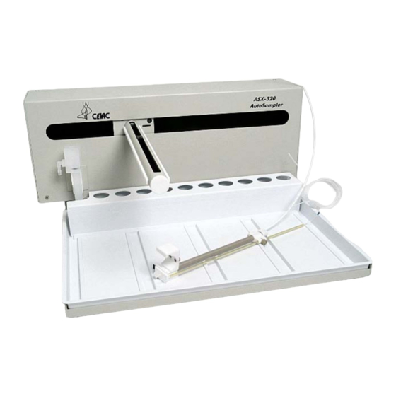
NOTE Your equipment may differ in appearance from what is shown in the photos. The photos show components which are intended to represent typical CETAC instruments from a range of eras. Most of the photos depict a standard ASX- 520; note that for the EXR-8, the standards rack is attached to autosampler and not integrated with the tray. - Page 8 / EXR-8 Installation Guide PRESS View of Y-axis home block with Kynar thumbscrews. Remove the entire Z-drive assembly from the Y-arm by pulling the Z-drive Figure 2-1 assembly forward and off of the autosampler arm as shown (Figure 2-2). Z-drive removed from arm assembly. (Photo shows Figure 2-2 standard ASX-520 tray with integral standards rack.)
- Page 9 / EXR-8 Installation Guide PRESS Chapter 2: Setting the Pump Speed Jumper Once the Z-drive assembly is removed, remove the rinse station (Figure 2-3). Turn the rinse station ¼ turn counter-clockwise while pulling it upward. Also, the tubing located at the bottom of rinse station will have to be disconnected from the pump at the rear of the autosampler.
- Page 10 / EXR-8 Installation Guide PRESS The autosampler tray should then be removed. Lift up the tray and pull out (Figure 2-5). Figure 2-5 Removing the tray (ASX-520) Next, the front cover is to be removed. Remove the four corner screws (Figure 2-6).
- Page 11 / EXR-8 Installation Guide PRESS Chapter 2: Setting the Pump Speed Jumper The front cover is removed by lifting it slightly and pulling forward (Figure 2-7). Figure 2-7 ASX-520 autosampler with the front cover being removed The screws that hold the inner shield must be removed. Move the Y-axis assembly all the way to the left (Figure 2-8 shows screw locations).
- Page 12 / EXR-8 Installation Guide PRESS The inner shield can be removed by moving the arm to the right or left then lifting it up while pulling forward.(Figure 2-9). Removal of inner shield (ASX-520) If you have a newer shield/splash guard combination proceed as follows. Figure 2-9 Locate and remove the 5 screws holding the shield in place.
- Page 13 / EXR-8 Installation Guide PRESS Chapter 2: Setting the Pump Speed Jumper Remove the two shield pieces. Notice that the splashguard goes under the chassis on the top and over the chassis on the bottom. When you replace the splashguard, ensure it is oriented in this manner. Figure 2-11 View of splashguard placement.
- Page 14 / EXR-8 Installation Guide PRESS Remove the splashguard by pulling it out from one side. It may be necessary to reach under the guard and remove it from the support standoffs. Figure 2-12 View of splashguard removal.
-
Page 15: Setting The Pump Speed Jumper (Asx-520/Asx-520Hs/Exr-8)
/ EXR-8 Installation Guide PRESS Chapter 2: Setting the Pump Speed Jumper Setting the Pump Speed Jumper (ASX-520/ASX- 520HS/EXR-8) Locate the block of pump speed pins on the left side of the main circuit board Move the jumper from its existing position to the position marked “Max RPM ” (Figure 2-13). - Page 16 / EXR-8 Installation Guide PRESS This page is intentionally blank.
-
Page 17: Install The Xpress Rinse Station And Rinse Tubing
If you have purchased a full system, it will already be configured properly PRESS and this step will not be necessary. If you are connecting the ASXpress Plus system to an autosampler with a standard rinse station installed, then you will need to replace it with the... -
Page 18: Removing The Existing Rinse Station
/ EXR-8 Installation Guide PRESS Xpress rinse station (supplied with the upgrade kit), and make the tubing modifications as described in this section. The Xpress rinse station is smaller than the one provided with the autosampler. This smaller rinse station allows the rinse solution to flow efficiently at the high flow rate used by the ASX system. -
Page 19: Installing The Rinse Tubing
/ EXR-8 Installation Guide PRESS Chapter 3: Installing the Rinse Plumbing Installing the Rinse Tubing An external peristaltic pump, which is faster than the one built into the autosampler, must be used to supply the rinse station. The pump will be powered by the ASX electronics module. - Page 20 / EXR-8 Installation Guide PRESS Rinse solution may be recycled by directing the waste tube into the rinse solution container, if appropriate for your application. Make sure that the end of the waste tube is above the surface of the liquid in the container. A short length of 1/4"...
- Page 21 / EXR-8 Installation Guide PRESS Chapter 3: Installing the Rinse Plumbing Rinse solution with air bubbles to rinse station Waste rinse solution Figure 3-5 Rinse tubing and communication cables Rinse solution with air bubbles to rinse station Waste rinse solution Cables Figure 3-6 Rinse tubing and communication cables Waste rinse solution...
-
Page 22: Install The 1.0Mm Id Sample Probe On The Autosampler
Install the 1.0mm ID Sample Probe on the Autosampler A 1.0mm ID sample probe (Figure 3-9) is provided for use with the CETAC autosampler for proper operation with the ASXpress P system. Follow the autosampler Operator Manual Instructions to replace the probe with the 1.0mm sample probe, which is attached to the ASX... -
Page 23: Press Plus System
4 Connecting the System PRESS To work properly with the ASX Rapid Sample Introduction System, the autosampler will require: PRESS Prepare and position the valve/pump PRESS PLUS module: Remove the protective cover from the 6-port valve. Attach the sample probe to port #2- grey. - Page 24 This may require adjusting vertical and horizontal placement of the valve/pump module, the orientation of the valve, or the orientation of the spray chamber. To accommodate additional placement convenience, the CETAC SP6572 Articulating Mounting System is available. Note: Minimize the tubing length between...
- Page 25 / EXR-8 Installation Guide PRESS Chapter 4: Connecting the ASXpress Plus System Position the ASX PRESS PLUS electronics module and connect it to the valve/pump module with the attached cable. Considerations: ● Place within 5 feet of the valve/pump module.
- Page 26 / EXR-8 Installation Guide PRESS Connect the autosampler’s serial input port to the AUTOSAMPLER port on the electronics module. (If PRESS PLUS the autosampler has more than one serial port, the input port is typically labeled “COM 1.”) Connect the GUI COM port on the electronics module to the host computer.
- Page 27 / EXR-8 Installation Guide PRESS Chapter 4: Connecting the ASXpress Plus System USB Connections Multiple communication cable options provide flexibility to use all RS-232, all USB or a combination of cables between the host PC and the electronics module. A USB driver must be installed to make the USB port emulate an RS-232 COM port, and the installation must be repeated for each USB connection.
- Page 28 / EXR-8 Installation Guide PRESS Connect the carrier/rinse solution: Prepare a carrier/rinse solution that is matrix-matched to your samples. A carrier/rinse solution bottle is provided with the ASX PRESS PLUS Connect the carrier/rinse tee assembly to two lengths of peristaltic pump tubing (customer supplied) and install at the ICP instrument’s peristaltic pump (see page 31).
- Page 29 / EXR-8 Installation Guide PRESS Chapter 4: Connecting the ASXpress Plus System Connect the opposite end (green fitting) of the carrier/rinse tee assembly to port #6-green of the 6-port valve (see PRESS PLUS photo at right and the diagram on page 31 of this guide).
- Page 30 To do so, follow the instructions found in the ASX PRESS PLUS Operator’s Manual, which is available on the CD or from www.cetac.com. Set the autosampler personality to match the analytical instrument you are using, if necessary. (See the Guide to Configuring Firmware Personalities which is provided on the included CD.)
-
Page 31: Valve/Pump Module Liquid Flow Connections
/ EXR-8 Installation Guide PRESS Chapter 4: Connecting the ASXpress Plus System Valve/Pump Module Liquid Flow Connections 6-Port Valve Liquid Flow Connections PRESS PLUS (6-port valve shown in the inject p... -
Page 32: Power/Communication General Connections
/ EXR-8 Installation Guide PRESS Power/Communication General PRESS PLUS Connections The external peristaltic pump (not shown) plugs into the EXTERNAL PUMP connector on the electronics module. The communication cables are pre- installed in the EXR-8 chain. Refer to the ASX Operator’s Manual for PRESS PLUS further instruction, as required. - Page 34 480176 Manual Part Number rev1 Printed in USA...
Need help?
Do you have a question about the ASXPRESS PLUS and is the answer not in the manual?
Questions and answers