
Subscribe to Our Youtube Channel
Related Manuals for CETAC ASX-500 Series


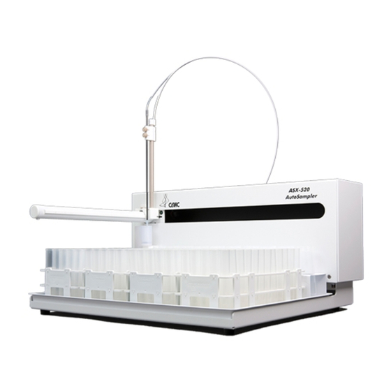
Summary of Contents for CETAC ASX-500 Series
- Page 1 Z-Drive Assembly for the CETAC ASX-500 Series Autosampler Platform (ASX-520/260/130/XLR-8) Quick Installation Guide Manual Part Number 610143 Rev 1, © 2012 CETAC Technologies, Printed in USA...
- Page 2 Overview This installation guide describes how to install the Z-drive assembly onto your autosampler. These instructions apply to CETAC ASX-500 series autosamplers, including Do these instructions apply to my autosampler? (but not limited to) the ASX-520, ASX-260, ASX-130 and XLR-8.
- Page 3 Figure 1. The autosampler is shipped with the Z-drive not attached. Remove the Z-drive assembly (Figure 2) from its packaging. Sleeve (Protects Z-Drive Cable) Sample Tube Z-Axis Slider PEEK Nut Sample Probe Y-Axis Slider Z-Drive Cable (Varies Depending on Version) Home flag Figure 2.
- Page 4 Slide the Z-drive assembly onto the autosampler arm. Figure 3. Sliding Z-drive on arm tube. Slide the Z-drive assembly onto the Y-axis leadscrew nut (the black block which moves back and forth along the arm). Lift the bushings with your fingernails to get them over the edge of the leadscrew nut.
- Page 5 Secure by tightening the thumbscrews. Figure 5. Tightening the thumbscrews. Feed the cable through the rear guide block, then tighten the PEEK nut to secure it (Figure 6). Figure 6. Tighten PEEK nut for cable casing adjustment.
- Page 6 Turn the rotor clockwise as far as it will go (Figure 7). Rotor Pin Stator Stop Figure 7. View of rotor with rotor pin at stator stop. Slide the cable onto the rotor on the back of the autosampler (Figure 8). Loosen the thumbscrew on the rotor to allow the cable to pass through the clamp (Figure 11).
- Page 7 Gently move the Z-axis slider until the gap between the slider and cap is approximately 3/32” (~2mm) (Figure 9). 3/32” (~2mm) Figure 9. View of gap between probe bracket and cap. Hold the cable flat against the rotor and secure the cable by tightening thumbscrew on the rotor (Figure 10).
- Page 8 Center the Y-arm tube in the autosampler X-travel slot in order to properly adjust the drive cable (Figure 12 and Figure 13). This step applies to all models of ASX-500 series autosamplers. X-travel slot Figure 12. Arm centered for cable casing adjustment.
- Page 9 Figure 13. Proper cable orientation. The Z-drive assembly is now properly installed on the autosampler.
Need help?
Do you have a question about the ASX-500 Series and is the answer not in the manual?
Questions and answers