Table of Contents
Advertisement
Advertisement
Table of Contents

Related Manuals for CETAC ASX-1400


Summary of Contents for CETAC ASX-1400
- Page 1 ASX-1400 Autosampler Operator’s Manual...
- Page 2 Product Warranty Statement SD Acqu isit ion , In c., DBA CE TAC Tech n ologies (“CE TAC”) wa r r a n t s a n y CE TAC u n it m a n u fa ct u r ed or su pplied by CE TAC for a per iod of t wen t y five (25) m on t h s fr om t h e da t e of sh ipm en t .
- Page 3 P u r ch a ser sh a ll in dem n ify CE TAC a ga in st a n y cla im or lia bilit y wh ich m a y be a sser t ed a s r ela t es t o t h e followin g: (i) t h e u se t o wh ich a n y pr odu ct su pplied h er eu n der is pu t in fr in ges t h e pa t en t , copyr igh t or ot h er in t ellect u a l pr oper t y r igh t s of a n y t h ir d pa r t y;...
- Page 4 Requests for additional copies of this, or any other CETAC publication, can be CAUTION and WARNING statements, as filled contacting authorized applied this...
- Page 5 Furthermore, never operate instrument without first reading and understanding the ASX-1400 Operator’s Manual and ensuring that it is operated safely and properly. ORIGINAL PACKAGING Retain original factory packaging for moves and factory return shipments.
- Page 6 The FCC requires the user to be notified that any changes or modifications made to this device that expressly approved by CETAC may void the user's authority to operate the equipment. CABLES Connections to this device must be made with shielded...
- Page 7 To reduce the risk of electrical shock, do not open the cabinet. All maintenance is to be performed by an Authorized CETAC Service Provider. Protection provided by the equipment may be impaired if the equipment is used in a manner not specified by the manufacturer.
- Page 8 Operator’s Manual Addendum Notices and Compliance Declarations PAN N EAU N E DOIT ÊTRE EN LEVE QUE PAR UN RÉPARATEUR QUALIFIÉ. AVERTISSEMEN T POUR UN E PROTECTION CON TIN UÉ CON TRE LES RISQUES D’IN CEN DIE, REMPLACER UN IQUEMEN T PAR DES FUSIBLES DE MÊME TYPE ET AMPÈRAGE.
- Page 9 Attention – Refer to the manual. This symbol indicates that information about usage of a feature is contained in the manual. WARNING If the autosampler is used in a manner not specified by CETAC Technologies, the protection provided the equipment may be impaired. AD-4...
- Page 10 Operator’s Manual Addendum Notices and Compliance Declarations WARNING The power switch on the rear panel is not the mains disconnect. Mains disconnect is accomplished by disconnecting the detachable power supply cord at the appliance coupler or at the mains plug. Ensure the power cord is easily accessible and removable, in the event of an emergency, which requires immediate disconnection.
- Page 11 NOTE: For instructions on how to return end-of-life equipment, producer-supplied electrical accessories, or auxiliary items for proper disposal please contact the supplier or importer. In the event a supplier cannot be reached, contact CETAC Technologies customer service department at 1 (800) 369 2822. AD-6...
- Page 12 Contents...
-
Page 13: Table Of Contents
Cautions Warnings Where to Go for More Information 1 Introduction 1–2 Autosampler Standard Components 1–2 Optional Accessories 1–6 2 Preparing for Installation 2–2 Choosing a Location 2–2 Space Requirements 2–2 Water Requirements 2–2 Power Requirements 2–3 Unpacking the ASX-1400 2–4... - Page 14 ASX-1400 Autosampler Operator’s Manual Contents 3 Installing the Autosampler 3–2 Mounting the Z-Drive Assembly 3–3 Attaching the Z-Drive Assembly to the Autosampler Arm 3–3 Attaching the Z-Drive Cable 3–5 Installing the Sample Probe 3–5 Removal of the Stirring Assembly 3–5 Connecting the Rinse Station 3–6...
- Page 15 ASX-1400 Autosampler Operator’s Manual Contents 4 Verifying Installation 4–2 Testing the Interface 4–2 Checking the Autosampler Components 4–6 Testing the Sample Probe 4–6 5 Using the Autosampler 5–2 Establishing Optimal Operating Conditions 5–2 Creating the Lab Environment 5–3 Replacing Autosampler Components 5–4...
- Page 16 ASX-1400 Autosampler Operator’s Manual Contents Replacing the Rinse Station Tubing 6–7 Replacing the Sample Tray 6–8 7 Troubleshooting the Autosampler 7–2 Power System Problems 7–2 Interface Problems 7–3 RS-232 Cable Problems 7–3 Software Configuration Problems 7–3 Z-Drive Assembly Problems 8 Appendix A 8–2...
-
Page 17: Preface
Preface... -
Page 18: Who Should Read This Book
Chapter 1, “Introduction,” provides you with an overview of the ASX- 1400 Autosampler’s function and design. Chapter 2, “Preparing for Installation,” discusses space and power requirements that must be met before the ASX-1400 is installed. It also provides instructions for unpacking the autosampler. -
Page 19: Conventions Used In This Book
ASX-1400 Autosampler Operator’s Manual Preface Chapter 3, “Installing the Autosampler,” provides step-by-step procedures for installing the ASX-1400 and connecting it to the analytical instrument. Chapter 4, “Verifying Installation,” explains how to test the communications interface between the ASX-1400 and the host computer. -
Page 20: Menu Items
ASX-1400 Autosampler Operator’s Manual Preface Menu Items This book uses the following format for referring to menu items: Settings Communication The text before the forward slash symbol is the name of the menu; the text after the forward slash symbol is the menu choice. This example refers to the Communications Menu choice in the Settings Menu. -
Page 21: Notes
ASX-1400 Autosampler Operator’s Manual Preface Y-Axis The front-to-back axis of the autosampler. Z-Axis The up-and-down axis of the autosampler. Notes Notes contain a reminder about the effect of particular actions. They are indicated as follows: Note: This example shows how a note is displayed. -
Page 22: Where To Go For More Information
ASX-1400 Autosampler Operator’s Manual Preface Where to Go for More Information In addition to the ASX-1400 Autosampler Operator’s Manual, you can refer to the following resources: • The software manual for the ICP-AES or ICP-MS instrument you are using •... -
Page 23: Introduction
Introduction... -
Page 24: Autosampler Standard Components
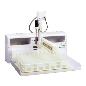
Introduction The ASX-1400 Autosampler is designed to be sturdy, reliable, and easy to use. It provides automated sample introduction that enables you to perform other tasks while the autosampler runs. The ASX-1400 automatically introduces up to 360 samples when fully loaded. - Page 25 • Solutions of concentrated acids (greater than 40%) • Solutions of concentrated bases (greater than 10% potassium, ammonium, or sodium hydroxides) • Partially halogenated hydrocarbons or extremely aggressive organic solvents (chloroform, methylene dichloride, 1,1,2-trichloroethane) Figure 1–1. ASX-1400 Autosampler—Front View. 1–3...
- Page 26 Hold four sets of the Bel-Art sample vial racks. You can choose from five different rack sizes (with either 21, 24, 40, 60 or 90 vials per rack). b) The ASX-1400 also can handle five sets of Gilson 60 position number 29 rack. c) Hold three of the APS-1650 80 position collection racks.
- Page 27 The pump moves the rinse solutions from the rinse source through the flowing rinse stations. Previous versions of the ASX-1400 shipped with two two-channel peristaltic pumps. One main pump and one auxiliary pump. If your unit uses the two pump setup, refer to Appendix A in this manual.
- Page 28 3) Optional 5-Channel Input/Output (I/O) Auxiliary Port. 4) USB Option. The ASX-1400 comes standard with a USB port. This port can be used to interface the ASX-1400 with the host computer. 5) Stirrer Speed Control. The control knob can either be set at a factory set speed or control the stirrer speed to optimize mixing of the sample.
-
Page 29: Optional Accessories
1400 to a host computer that uses a non-RS-232 communications protocol, you may need optional accessories in addition to the standard components included with the autosampler. The following accessories are available for the ASX-1400: • IEEE-488 Interface Kit. The kit includes an RS-232/IEEE-488 converter box, an IEEE-488 cable, a power cord, and instructions. - Page 30 No markings Note: Contact CETAC Technologies if you need additional accessories not listed, need added features to integrate the ASX-1400 Autosampler into your analytical system, or have unique requirements. Research and development of new features and accessories for the ASX-1400 Autosampler, often inspired by customer requests, is a continuing activity at CETAC Technologies.
-
Page 31: Preparing For Installation
Preparing for Installation... -
Page 32: Choosing A Location
ASX-1400 is 7l x 71 x 76 centimeters. Rinse Solution Requirements For most applications, deionized water or kerosene is used for rinse agent in the ASX-1400. If a different rinse agent is routinely used, place the rinse agent source within two meters of the ASX-1400. -
Page 33: Power Requirements
Power Requirements Place the ASX-1400 within 1.2 meters of a power outlet. The ASX-1400 uses an external desktop power supply. The input rating is AC 100V- 240V 3.2 A with an output of DC 28V, maximum 4.6 A. - Page 34 ASX-1400 Autosampler Operator’s Manual Preparing for Installation before opening and exposing to warm, humid air. It is usually sufficient to provide four to eight hours for this purpose. CAUTION If condensation forms on or inside the autosampler, allow it to dry thoroughly before connecting it to a power source and operating it.
-
Page 35: Installing The Autosampler
Installing the Autosampler... - Page 36 Installation consists of two parts: assembling the autosampler and connecting it to the host analytical instrument. The ASX-1400 can be installed with minimal effort. The only items that will be needed are a Ball Point Allen Wrench set, which is included in the ASX-1400 kit, and a screwdriver.
-
Page 37: Mounting The Z-Drive Assembly
ASX-1400 Autosampler Operator’s Manual Installing the Autosampler Shipping Fixture Process A shipping fixture is used to secure the Y-Arm during shipping. The Y shaped bracket must be removed before the unit is powered on. To remove the fixture, remove the screw securing the bracket, remove the bracket, and reattach the screw in the same location. - Page 38 ASX-1400 Autosampler Operator’s Manual Installing the Autosampler 3) Locate the two mounting pins on the assembly. 4) Place the pins in the corresponding holes in the mounting block, while holding it stable. 5) Insert the screws one at a time, while continuing to hold the assembly stable.
- Page 39 ASX-1400 Autosampler Operator’s Manual Installing the Autosampler Figure 3-2 Mounting of Z-Drive Assembly 3–5...
-
Page 40: Removal Of The Stirring Assembly
Do not unplug the Z-Drive cable with the unit powered on. Failure to do so will cause catastrophic damage to the ASX-1400. Installation and Removal of the Sample Probe 1) To remove the sample probe, loosen the thumbscrew and pull probe straight out. -
Page 41: Connecting The Rinse Station
2) Empty the drip cup, clean it and then return it to the cup holder. Single 3-Channel Peristaltic Pump Early versions of the ASX-1400 were shipped with dual peristaltic pumps. One on-board (main) 2-channel peristaltic pump, plus one Auxiliary 2-channel peristaltic pump. If your ASX-1400 contains dual peristaltic pumps, refer to Appendix A of this manual. -
Page 42: Pumped Drain Arrangement
ASX-1400 Autosampler Operator’s Manual Installing the Autosampler station. The waste rinse then drains from the rinse station by means of a pumped drain which is the standard arrangement for draining the rinse station. Pumped Drain Arrangement In a pumped drain arrangement, the rinse solution moves through the center channel of the on-board peristaltic pump to the inlet at the bottom of the rinse station. - Page 43 ASX-1400 Autosampler Operator’s Manual Installing the Autosampler Figure 3-2. Pumped Drain Arrangement 3–9...
- Page 44 ASX-1400 Autosampler Operator’s Manual Installing the Autosampler To connect the rinse station, complete the following steps: Note: Portions of the tubing assembly may have been completed in advance at the factory. 1) Connect the rinse solution to the on-board peristaltic pump...
- Page 45 ASX-1400 Autosampler Operator’s Manual Installing the Autosampler b) Connect the tubing to the drain (rinse out) channel of the rinse station. The drain (rinse out) channel is the side with a single reservoir, and is opposite of the security bracket.
-
Page 46: Changing The Rinse Pump Speed
Assembling and Placing the Sample Vial Racks Depending upon the version of the ASX-1400 Autosampler, the sample vial racks may come assembled and ready for use. Some versions of sample vial racks are shipped unassembled. However, you can easily assemble them without using tools. - Page 47 Ensure the rack is not tilted and is properly placed. 4) Repeat step three until you place all the sample vial racks. When viewed from the front of the ASX-1400, the sample vial racks should now be arranged on the sample tray as follows: Rack #1 at...
-
Page 48: Establishing External Connections
Connecting the ASX-1400 Autosampler to the Host Computer You cannot operate the ASX-1400 Autosampler until you establish a communications interface between the autosampler and the host computer. It is through this interface that the host computer directs the... -
Page 49: Establishing A Serial Communications Interface
The serial (RS-232) protocol is the standard configuration. There are two RS-232 serial ports on the ASX-1400, and a serial interface kit is shipped with the autosampler. The parallel (IEEE-488) protocol is less common than the serial ... -
Page 50: Establishing An Ieee Communications Interface
CETAC Technologies or purchase an adapter locally to convert the serial port to DB9M. No not use a “null modem” adapter. 3) Connect the other end of the cable to the ASX-1400 COM1 port. Ensure you are connecting the adapter to the COM1 port. Connecting... -
Page 51: Establishing A Usb Communications Interface
2) Plug one end of the cable into the serial port on the 232-488 converter box. 3) Finger-tighten both screws of the cable adapter. 4) Connect the other end of the cable to the ASX-1400 COM1 port. Ensure you are connecting the adapter to the COM1 port. Connecting... -
Page 52: Verifying Installation
Verifying Installation... -
Page 53: Testing The Interface
ASX-1400 Autosampler Operator’s Manual Verifying Installation Verifying Installation Once installation of the ASX-1400 Autosampler is complete, it is important to verify that you have installed it correctly. Attempting to use it before ensuring that it is installed correctly may result in damage to the autosampler. - Page 54 ASX-1400 Autosampler Operator’s Manual Verifying Installation Note: The following procedures assume that you started the Windows operating system and the Program Manager window is showing. To test the communications interface, complete the following steps: 1) Start the host computer and go to the main Windows screen.
- Page 55 ASX-1400 Autosampler Operator’s Manual Verifying Installation 5) Double click on the Hyperterminal icon. ® a) The Connection Description box appears (Figure 4–2). Figure 4–2. Connection Description Box. 6) Type the name COM1_test for the connection and choose an icon from the list given, and click OK.
- Page 56 ASX-1400 Autosampler Operator’s Manual Verifying Installation Figure 4-3. Phone Number Box. 7) Select Direct to COM1 in the Connect Using box. Click OK. The COM1 Properties box appears (Figure 4-4). Figure 4-4. COM1 Properties Box. 4–5...
- Page 57 ASX-1400 Autosampler Operator’s Manual Verifying Installation 8) Change the bits per second to 9600, set the data bits to eight, the parity to none, the stop bits to one, the flow control to none, and click OK. 9) Select File/Properties.
-
Page 58: Checking The Autosampler Components
ASX-1400 Autosampler Operator’s Manual Verifying Installation 12) Click OK on the COM1_Test Properties box. 13) Type HOME at the cursor in the upper left of the main Hyperterminal screen and press Enter. ® The autosampler resets, with the sample probe moving out and back into the home position. - Page 59 ASX-1400 Autosampler Operator’s Manual Verifying Installation Note: Before testing the sample probe, ensure that you have installed all autosampler components correctly. Also, ensure that you have securely tightened all thumbscrews and connected the communications cable from the host computer to the COM1 port on the autosampler.
-
Page 60: Using The Autosampler
Using the Autosampler... -
Page 61: Establishing Optimal Operating Conditions
ASX-1400 Autosampler Operator’s Manual Using the Autosampler Using the Autosampler The ASX-1400 Autosampler is both reliable and easy to use. Before using it, however, ensure that your lab environment provides operating conditions that will prolong the life of the ASX-1400 Autosampler. Once the proper operating conditions are met, you can arrange the sample vial racks and start the autosampler sequence run. -
Page 62: Creating The Lab Environment
20–70% non-condensing, and the unit is not exposed to excessive flammable or corrosive materials. • Avoid rough handling of the ASX-1400 Autosampler. If possible, do not expose the autosampler to vibration or shock. • Protect the autosampler from long-term exposure to condensation, corrosive materials, solvent vapor, continual standing liquids, or large spills into the autosampler cabinet or arm. -
Page 63: Replacing Autosampler Components
ASX-1400 Autosampler Operator’s Manual Using the Autosampler Replacing Auto Sampler Components The following ASX-1400 Autosampler components wear out under normal use and must be replaced periodically. • Peristaltic pump tubing • Sample probe If you fail to replace these components when they deteriorate, the autosampler will not function properly. -
Page 64: Arranging The Sample Vial Racks
Use of mismatched sample vials and sample vial racks may result in malfunctions or sample spills. Be sure your vials meet the given requirements. To order additional supplies, refer to the CETAC Accessories and Supplies Catalog for the ASX-1400 Autosampler. Arranging the Sample Vial Racks You can change the arrangement of the sample vial racks to meet your needs. - Page 65 Flush the rinse system a second time using deionized water as the rinse agent. 5) Access the host computer’s software and activate the autosampler program. The ASX-1400 Autosampler runs until it reaches the end of the sampling sequence. 5–6...
-
Page 66: Shutting Down The Autosampler
After the use of strong bases, acids, or organic solvents as rinse agents. Flushing the rinse system during initial startup of the ASX-1400 Autosampler removes any contaminants that could cause interference during sample analysis. Flushing the rinse system after using strong... - Page 67 ASX-1400 Autosampler Operator’s Manual Using the Autosampler rinse agents prevents degradation and failure of the flow path components. To flush the rinse station and flow path, complete the following steps: 1) Insert the rinse uptake tubing into a deionized water source.
-
Page 68: Maintaining The Autosampler
Maintaining the Autosampler... -
Page 69: Cleaning The Autosampler
Failure to do so regularly causes increased wear and reduces the autosampler’s life. You must clean the ASX-1400 Autosampler both daily and weekly to prevent damage and extend its life. It is especially important to clean up spills and remove contaminants, such as abrasives, from the autosampler’s moving parts. -
Page 70: Daily External Cleaning
Daily External Cleaning Use of the ASX-1400 Autosampler often results in spills on autosampler components such as the sample tray. Good maintenance requires that you clean the autosampler daily. To do so, complete the following steps: 1) Shut down and unplug the autosampler. - Page 71 1) Shut down and unplug the autosampler. 2) Remove the sample tray. For information about removing the sample tray, see ‘‘Replacing the Sample Tray’’ later in this chapter. 3) Wipe loose particles off the Y-Axis lead screw with a dry, lint-free cloth.
-
Page 72: Checking For Leaks
Never lubricate the lead screws. The lead screw nuts are WARNING compounded with a dry film lubricant. Oiling the lead screws will cause gumming, galling, and binding of the sample probe assembly. 4) Wipe the Autosampler exterior and base until they are clean, using a towel dampened with a lab-grade cleaning agent, followed by a towel dampened with clear water. -
Page 73: Replacing Peristaltic Pump Tubing
For more information, see the appropriate section in this chapter. Replacing Peristaltic Pump Tubing Routine maintenance ASX-1400 Autosampler includes replacement of the peristaltic pump tubing. Because of the operating nature of peristaltic pumps, the tubing will probably be the most frequently replaced item on the autosampler. -
Page 74: Replacing The Rinse Station Tubing
2) Remove the old sample probe and tubing. Be careful not to use excessive force when removing the sample probe. Applying too much force can result in damage to the Z-Drive assembly. 3) Install the new sample probe. For information about installing the sample probe, see Chapter 3, “Installing the Autosampler.”... - Page 75 5) Replace the rinse station tube by pushing the new rinse station tube into the mounting block and rotating it clockwise 1/4 turn. 4) Reconnect the rinse solution uptake and drain tubing. Apply only a linear force when replacing the tubing to prevent the fittings from breaking.
-
Page 76: Troubleshooting The Autosampler
Troubleshooting the Autosampler... -
Page 77: Power System Problems
RS-232 cable, or the autosampler. If you determine the problem is in the ASX-1400, check the power system, the communications interface, or the sample probe assembly to find the cause of the problem and resolve it. -
Page 78: Software Configuration Problems
ASX-1400 Autosampler Operator’s Manual Troubleshooting the Autosampler host computer. The following sections explain how to troubleshoot these problems. RS-232 Cable Problems The first step in troubleshooting interface problems is to check the RS-232 cable. To do so, complete the following steps: 1) Check the autosampler power switch to ensure it is on. -
Page 79: Z-Drive Assembly Problems
Z-Drive assembly. You can easily determine that a malfunction is related to the Z-Drive assembly if you hear a loud chattering noise when the ASX-1400 power switch is on or if the sample probe is not moving. To troubleshoot Z-Drive assembly problems, complete the following... - Page 80 ASX-1400 Autosampler Operator’s Manual Troubleshooting the Autosampler Figure 7–1. Z-Drive Assembly with Y-Axis Block Home Position Flag. 7–5...
- Page 81 Appendix A...
-
Page 82: Dual 2-Channel Peristaltic Pump
Dual 2-Channel Peristalic Pumps Early versions of the ASX-1400 were shipped with dual peristaltic pumps. One on-board (main) 2-channel peristaltic pump, plus one Auxiliary 2-channel peristaltic pump. If your ASX-1400 contains dual peristaltic pumps, refer to these instructions. If your ASX-1400 contains a single 3-channel peristaltic pump, refer to the instructions starting on 3-6. -
Page 83: Connecting The Rinse Station
, or a solution from the kerosene family, are used as the rinse solution and is pumped into the rinse station by the on-board peristaltic pumps. There are two pumps on the ASX-1400 Autosampler; one is used to supply rinse solution to the rinse station for the stirring paddle and sample probe, while other is used to pull rinse solution from the rinse station. - Page 84 ASX-1400 Autosampler Operator’s Manual Installing the Autosampler The first step is to install the auxiliary pump on the back of the autosampler. The auxiliary pump attached to the back of the instrument above the other pump. There are holes keyed onto the back of the pump and correspond with the plastic pieces attached to the instrument.
- Page 85 ASX-1400 Autosampler Operator’s Manual Installing the Autosampler 1) Connect the rinse solution to the main on-board peristaltic pump by inserting the 3mm (milimeter) i.d. Tygon tubing ® onto the inlet at the top of the pump. Use the tubing for the rinse solution uptake.
- Page 86 ASX-1400 Autosampler Operator’s Manual Installing the Autosampler Again, insert the tubing carefully to avoid breaking the fitting. 4) Connect the both channels of the auxiliary on-board peristaltic pump to the rinse solution waste container by completing the following steps. Use two pieces of up to 1.8 meters of the tubing provided for the pumped drain.
-
Page 87: Gravity Drain Arrangement
ASX-1400 Autosampler Operator’s Manual Installing the Autosampler Gravity Drain Arrangement Figure 3-3. Gravity Drain Arrangement In a gravity drain arrangement, the rinse solution moves through the main peristaltic pump to the inlet at the bottom of the rise station, as shown in Figure 3-3. - Page 88 ASX-1400 Autosampler Operator’s Manual Installing the Autosampler a) Using both pieces of tubing place one end of the 3mm i.d. Tygon tubing onto the outlets at the bottom of the main ® pump. Insert the tubing carefully because the peristaltic pump fitting grips the tubing tightly.
-
Page 89: Changing The Rinse Pump Speed
ASX-1400 Autosampler Operator’s Manual Installing the Autosampler Changing the Rinse Pump Speed There are black knobs located on the rear of the unit that control the speed of the pumps. One knob controls the stirrer, and the other two control the pumps. If you turn the knobs all the way to the left (counter- clockwise), you will hear a click.
Need help?
Do you have a question about the ASX-1400 and is the answer not in the manual?
Questions and answers