Table of Contents
Advertisement
Quick Links
Advertisement
Table of Contents

Related Manuals for Aaeon ATX-Q670A


Summary of Contents for Aaeon ATX-Q670A
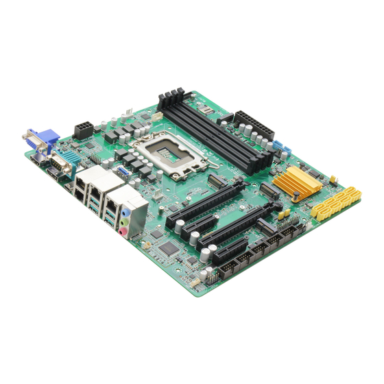
- Page 1 ATX-Q670A...
- Page 2 E21170 First Edition September 2022 Copyright Notice This document is copyrighted, 2022. All rights are reserved. The original manufacturer reserves the right to make improvements to the products described in this manual at any time without notice. No part of this manual may be reproduced, copied, translated, or transmitted in any form or by any means without the prior written permission of the original manufacturer.
-
Page 3: Table Of Contents
Contents Chapter 1 Product overview Package contents ................. 1-1 Features ..................1-1 1.3 Specifications ................1-2 Chapter 2 Motherboard information Before you proceed ..............2-1 Motherboard layout ..............2-2 Screw size ..................2-4 2.3.1 Component side .............. 2-4 2.3.2 Solder side ..............2-5 Central Processing Unit (CPU) ........... - Page 4 Contents 3.3.8 AMT Configuration ............3-10 3.3.9 PCH-FW Configuration ..........3-10 3.3.10 NVMe Configuration ............3-11 3.3.11 Power Management ............3-11 3.3.12 Digital IO Port Configuration ......... 3-11 Chipset menu ................3-12 3.4.1 System Agent (SA) Configuration ......... 3-12 3.4.2 PCH-IO Configuration ........... 3-12 Security menu ................3-12 3.5.1 Administrator Password ..........3-12 3.5.2 User Password ..............
-
Page 5: Chapter 1 Product Overview
Chapter 1 Product overview Package contents Check your industrial motherboard package for the following items. 1 x Industrial Motherboard 1 x SATA Cable 1 x I/O Shield 1 x VGA cable If any of the above items is damaged or missing, contact your distributor or sales representative immediately. -
Page 6: Specifications
12” x 9.6” (305 mm x 244 mm) Gross weight 1.76 lb (0.8 Kg) Operating 32°F~140°F (0°C~60°C) temperature Storage temperature -40°F ~185°F (-40°C ~85°C) Operating humidity 0%~90% relative humidity, non-condensing Power compliance Certificate CE/FCC Class A (continued on the next page) ATX-Q670A... - Page 7 DISPLAY Chipset Intel Graphics Media Accelerator ® DisplayPort Up to 4096 x 2160 @ 24 Hz / 3840 x 2160 @ 60 Hz, with Digital Audio (4k) HDMI ® Up to 4096 x 2160 @ 60 / 30 Hz, with digital audio (HDMI2.0) Up to 1920 x 1200 @ 60 Hz (via IT6516B) Internal I/O Storage...
- Page 8 ATX-Q670A...
-
Page 9: Chapter 2 Motherboard Information
Chapter 2 Motherboard information Before you proceed Take note of the following precautions before you install motherboard components or change any motherboard settings. CAUTION! • Unplug the power cord from the wall socket before touching any component. • Before handling components, use a grounded wrist strap or touch a safely grounded object or a metal object, such as the power supply case, to avoid damaging them due to static electricity. -
Page 10: Motherboard Layout
USB5 Place this side LGA1700 towards the rear LAN2_USB30_34 of the chassis LAN1_USB31_12 CHA_FAN1 AUDIO1 2280 Intel ® I225LM PCIEX16_1 Intel ® I210AT ATX-Q670A 256Mb PCIEX1 BIOS Intel ® Intel ® Q670E I219LM SPI_1 3052 2242 3042 PCIEX4 SIM2 SATA6G_2... - Page 11 Connectors/Jumpers/Slots Page VGA header 2-21 CPU and Chassis Fan headers (4-pin CPU_FAN, 4-pin CHA_FAN1~3) 2-20 ATX Power connectors (24-pin EATX_PWR1, 8-pin EATX_PWR2) 2-19 Intel LGA1700 CPU socket ® DDR5 DIMM slots 2-11 Micro SIM card sockets 2-27 Mini PCIe slot 2-26 Serial ATA 6.0Gb/s ports (7-pin SATA6G_0~7) 2-23...
-
Page 12: Screw Size
219.46 212.22 211.40 211.94 203.07 201.55 179.83 178.47 174.61 159.00 148.08 142.11 134.75 129.02 124.97 122.67 104.01 83.06 76.78 61.60 62.10 50.88 40.75 45.45 29.37 41.28 41.15 24.53 20.08 16.75 16.68 20.73 13.69 18.88 10.91 10.49 7.06 0.00 35.52 ATX-Q670A... -
Page 13: Solder Side
2.3.2 Solder side 237.49 237.49 211.80 201.45 188.47 165.10 165.10 161.67 158.21 142.67 140.67 104.67 102.67 95.15 85.15 83.67 51.42 33.02 10.16 0.00 0.00 Chapter 2: Motherboard information... -
Page 14: Central Processing Unit (Cpu)
Return Merchandise Authorization (RMA) requests only if the motherboard comes with the cap on the LGA1700 socket. • The product warranty does not cover damage to the socket contacts resulting from incorrect CPU installation/removal, or misplacement/loss/ incorrect removal of the PnP cap. ATX-Q670A... -
Page 15: Installing The Cpu
2.4.1 Installing the CPU • Ensure that you install the correct CPU designed for LGA1700 socket only. DO NOT install a CPU designed for LGA1155, LGA1156, LGA1151, and LGA1200 sockets on the LGA1700 socket. • ASUS will not cover damages resulting from incorrect CPU installation/ removal, incorrect CPU orientation/placement, or other damages resulting from negligence by the user. - Page 16 ATX-Q670A...
-
Page 17: Cpu Heatsink And Fan Assembly Installation
2.4.2 CPU heatsink and fan assembly installation Apply Thermal Interface Material to the CPU cooling system and CPU before you install the cooling system, if necessary. Ensure to remove the CPU Socket lever protector on the lever latch before installing the cooling system, failure to do so may cause damages to your system. - Page 18 To uninstall the CPU heatsink and fan assembly ATX-Q670A 2-10...
-
Page 19: System Memory
System memory The motherboard comes with Dual Inline Memory Modules (DIMM) slots designed for DDR5 (Double Data Rate 5) memory modules. A DDR5 memory module is notched differently from a DDR, DDR2, DDR3, or DDR4 module. DO NOT install a DDR, DDR2, DDR3, or DDR4 memory module to the DDR5 slot. -
Page 20: Installing A Dimm
2.5.1 Installing a DIMM To remove a DIMM ATX-Q670A 2-12... -
Page 21: Jumpers
Jumpers Clear RTC RAM (CLRTC) This jumper allows you to clear the Real Time Clock (RTC) RAM in CMOS. You can clear the CMOS memory of date, time, and system setup parameters by erasing the CMOS RTC RAM data. The onboard button cell battery powers the RAM data in CMOS, which include system setup information such as system passwords. - Page 22 AT/ATX Mode selection jumper (2-pin ATX_AT) ATX_AT ATX mode AT mode (Default) Pins 1-2 (Default) ATX mode AT mode NOTE: Jumper setting of ATX_AT should be consistent with the setting of Power Mode in BIOS. Refer to section 3.3.11 Power Management in Chapter ATX-Q670A 2-14...
- Page 23 Chassis intrusion header (4-1 pin CHASSIS) This header is for a chassis-mounted intrusion detection sensor or switch. Connect one end of the chassis intrusion sensor or switch cable to this header. The chassis intrusion sensor or switch sends a high-level signal to this header when a chassis component is removed or replaced.
- Page 24 Intel ME Jumper (3-pin DIS_ME) ® This jumper allows you to force the Intel Management Engine (ME) to boot ® from recovery mode when ME becomes corrupted. ATX-Q670A 2-16...
-
Page 25: Connectors
Connectors 2.7.1 Rear panel connectors Serial port (COM). This port connects a modem or other device that conforms with serial specification. LAN3 (RJ-45) port. This port allows Gigabit connection to a Local Area Network (LAN) through a network hub. Refer to the table below for the LAN port LED indications. - Page 26 We strongly recommend that you connect your devices to ports with matching data transfer rate. For example connecting your USB 3.2 Gen 1 devices to USB 3.2 Gen 1 ports for faster and better performance for your devices. 11. Microphone port (pink). This port connects to a microphone. ATX-Q670A 2-18...
-
Page 27: Internal Connectors
2.7.2 Internal connectors ATX Power connectors (24-pin EATX_PWR1, 8-pin EATX_PWR2) These connectors are for ATX power supply plugs. The power supply plugs are designed to fit these connectors in only one orientation. Find the proper orientation and push down firmly until the connectors completely fit. EATX_PWR2 EATX_PWR1 +3 Volts... - Page 28 CHA_FAN2 CAUTION: Do not forget to connect the fan cables to the fan headers. Insufficient air flow inside the system may damage the motherboard components. These are not jumpers! Do not place jumper caps on the fan headers! ATX-Q670A 2-20...
- Page 29 Audio Amplfier connector (4-pin AMP_CON2) This connector is for an internal stereo amplifier speakers support (2W/4 via WtoB header). AMP_CON2 PIN 1 VGA header The VGA header allows you to connect a display for BMC Remote Management. PIN 1 Chapter 2: Motherboard information 2-21...
- Page 30 (depending on the operating system settings). • Reset button header (2-pin RESET) The 2-pin header allows you to connect the chassis-mounted reset button. Press the reset button to reboot the system. ATX-Q670A 2-22...
- Page 31 Serial ATA 6.0Gb/s ports (7-pin SATA6G_0~7) These ports connect to Serial ATA 6.0 Gb/s hard disk drives via Serial ATA 6.0 Gb/s signal cables. RSATA_TXP RSATA_TXN SATA6G_0 RSATA_RXN SATA6G_1 RSATA_RXP SATA6G_2 SATA6G_3 SATA6G_4 SATA6G_5 SATA6G_6 SATA6G_7 NOTE: When using hot-plug and NCQ, set the SATA VMD controller item in the BIOS to [Disabled].
- Page 32 The plugged USB 3.0 device will run on xHCI mode. 10. USB 2.0 connector/header (10-1pin USB5, USB67) The USB connector/header comply with USB 2.0 specifications. USB5 USB67 PIN 1 Never connect a 1394 cable to the USB connector/header. Doing so will damage the motherboard. ATX-Q670A 2-24...
- Page 33 11. Serial Port headers (10-1 pin COM2~COM6) These headers are for serial (COM) ports. Connect the serial port module cable to this header, then install the module to a slot opening at the back of the system chassis. COM2 COM5 PIN 1 PIN 1 COM3...
- Page 34 This header includes 8 I/O lines (In/Out programmable). All of the Digital I/O lines are programmable and each I/O pin can be individually programmed to support various devices. PIN 1 13. Mini PCIe slot This slot allows you to install a mini PCIe module into your motherboard. MINI_CARD1 ATX-Q670A 2-26...
- Page 35 14. M.2 M-key / B-Key slots The M.2 M-key slots allow you to install M.2 (SATA or NVMe) SSD modules. The M.2 B-key slot allows you to install an M.2 SSD module. M2_TYPE_M1 M2_TYPE_B1 M2_TYPE_M1 NOTES: • The M.2 module is purchased separately. •...
- Page 36 The illustration below shows the location of the onboard LEDs. LED_5V Standby Power Powered Off LED_5VSB Main Power Main Power Off System state LED indication S0 state LED_5V & LED_5VSB keep lighting S5 state Only LED_5VSB keep lighting ATX-Q670A 2-28...
-
Page 37: Chapter 3 Bios Setup
Chapter 3 BIOS setup BIOS setup program Use the BIOS Setup program to configure its parameters. The BIOS screens include navigation keys and brief online help to guide you in using the BIOS Setup program. Entering BIOS Setup at startup To enter BIOS Setup at startup: Press <Delete>... -
Page 38: Bios Menu Screen
The Main menu provides you an overview of the basic system information, and allows you to set the system date, time, language, and security settings. 3.2.1 System Date [Day MM/DD/YYYY] Allows you to set the system date. 3.2.2 System Time [HH:MM:SS] Allows you to set the system time. ATX-Q670A... -
Page 39: Advanced Menu
Advanced menu The Advanced menu items allow you to change the settings for the CPU and other system devices. Be cautious when changing the settings of the Advanced menu items. Incorrect field values can cause the system to malfunction. Case Open Warning [Disabled] Allows you to enable or disable the case open detecting function. - Page 40 Selects to tell operating system to support PPI S pec Version 1.2 or 1.3. Some HCK tests might not support 1.3. Configuration options: [1.2] [1.3] Device Select [Auto] Allows you to select the TPM device. Configuration options: [Auto] [TPM1.2] [TPM2.0] ATX-Q670A...
-
Page 41: Ptt Configuration
3.3.3 PTT Configuration This item allows you to set the PTT configuration. TPM Device Selection [dTPM] Allows you to select TPM device. [PTT] Enables PTT in SkuMgr. [dTPM] Disables PTT in SkuMgr. When PTT is disabled, all data saved on it will be lost. 3.3.4 SATA Configuration The BIOS automatically detects the presence of SATA devices. -
Page 42: Usb Configuration
The following items appear only when you set Fan Control Mode to [Thermal Cruise Mode]. Critical temperature [60] Input value range: [0~255] Enable critical duty [Disabled] Configuration options: [Disabled] [Enabled] Critical duty value [10] Input value range: [0~127] Fan target temperature [40] Input value range: [0~127] ATX-Q670A... - Page 43 Tolerance value [0] Input value range: [0~7] Stop duty [Disabled] Configuration options: [Disabled] [Enabled] Stop value [10] Input value range: [0~127] Startup value [1] Input value range: [0~127] Stop time [60] Input value range: [0~127] The following items appear only when you set Fan Mode to [Speed Cruise]. Fan step up value [1] Input value range: [0~15] Fan step down value [1]...
-
Page 44: Sio Configuration
The items in this menu allow you to configure Super IO settings. [*Active*] Serial Port 1 Use this device [Enabled] Allows you to enable or disable this logical device. Configuration options: [Enabled] [Disabled] The following two items appear only when you set Use this device to [Enabled]. ATX-Q670A... - Page 45 Possible [Use Automatic Settings] Allows you to select an optimal setting for Super I/O devices. Configuration options: [Use Automatic Settings] [IO=3F8h; IRQ=4;] [IO=2F8h; IRQ=3] Mode [RS232] Allows you to select the Serial Port mode. Configuration options: [RS232] [RS422] [RS485] [*Active*] Serial Port 2 Use this device [Enabled] Allows you to enable or disable this logical device.
-
Page 46: Amt Configuration
Firmware Update Configuration Me FW Image Re-Flash [Disabled] Allows you to enable or disable Me firmware Image Re-Flash function. Configuration options: [Disabled] [Enabled] FW Update [Disabled] Allows you to enable or disable ME FW Update function. Configuration options: [Disabled] [Enabled] ATX-Q670A 3-10... -
Page 47: Nvme Configuration
3.3.10 NVMe Configuration The NVMe Configuration menu displays the NVMe controller and drive information of the devices connected and allows you to configure NVMe device options settings. 3.3.11 Power Management Power Mode [ATX Type] Select power supply mode. Configuration options: [ATX Type] [AT Type] The following items appear when you set Power Mode to [ATX Type]. -
Page 48: Chipset Menu
If you have set an administrator password, we recommend that you enter the administrator password for accessing the system. Otherwise, you might be able to see or change only selected fields in the BIOS setup program. To set an administrator password: Select the Administrator Password item and press <Enter>. ATX-Q670A 3-12... -
Page 49: User Password
From the Create New Password box, key in a password, then press <Enter>. Confirm the password when prompted. To change an administrator password: Select the Administrator Password item and press <Enter>. From the Enter Current Password box, key in the current password, then press <Enter>. -
Page 50: Secure Boot
Allows you to enroll SHA256 Hash certificate of a PE image into Authorized Signature database (db). Boot menu The Boot menu items allow you to change the system boot options. 3.6.1 Boot Configuration Quiet Boot [Enabled] This item enables/disables Quiet Boot. Configuration options: [Disabled] [Enabled] ATX-Q670A 3-14... -
Page 51: Fixed Boot Order Priorities
Network Stack [Disabled] This item allows user to disable or enable the UEFI network stack. Configuration options: [Disabled] [Enabled] 3.6.2 FIXED BOOT ORDER Priorities Boot Option #1~#10 This item allows you to set the system boot order. Configuration options: [USB Key] [USB Hard Disk] [Hard Disk] [NVME] [Network] [USB Lan] [CD/DVD] [USB CD/DVD] [USB Floppy] [SD] [Disabled] Save &... -
Page 52: Appendix
Check local regulations for disposal of electronic products. DO NOT throw the mercury-containing button cell battery in municipal waste. This symbol of the crossed out wheeled bin indicates that the battery should not be placed in municipal waste. ATX-Q670A... - Page 53 印 刷 電 路 板 及 其 × ○ ○ ○ ○ ○ 電子組件 外 部 信 號 連 接 頭 × ○ ○ ○ ○ ○ 及線材 ○: 表示該有毒有害物質在該部件所有均質材料中的含量均在 SJ/T 11363- 2006 標准規定的限量要求以下。 ×: 表示該有毒有害物質至少在該部件的某一均質材料中的含量超出 SJ/T 11363-2006 標准規定的限量要求,然該部件仍符合歐盟指令 2002/95/ EC 的規范。 備註:此產品所標示之環保使用期限,係指在一般正常使用狀況下。 ATX-Q670A...
Need help?
Do you have a question about the ATX-Q670A and is the answer not in the manual?
Questions and answers