
Subscribe to Our Youtube Channel
Related Manuals for Aaeon PCM-5896


Summary of Contents for Aaeon PCM-5896
- Page 1 PCM-5896 All-in-One Super7 Single Board Computer with LCD, Ethernet, Audio, & 4 COMs...
-
Page 2: Fcc Statement
FCC STATEMENT THIS DEVICE COMPLIES WITH PART 15 FCC RULES. OPERATION IS SUBJECT TO THE FOLLOWING TWO CONDITIONS: (1) THIS DEVICE MAY NOT CAUSE HARM- FUL INTERFERENCE. (2) THIS DEVICE MUST ACCEPT ANY INTERFERENCE RECEIVED INCLUDING INTERFERENCE THAT MAY CAUSE UNDESIRED OPERATION. THIS EQUIPMENT HAS BEEN TESTED AND FOUND TO COMPLY WITH THE LIMITS FOR A CLASS "A"... -
Page 3: Copyright Notice
SiS is a trademark of Silicon Integrated Systems Corp. VIA is a trademark of VIA Technology, Inc. All other product names or trademarks are properties of their respective owners. Part No. 2047589606 Manual PCM-5896 7th Edition Prepared in Taiwan June 2000... -
Page 4: Technical Support
Our dealers are well trained and ready to give you the support you need to get the most from your AAEON products. In fact, most problems reported are minor and are able to be easily solved over the phone. -
Page 5: Product Warranty
Because of AAEON’s high quality-control standards and rigorous testing, most of our customers never need to use our repair service. If an AAEON product is defective, it will be repaired or replaced at no charge during the warranty period. For out-of-warranty repairs, you will be billed according to the cost of replacement materials, service time, and freight. -
Page 6: Packing List
— VGA drivers and utilities — Audio drivers and utilities — Lastest BIOS (as of the CD-ROM was made) The PCM-5896 requires several cables for operation. You can make them yourself or pruchase an optioanl cable kit, PCM-10489-4 (P/N : 9979048910). - Page 7 Dear Customer, Thank you for purchasing the PCM-5896 board. This user’s manual is designed to help you to get the most out of the PCM-5896, please read it thoroughly before you install and use the board. The product that you have purchased comes with an two-year limited warranty, but AAEON will not be responsible for misuse of the product.
-
Page 8: Table Of Contents
Contents Chapter 1: General Information.......1 Introduction ..............2 Features ................... 3 Specifications ................4 Board layout ................7 Board dimensions ..............8 Chapter 2: Installaion .......... 9 Jumpers and connectors ............10 Locating jumpers (Component Side) ........12 Locatting jumpers (Solder Side) ......... 13 Locating connectors ............. - Page 9 IDE hard drive connector (CN5) ......... 29 IDE hard drive connector (CN5) ..........30 Front panel connector (CN6) ..........31 IrDA connector (CN7) ............32 Display connectors (CN9, CN12) ........33 VGA display connector (CN12) ..........33 LCD connector (CN9) ............34 CD Audio connector (CN10) ..........
- Page 10 PNP/PCI configuration setup ..........69 Load BIOS defaults/Load setup defaults ......72 Load setup defaults .............. 73 Integrated peripherals setup ..........74 Supervisor/User password setting ........77 IDE HDD auto detection ............79 Save & exit setup ..............80 Exit without saving ............... 81 Chapter 4: C&T 69000 Flat Panel/CRT controller Display Drivers and Utilities ..
- Page 11 Appendix A: Programming the Watchdog Timer Programming the watchdog timer ........108 How to set the watchdog timer ..........108 Demo Program ..............109 Appendix B: Installing PC/104 Modules ... 111 Installing PC/104 modules ..........112 Appendix c: Optional Extras ......115 PCM-10489-4 Wiring Kit ............
-
Page 13: Chapter 1: General Information
General Information This chapter gives background informa- tion on the mainboard. Sections include: • Board specifications • Layout and dimensions Chapter 1 General Information... -
Page 14: Introduction
EMI. Highly integrated multi-media SBC The PCM-5896 is a highly integrated multi-media SBC that com- bines audio, video, and network functions on a CD-ROM drive size single computer board. It provides 32-bit half-duplex, 16-bit full- duplex, PCI 3D audio and up to 1024 x 768 resolution @ 64K colors with on-chip 2MB SDRAM display memory. -
Page 15: Features
Features • Supports Intel P54C/P55C/Tillamook, AMD K6-2/K6, Cyrix 6x86MX/M II, and IDT Winchip (With system bus frequencies up to 100MHz) • DiskOnChip (SSD) up to 144MB • 64-bit PCI-bus SVGA/LCD controller supports LCD & CRT display • 100Base-Tx Ethernet interface, supports Remote Boot ROM function. •... -
Page 16: Specifications
• Battery: Lithium battery for data retention of up to 10 years (under normal condition) • Watchdog Timer: Can generate a system reset, IRQ15, or NMI. Support software selectable timeout interval. (2 sec. ~ 255 sec., 1 sec./ step) • DMA: 7 DMA channels (8237 equivalent) PCM-5896 User Manual... - Page 17 • Interrupt: 15 interrupt levels (8259 equivalent) • Power management: Supports ATX power supply. Supports PC97, LAN wake up, and modem ring-in functions. I/O peripheral devices support power saving and doze/standby/suspend modes. APM 1.2 compliant • H/W status monitoring: Winbond W83781D H/W status monitoring IC supports power supply voltage and temperatures monitoring Flat Panel/CRT Interface •...
- Page 18 • Power supply voltage: +5V (4.75V to 5.25V), +12V (11.4V to 12.6V) • Typical power requirement: +5V@2.8A • Operating temperature: 32 to 140 F (0 to 60 • Board size: 8"(L) x 5.75"(W) (203mm x 146mm) • Weight: 1.2 lb. (0.5 Kg) PCM-5896 User Manual...
-
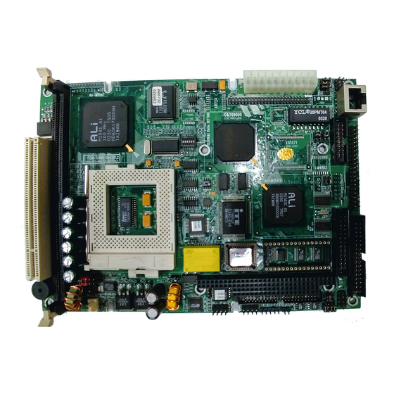
Page 19: Board Layout
Board layout Chapter 1 General Information... -
Page 20: Board Dimensions
Board dimensions 5.08 3.56 40.64 97.16 100.97 119.38 174.63 177.17 193.04 198.12 203.20 dimensions in mm PCM-5896 dimensions PCM-5896 User Manual... -
Page 21: Chapter 2: Installaion
Installation This chapter describes how to set up the main board hardware, including instruc- tions on setting jumpers and connecting peripherals, switches, and indicators. Be sure to read all the safety precautions before you begin the installation proce- dure. Chapter 2 Installation 9... -
Page 22: Jumpers And Connectors
Reserve for future use (default : 1-2 close) COM3 RI pin voltage select COM2 RS-232/422/485 select Audio output select CPU Vio select Level 2 cache select S1 (2~6) CPU Vcore select S3 (1~3) CPU clock select S3 (4~6)/J14 CPU frequency ratio 10 PCM-5896 User Manual... - Page 23 Connectors Label Function CPU fan power connector PC/104 connector USB ports connector IDE drive connector Front panel connector IrDA connector ATX power connector LCD display connector CN10 CD-ROM signal input connector CN11 Keyboard and PS/2 mouse connector CN12 VGA display connector CN13 Audio connector CN14...
-
Page 24: Locating Jumpers (Component Side)
Locating jumpers (Component Side) 12 PCM-5896 User Manual... -
Page 25: Locatting Jumpers (Solder Side)
Locating jumpers (Solder Side) Chapter 2 Installation 13... -
Page 26: Locating Connectors
Locating connectors CN 3 CN 9 CN 6 CN 5 CN 8 CN 7 CN 2 CN 10 LED1 CN11 CN15 CN 17 CN 13 CN 12 CN 14 CN 16 14 PCM-5896 User Manual... -
Page 27: Setting Jumpers
Setting jumpers You can configure your card to match the needs of your application by setting jumpers. A jumper is the simplest kind of electric switch. It consists of two metal pins and a small metal clip (often protected by a plastic cover) that slides over the pins to connect them. To “close”... -
Page 28: Cpu Installing And Upgrading
When you install a new CPU, be sure to adjust the board settings, such as CPU frequency ratio. Improper settings may damage the CPU. 16 PCM-5896 User Manual... -
Page 29: Installing Dram (Dimms)
Installing DRAM (DIMMs) System Memory The left edge of the PCM-5896 contains a socket for 168-pin dual inline memory module (DIMM). The socket uses 3.3 V unbuffered synchronous DRAM (SDRAM). DIMM is available in capacities of 16, 32, 64, or 128 MB. The socket can be filled in the DIMM of any size, giving your PCM-5896 single board computer between 16 and 128 MB of memory. -
Page 30: Clear Cmos (J2)
You can use J2 to clear the CMOS data if necessary. To reset the CMOS data, place a jumper on J2 for just a few seconds, and then remove the jumper. Clear CMOS (J2) Protect* Clear CMOS *default 18 PCM-5896 User Manual... -
Page 31: Doc Address Select (J3)
DOC address select (J3) The DiskOnChip 2000 occupies an 8 Kbyte window in the upper memory address range of D400 to E000. You should ensure this does not conflict with any other device's memory address. J3 controls the memory address of the Flash disk. DiskOnChip 2000 memory address (J3) Memory address (HEX) DISABLE... -
Page 32: Atx Soft-Power Switch Connector (J4)
It is a 2-pin female connector. Plug this connector to the Soft-Power switch connector marked J8. COM2 RS-232/422/485 select (J6, J11) The PCM-5896 COM2 serial port can be selected as RS-232, RS-422, or RS-485 by setting J6 & J11. COM2 Select (J6, J11) RS-232*... -
Page 33: Lcd Clock Signal Select (J7)
LCD clock signal select (J7) You can select the LCD control signal by setting J7. The following charts show the available option. LCD clock signal select (J7) ASHF CLK SHF CLK * *default LCD driving voltage select (J8) You can select the LCD connector CN9 (pin 5 and pin 6) driving voltage by setting J8. -
Page 34: Com3/Com4 Ri Pim Voltage Select (J10, J5)
Audio output select (J12) You can select the output mode of onboard audio connector (CN13) by setting J12. "Speaker out" is the output signal amplified by onboard amplifier Audio output select (J12) Line out Speaker out * *default 22 PCM-5896 User Manual... -
Page 35: Cpu Vio Select (J13)
CPU Vio select (J13) J13 must be set to match the CPU type. The CPU I/O voltage (Vio) can be set to 3.3V or 2.5V. CAUTION : Improper settings may damage the CPU ! CPU Vio select (J13) * 3.3V 2.5V (Intel Tillamook only) 1 3 5 7... -
Page 36: S1 (2~6) Cpu Vcore Select
S1 (2~6) CPU Vcore select S1 must be set to match the CPU type. The table below shows the available configurations. CAUTION: Improper settings may damage the CPU! * default 1 : ON 0 : OFF 24 PCM-5896 User Manual... -
Page 37: S3 (1~3) Cpu Clock Select
S3 (1~3) CPU clock select CPU core frequency = External CPU clock (60~100 MHz) * CPU frequency ratio (2~5.5X). The following table shows the available CPU external clock configurations. CAUTION: Improper settings may damage the CPU! * default 1 : ON 0 : OFF Chapter 2 Installation 25... -
Page 38: S3 (4~6) / J14 Cpu Freguency Ratio
S3 (4~6) / J14 set the frequency ratio between the internal frequen- cy of the CPU and the Exteral frequency (called the FSB, Front Side Bus) within the CPU. CAUTION: Improper settings may damage the CPU! * default 1 : ON 0 : OFF a l l 26 PCM-5896 User Manual... -
Page 39: Power Connectors (Cn8, Cn1)
Power connectors (CN8, CN1) ATX power connector (CN8) The ATX power supply uses 20-pin connector shown below. Make sure you plug in the right direction. (CN8) ATX power connector Signal Signal -12V +5 V 5V SB +12V CPU fan power connector (CN1) Plug in the fan cable to the 3-pin fan connector onboard. -
Page 40: Usb Connector (Cn3)
USB connector (CN3) The PCM-5896 provides two USB (Universal Serial Bus) interfaces, which give complete plug and play, hot attach/detach for up to 127 external devices. The USB interfaces comply with USB specification Rev. 1.0, and can be disabled in the system BIOS setup. -
Page 41: Ide Hard Drive Connector (Cn5)
IDE hard drive connector (CN5) You can attach one or two Enhanced Integrated Device Electronics hard disk drives to the mainboard's internal controller. The mainboard's IDE controller uses a PCI local-bus interface. This advanced interface supports faster data transfer and allows the IDE hard drive to exceed 528 MB. -
Page 42: Ide Hard Drive Connector (Cn5)
DATA 14 DATA 0 DATA 15 SIGNAL GND IO WRITE IO READ IO CHANNEL READY 28 IRQ14 IOCS16 ADDR 1 ADDR 0 ADDR 2 HARD DISK SELECT 0 HARD DISK SELECT 1 IDE ACTIVE MGND MVCC 30 PCM-5896 User Manual... -
Page 43: Front Panel Connector (Cn6)
Reset switch- (GND) Speaker The mainboard can drive an 8Ω external speaker at 0.5 watts. If there is no external speaker, the PCM-5896 provides an on-board buzzer as an alternative. LED interface The front panel LED indicator for hard disk access is an active low signal (24 mA sink rate). -
Page 44: Irda Connector (Cn7)
IR (4Mbps, 2 meters). Install infrared module onto IrDA connector and enable infrared function from BIOS setup. Make sure to have correct orientation when you plug onto IrDA connector. IrDa connector (CN7) Signal FIrRx IrRx IrTx 32 PCM-5896 User Manual... -
Page 45: Display Connectors (Cn9, Cn12)
Display connectors (CN9, CN12) The mainboard's PCI SVGA interface can drive conventional CRT displays and is capable of driving a wide range of flat panel displays, including electroluminescent (EL), gas plasma, passive LCD, and active LCD displays. The board has two connectors to support these displays, one for standard CRT VGA monitors and one for flat panel displays. -
Page 46: Lcd Connector (Cn9)
Configuration of the VGA interface is done completely via the software utility. You do not have to set any jumpers. LCD connector (CN9) Signal Signal +12 V +12 V +5 V +5 V ENAVEE SHF CLK FLM (V SYS) LP (H SYS) ENABKL 34 PCM-5896 User Manual... -
Page 47: Cd Audio Connector (Cn10)
CD Audio connector (CN10) This connector is used to connect to a CD audio cable. CD Audio connector (CN10) Signal CD_L CD_R Keyboard and mouse connector (CN11) The mainboard provides a keyboard connector which supports both a keyboard and a PS/2 style mouse. In most cases, especially in embedded applications, a keyboard is not used. -
Page 48: Audio Connector (Cn13)
Audio connector (CN13) The PCM-5896 provides all major audio signals on a 14-pin flat- cable connector, CN13. Attach the Mic In, Line In, and Audio Out to the corresponding pins as shown in the following table. Audio connector (CN13) Signal... -
Page 49: Parallel Port Connector (Cn14)
Parallel port connector (CN14) Normally, the parallel port is used to connect the board to a printer. The mainboard includes an onboard parallel port, accessed through CN14, a 26-pin flat-cable connector. You need an adapter cable if you use a traditional DB-25 connector. The cable has a 26-pin connector on one end and a DB-25 connector on the other. -
Page 50: 100Base-Tx Ehternet Connector (Cn15)
100Base-Tx Ethernet connector (CN15) This 100Base-Tx Ethernet connector is a standard RJ-45 connec- tor. The onboard Realtek RTL8139A fast Ethernet controller supports 10Mb/s and 100 Mb/s N-way auto-negotiation operation. 100Base-Tx Ethernet connector (CN15) Signal Signal 38 PCM-5896 User Manual... -
Page 51: Serial Ports (Cn16)
Serial ports (CN16) The PCM-5896 offers four serial ports, three RS-232 and one RS- 232/422/485. These ports allow you to connect them to serial devices (mouse, printers, etc.). COM 1-4 RS-232/422/485 serial ports (CN16) COM1, COM2, COM3, COM4 RS-232/422/485 serial port... -
Page 52: Floppy Drive Connector (Cn17)
When the slot is up, pin number 1 should be on the right. Check the documentation that came with the drive for more information. If you desire, connect the B: drive to the connectors in the middle of the cable as described above. 40 PCM-5896 User Manual... -
Page 53: Floppy Drive Connector (Cn17)
Floppy drive connector (CN17) Floppy drive connector (CN17) Signal Signal DENSITY SELECT DRIVE TYPE INDEX MOTOR 0 DRIVE SELECT 1 DRIVE SELECT 2 MOTOR 1 DIRECTION STEP WRITE DATA WRITE GATE TRACK 0 WRITE PROTECT READ DATA HEAD DELECT DISK CHANGE Chapter 2 Installation 41... -
Page 54: Ethernet Led Signal Connectors (Led1)
The PCM-5896 supports three sets of LED connector for external LED indicators. Ethernet active signal LED Flashing Tx or Rx LEDs indicate that the PCM-5896 is transmitting or receiving data. Ethernet link signal LED A continuously lit LED indicates good linkage between the PCM-5896 and its supporting hub. -
Page 55: Diskonchip Socket (U23)
DiskOnChip socket (U23) The DiskOnChip 2000 family of products provides a single chip solid-state flash disk in a standard 32-pin DIP package. The DiskOnChip 2000 is a solid-state disk with no moving parts, resulting in a significant reduction in power consumption and an increase in reliability. -
Page 56: Diskonchip (Doc) 2000 Installation
4. Go to the BIOS Setup Utility by hitting the <DEL> key. Set the type of Primary Master or C: Drive as Not Installed. 5. Remove the floppy disk from the drive A: and leave the BIOS Setup Utility. The system should boot from the DOC. 44 PCM-5896 User Manual... -
Page 57: Chapter 3 Award Bios Setup
This chapter describes how to configure the BIOS for the PCM-5896. Chapter 3 Award BIOS Setup... -
Page 58: Starting Setup
Ctr-Alt-Del. If you do not press the keys at the correct time and the system does not boot, an error message appears and you are again asked to PRESS F1 TO CONTINUE, DEL TO ENTER SETUP PCM-5896 User Manual... -
Page 59: Setup Keys
These keys helps you navigate in Setup: Up arrow Move to previous item Down arrow Move to next item Left arrow Move to the item in the left hand Right arrow Move to the item in the right hand Main Menu: Quit and not save changes into CMOS RAM Other pages: Exit current page and return to Main Menu... -
Page 60: Getting Help
The Chipset defaults have been carefully chosen by Award Software or your system manufacturer for the best performance and reliability. Even a seemingly small change to the Chipset setup may causing the system to become unstable. PCM-5896 User Manual... - Page 61 Standard CMOS Options in the original PC AT-compatible BIOS. BIOS Features Award Software enhanced BIOS options. Chipset Features Options specific to your system chipset. Power Advanced Power Management (APM) Management options. PnP/PCI Plug and Play standard and PCI Local Bus Configuration configuration options.
- Page 62 Load Setup Setup defaults are factory settings for Defaults optimal-performance system operations. Save & Exit Save settings in nonvolatile CMOS Setup RAM and exit Setup. Exit Without Abandon all changes and exit Setup. Save PCM-5896 User Manual...
-
Page 63: Standard Cmos Setup
When you choose the STANDARD CMOS SETUP option from the INITIAL SETUP SCREEN menu, the screen below is displayed. Chapter 3 Award BIOS Setup... - Page 64 IDE hard drives. When you select type AUTO for a hard drive, the BIOS detects its specifications during POST, every time the system boots. If you do not want to select drive type AUTO, other methods of PCM-5896 User Manual...
- Page 65 selecting the drive type are available: 1.Match the specifications of your installed IDE hard drive(s) with the preprogrammed values for drive types 1 through 45. 2.Select USER and enter values into each drive parameter field. 3.Use the IDE HDD AUTO DECTECTION function in Setup. Here is a brief explanation of drive specifications: •Type: The BIOS contains a table of pre-defined drive types.
- Page 66 Liquid crystal display Auxiliary monitor AUTO The BIOS autosenses the device in use (This value lets you switch between devices without being left "in the dark"). LCD & CRT Display on both devices PCM-5896 User Manual...
- Page 67 Pannel: This selection item allows user to select LCD BIOS to match the LCD types. There are eight, LCD types available for users to select as their LCD display modes as below: s t i Chapter 3 Award BIOS Setup...
- Page 68 CPU. Modern personal computers may contain up to 64 MB, 128 MB, or more. • Base Memory Typically 640 KB. Also called conventional memory. The DOS operating system and conventional applications use this area. PCM-5896 User Manual...
- Page 69 • Extended Memory Above the 1-MB boundary. Early IBM personal computers could not use memory above 1 MB, but current PCs and their software can use extended memory. • Other Memory Between 640 KB and 1 MB; often called High memory. DOS may load terminate-and-stay-resident (TSR) programs, such as device drivers, in this area, to free as much conventional memory as possible for applications.
-
Page 70: Bios Features Setup
By choosing the BIOS FEATURES SETUP option from the INITIAL SETUP SCREEN menu, the screen below is displayed. PCM-5896 User Manual... - Page 71 The displayed configuration is based on the manufacturer's SETUP DEFAULTS settings. Virus Warning When enabled, you receive a warning message if a program (specifically, a virus) attempts to write to the boot sector or the partition table of the hard disk drive. You should then run an anti- virus program.
- Page 72 Software that resides in a read-only memory (ROM) chip on a device is called firmware. The AwardBIOS permits shadowing of firmware such as the system BIOS, video BIOS, and similar operat- ing instructions that come with some expansion peripherals, such as, for example, a SCSI adaptor. PCM-5896 User Manual...
- Page 73 Shadowing copies firmware from ROM into system RAM, where the CPU can read it through the 16-bit or 32-bit DRAM bus. Firmware not shadowed must be read by the system through the 8- bit X-bus. Shadowing improves the performance of the system BIOS and similar ROM firmware for expansion peripherals, but it also reduces the amount of high memory (640 KB to 1 MB) avail- able for loading device drivers, etc.
-
Page 74: Chipset Features Setup
By choosing the CHIPSET FEATURES SETUP option from the INITIAL SETUP SCREEN menu, the screen below is displayed. PCM-5896 User Manual... - Page 75 The displayed configuration is based on the manufacturer's SETUP DEFAULTS settings. This section allows you to configure the system based on the specific features of the installed chipset. This chipset manages bus speeds and access to system memory resources, such as SDRAM. It also coordinates communications between the conventional ISA bus and the PCI bus.
- Page 76 EMI. This benefit may in some cases be outweighed by problems with timing-critical devices, such as a clock-sensitive SCSI device IN0-IN6(V) These fields display the current voltage of up to seven voltage input lines, if your computer contains a monitoring system. PCM-5896 User Manual...
-
Page 77: Powr Management Setup
By choosing the POWER MANAGEMENT option from the INITIAL SETUP SCREEN menu, the screen below is displayed. Chapter 3 Award BIOS Setup... - Page 78 SL CPUs. Inactivity period is 1 minute in each mode. User Define Set each mode individually. Select time-out periods in the section for each mode, below. Min Saving Minimum power savings. Inactivity period is 1 hour in each mode (except the hard drive). PCM-5896 User Manual...
- Page 79 PM Control by APM If Advanced Power Management (APM) is installed on your system, selecting Yes gives better power savings. MODEM Use IRQ Name the interrupt request (IRQ) line assigned to the modem (if any) on your system. Activity of the selected IRQ always awakens the system.
- Page 80 All other devices still operate at full speed. Suspend Mode After the selected period of system inactivity, the chipset enters a hardware suspend mode, stopping the CPU clock and possibly causing other system devices to enter power management modes. PCM-5896 User Manual...
-
Page 81: Pnp/Pci Configuration Setup
By choosing the PNP/PCI CONFIGURATION SETUP option from the initial SETUP SCREEN menu, the screen below is displayed. Chapter 3 Award BIOS Setup... - Page 82 Legacy ISA Devices compliant with the original PC AT bus specification, requiring a specific interrupt (such as IRQ4 for serial port 1). PCI/ISA PnP Devices compliant with the Plug and Play standard, whether designed for PCI or ISA bus architecture. PCM-5896 User Manual...
- Page 83 DMA n Assigned to When resources are controlled manually, assign each system DMA channel as one of the following types, depending on the type of device using the interrupt: Legacy ISA Devices compliant with the original PC AT bus specification, requiring a specific DMA channel PCI/ISA PnP Devices compliant with the Plug and Play standard, whether designed for PCI or ISA bus architecture.
- Page 84 LOAD BIOS DEFAULTS loads the default system values directly from ROM. The BIOS DEFAULTS provides the most stable settings, though they do not provide optimal performance. PCM-5896 User Manual...
-
Page 85: Load Setup Defaults
LOAD SETUP DEFAULTS, on the other hand, provides for maximum system performance. If the stored record created by the setup utility becomes corrupted (and therefore unusable), BIOS defaults will load automatically when you turn the power on. Chapter 3 Award BIOS Setup... - Page 86 By choosing the INTEGRATD PERIPHERALS option from the initial SETUP SCREEN menu, the screen below is displayed. PCM-5896 User Manual...
- Page 87 The displayed configuration is based on the manufacturer's SETUP DEFAULSTS settings. On-Chip Primary IDE The onboard chipset contains a PCI IDE interface with support for two IDE channels. Select Enabled to activate the primary and/or secondary IDE interface. Select Disabled to deactivate this inter- face, if you install a primary and/or secondary add-in IDE interface.
- Page 88 ECP Mode Use DMA Select a DMA channel for the port. EPP Mode select Select EPP port type 1.7 or 1.9. Onboard Serial Port 3. Serial Port 3 Use IRQ. Onboard Serial Port 4. Serial Port 4 Use IRQ. PCM-5896 User Manual...
- Page 89 You can set either SUPERVISOR or USER PASSWORD, or both of them. The difference between the two is that the supervisor password allows unrestricted access to enter and change the options of the setup menus, while the user password only allows entry to the program, but not modify options.
- Page 90 System Enter a password each time the system boots and when ever you enter Setup. Setup Enter a password when ever you enter Setup. NOTE: To clear the password, simply press Enter when asked to enter a password. Then the password function is disabled. PCM-5896 User Manual...
-
Page 91: Ide Hdd Auto Detection
The IDE HDD AUTO DETECTION utility can automatically detect the IDE hard disk installed in your system. You can use it to self- detect and/or correct the hard disk type configuration. You need to repeat the setup for each of the IDE combinations: Chapter 3 Award BIOS Setup... - Page 92 CMOS memory. The microprocessor will check this every time you turn your system on and compare this to what it finds as it checks the system. This record is required for the system to operate. PCM-5896 User Manual...
- Page 93 Seleting this option and press <Enter> lets you exit the setup program without recording any new values or changing old ones. Chapter 3 Award BIOS Setup...
- Page 94 PCM-5896 User Manual...
- Page 95 This chapter provides information about: • Driver types and installation...
- Page 96 This chapter describes the operation and installation of the display drivers supplied on the Supporting CD-ROM that are shipped with your product. The onboard VGA adapter is based on the CHIPS VGA Flat Panel/CRT controller and is fully IBM VGA compatible. This controller offers a large set of extended functions and higher resolutions.
- Page 97 The instructions in this manual assume that you understand elementa- ry concepts of MS-DOS and the IBM Personal Computer. Before you attempt to install any driver from the Supporting CD-ROM, you should: • Know how to copy files from a CD-ROM to a directory on the hard disk •...
- Page 98 Ò Ò These drivers are designed to work with Microsoft Windows . You Ò just install these drivers through the Windows operating system. Ò 1. Install Windows 95 as you normally would for a VGA display. Click the Start button, go to Settings and click on Control Panel.
- Page 99 Click the setting buttom, then click the Advanced Properties icon into the Advanced Display properties windows, show as figure2: figure 2...
- Page 100 click on Change Display Type. In the Change Display Type window, click on the Change button under Adapter Type into the select Device window show as figure 3: This will bring up the Select Device window. figure 3...
- Page 101 2. Place the Supporting CD-ROM in your CD-ROM drive. figure 4 In the Select Device window, click on Have Disk, Select Browse, and find the Win95 driver "chips95.inf" in the Supporting CD- ROM: cd-rom: \CD ROM\model name\driver\vga driver \win95\chips95.inf and then click OK. "cd-rom"...
-
Page 102: Driver Installation
The name of the Chips And Tech "69000 PCI " driver will appear highlighted in the Models list boxfhow as figure. Click OK to start the driver installation show as figure 5: figure 5... - Page 103 3. Once the installation is complete, the Advanced display Properties window will reappear. Show as figure 6: figure 6...
- Page 104 Click on close to close the window. Then the Display Properties window will reappear. Show as figure 7: figure 7...
- Page 105 Click on Apply. Restart the system for the new settings to take effect, show as figure 8: figure 8...
- Page 106 These drivers are designed to work with Microsoft Windows Version 3.1. You should install these drivers through Windows. 1. Install Windows as you normally would for a VGA display. Run Windows to make sure that it is working correctly. 2. Place the Supporting CD-ROM into your CD-ROM drive. In Windows Program Manager, choose File from the Options Menu.
- Page 107 These drivers are designed to function with the OS/2 Version 4.0, 3.0 and 2.11 operating systems. To install this driver, do the following steps: 1. Open an OS/2 full screen or windowed session. 2. Place the Supporting CD-ROM into your CD-ROM drive. 3.
- Page 108 6. When the installation is complete, you will need to shut down and then restart the system for the changes to take effect. Make sure to remove the installation diskette before restarting the system.
- Page 109 Ò Ò These drivers are designed to work with Microsoft Windows Ò 1. Install Windows NT 3.51 as you normally would for a VGA display. Click the Star buttom, go to Settings and click on Control Panel icon. Then choose the Display and double click on the icon. In the Display Properties window, click the Setting buttom, then click the Display Type buttom into the Display Type windows, then click on Change buttom from the Adapter Type icon.
-
Page 110: Driver Installation
Ò 1. Install Windows NT 4.0 as you normally would for a VGA display. Click the Star buttom, go to Settings and click on Control Panel icon. Then choose the Display and double click on the icon. In the Display Properties window, click the Setting buttom, then click the Display Type buttom into the Display Type windows, then click on Change buttom from the Adapter Type icon. - Page 111 This chapter describes how to configure the Etherent Card to match your applica- tion requirements. Chapter 5 Software Configuration...
- Page 112 The Ethernet Setup Menu also offers three very useful diagnos- tic functions. These are: 1. Run EEPROM test 2. Run Diagnostics on Board 3. Run Diagnostics on Network Each option has its own display screen which shows the format and result of any diagnostic tests undertaken. PCM-5896 User Manual...
- Page 113 This PCM-5896 is equipped with an audio interface that records and playback CD- quality audio. This chapter provides instructions for installing the software drivers on the included CDROM. Chapter 6 Software Configuration 101...
- Page 114 Creative Labs, Inc. The audio interface can record, compress, and play back voice, sound, and music with built-in mixer control. The PCM-5896 on board audio interface also supports the Plug and Play (PnP) standard and provides PnP configuration for the audio, FM, Ò...
- Page 115 After turning on the system, Windows 95 begins loading and starts detecting new hardware installed on the system. Tip: If you want to install the drivers manually, or your Windows 95 does not detect the new audio hardware, please perform the same installation procedure as described in NT 4.0 setion.
- Page 116 · SB Audio PCI 64V Legacy Device · Sound Blaster AudioPCI 64V 5. Upon initial installation, the setup process begins setting up the software. 6. Windows 95 makes final changes to the system settings, and you will be prompted to re-boot the system. PCM-5896 User Manual...
- Page 117 Follow these steps to install the audio drivers: 1. Excute the installation wizard named "CTRUN.EXE" in the follow- ing directory: cd-rom : \CD ROM\model name\dirver\Audio\Ctrun "cd-rom" : the drive letter of your CD-ROM drive "model name" : the model number of your product 2.
- Page 118 PCM-5896 User Manual...
-
Page 119: Appendix A Programming The Watchdog Timer
The mainboard is equipped with a watchdog timer that resets the CPU or generates an interrupt if processing comes to a standstill for whatever reason. This feature ensures system reliability in industrial stand-alone and unmanned environments. Appendix A Programming the Watchdog Timer... - Page 120 -- access the I/O port 0x443, e.g. outportb(0x443, data); // refresh watchdog timer * note: if you want to refresh the watchdog timer, you have to disable it first. PCM-5896 User Manual...
- Page 121 outportb(0x444, 0): // set time-out event to reset-system outportb(0x443x 10); // set time-out interval to 10 seconds customer_job(); // execute your job here, be sure your job will finished within 10 seconds outportb(0x443, 0); // refresh watchdog timer, otherwise the system will reset after time-out outputb(0x443, 20);...
- Page 122 PCM-5896 User Manual...
- Page 123 This appendix provides instructions for installing PC/104 modules. Appendix B Installing PC/104 Modules...
- Page 124 • PCM-3910 Breadboard Module • PCM-3810 Solid State Disk Module Installing these modules on the PCM-5896 is a quick and simple operation. The following steps show how to mount the PC/104 modules: Step1 Remove the PCM-5896 from your system, paying particular attention to the safety instructions already mentioned above.
-
Page 125: Appendix B Installing Pc/104 Modules
PC/104 Mounting Support Female Male Main board PC/104 Module PC/104 Module Mounting Diagram 0.300 3.250 3.775 3.575 3.575 0.200 0.200 3.350 0.200 3.550 Appendix B Installing PC/104 Modules... - Page 126 PCM-5896 User Manual...
-
Page 127: Appendix C Optional Extras
Appendix C Optional Extras... - Page 128 , n i " 5 , n i " 5 " 5 l e l c r i c r i t g i l i a l a i , t r , n i & PCM-5896 User Manual...
- Page 129 l a i Appendix C Optional Extras...
- Page 130 PCM-5896 User Manual...
Need help?
Do you have a question about the PCM-5896 and is the answer not in the manual?
Questions and answers