Table of Contents
Advertisement
Advertisement
Table of Contents

Related Manuals for Hytorc Stealth 2


Summary of Contents for Hytorc Stealth 2
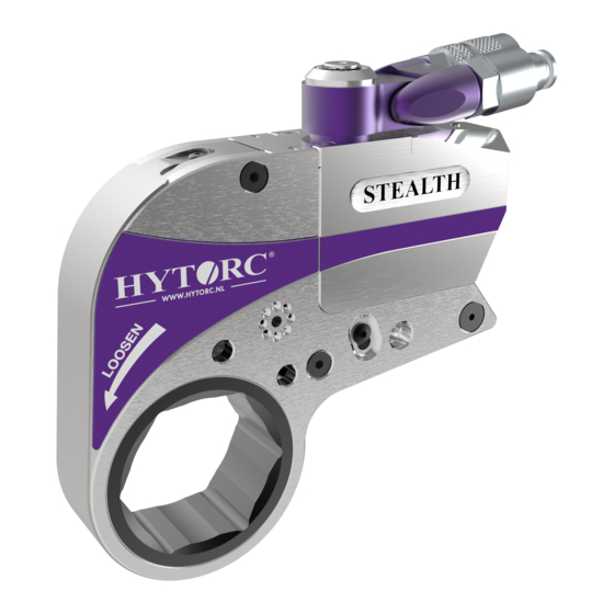
- Page 1 Stealth hydraulic limited-clearance wrench Technical manual...
- Page 2 Details and values given in this manual are average values and have been compiled with care. Details and values are not binding. HYTORC disclaims any liability for damage or detriments suffered as a result of reliance on the information given herein or the use of products, processes or equipment to which this document refers.
-
Page 3: Table Of Contents
Contents About the document ....................5 Purpose of the document ..........................5 How to work with the document ........................5 Languages ..............................5 Illustrations ..............................5 Safety symbols in the document ........................5 Related documents ............................6 Revision history ............................. 6 Contact information ............................. - Page 4 6.7.2 Loosening a bolted flange connectionn ....................30 Automatic shut-off system .......................... 31 Thermal protection ............................. 31 Maintenance ......................33 Preventive maintenance ..........................33 Maintenance by HYTORC .......................... 33 Storing the cables ............................33 Troubleshooting ....................35 Tools ................................35 Pump units ..............................36 8.2.1 General ..............................
-
Page 5: About The Document
About the document About the document Purpose of the document The document shows the information to do these steps: • Install the equipment • Operate the equipment • Maintain the equipment The document contains the original instructions for the jGun pneumatic socket wrench, to which is referred with the term ‘tool’. -
Page 6: Related Documents
Stealth hydraulic limited-clearance wrench User manual Personnel who operates the equipment Revision history Date Revision number Comment 04-08-2016 First version Contact information HYTORC Nederland BV HYTORC Benelux BVBA Platinawerf 8 Ysselaarlaan 65B 6641 TL Beuningen 2630 Aartselaar Nederland België Telefoon: +31 (0)24 3660660 Telefoon: +32 (0)38 705220 Website: www.hytorc.nl... -
Page 7: Veiligheid
Uitrusting • Gebruik uitsluitend door HYTORC goedgekeurde uitrusting. • Gebruikt uitsluitend uitrusting die geschikt is voor en kan worden gecombineerd met de uitrusting van HYTORC. • Pas de uitrusting op geen enkele wijze aan. • Gebruik gereedschappen uitsluitend voor de doeleinden waarvoor ze zijn ontworpen. Gebruik geen kleinere gereedschappen of accessoires voor taken die met een groter gereedschap moeten worden uitgevoerd. -
Page 8: Aanvullende Veiligheidsinstructies
Bij contact tussen metalen delen kunnen vonken ontstaan. Neem de juiste extra maatregelen. • Draag gehoorbescherming. De geluidsemissie van HYTORC pompunits is minder dan 80 dB. • Zorg dat de maximumbedrijfsdruk van de pompunit de maximum toegestane druk van 700 bar (10.000 psi) niet overschrijdt. -
Page 9: Reactiearmen
• Controleer of de moerdop stevig aan het gereedschap vastzit. • Gebruik geen algemene verlengstukken of verkleinende of vergrotende adapters. HYTORC kan accessoires op maat ontwikkelen om veilige en eenvoudige bediening te verzekeren. Neem voor meer informatie contact op met... -
Page 10: Veiligheidssymbolen Op Het Gereedschap
Onbedoelde toepassingen zijn onder andere: • Gebruik van niet door HYTORC goedgekeurde uitrusting • Gebruikt van uitrusting die niet geschikt is voor en niet kan worden gecombineerd met de uitrusting van HYTORC • Het op enige manier wijzigen of aanpassen van uitrusting... -
Page 11: Description
Intended use The Ice hydraulic socket wrench is a tool used for both your torque and tension applications. Different reaction arms and sockets can be used with the tool. HYTORC hydraulic tools have an accuracy of ± 3%. Overview Electric pump unit 2. -
Page 12: Electric Pump Unit
Description Electric pump unit The pressure range of the pump unit is 50 bar - 700 bar. Hose connection (male coupling) (supply hose) (A) Pressure control valve / Wingnut Hose connection (female coupling) (re- turn hose) (B) Pressure relief valve Oil filling point Remote control Oil drain point... -
Page 13: Pneumatic Pump Unit
Description Pneumatic pump unit The pressure range of the pump unit is 50 bar - 700 bar. Hose connection (male coupling) (supply hose) (A) 2. Hose connection (female coupling) (re- turn hose) (B) 3. Oil filling point 4. Oil drain point 5. -
Page 14: Hydraulic Socket Wrench
Description Hydraulic socket wrench Hose connection (male coupling) (supply hose) (A) 2. Hose connection (female coupling) (re- turn hose) (R) 3. Square drive for socket connection 4. Disengagement lever for reaction pawl 5. Drive retainer 6. Spline for connection of reaction arm Mounting point for safety handle... -
Page 15: Accessories
Description Accessories 3.6.1 Safety handle Procedure For more convenience and safety, install the safety handle to the tool or the reaction arm. 3.6.2 BoltSafe load tester The BoltSafe load tester has a reading system and one or more sensors. The sensors monitor the bolt load in bolted joints. The sensors are sha- ped and used as a regular washer. -
Page 16: Insert
Description 3.6.4 Insert The tool can be extended with a torque and angle sensor for digital registration of bolting. Procedure Place the sensor on the tool and 2. Place the tool on the bolt head. 3. Apply pre-torque (A). 4. Apply torque until the angle (B) is reached. 3.6.5 Stacking nuthead Procedure... -
Page 17: Installation
Installation Installation Hydraulic hoses The working pressure of the hydraulic hoses is up to 700 bar. The safety factor of the hydraulic hoses is factor 4. 4.1.1 Hydraulic hose connections Use a twin hose to connect the pump unit to the tool. A twin hose consists of two hoses. The supply hose has two ends with female couplings. - Page 18 Loosen the locking ring of the female coupling from the male coupling and pull the couplings apart. Toothed screw-type safety couplings (HYTORC 716) The coupling is identical to the screw-type safety couplings (type Pioneer), but both coupling are toothed. The male coupling has a toothed locking ring which is axially displacea- ble.
-
Page 19: Connecting The Hydraulic Hoses
Installation 4.1.2 Connecting the hydraulic hoses Warning: • Make sure that the system is depressurized. • Make sure that the hydraulic hoses are securely connected to both the pump unit and the tool. Make sure that there is no clearance between the male couplings and the female couplings. If the hydraulic hoses become loose, no hydraulic oil will flow through the hoses and the tool will not operate. -
Page 20: Power Supply (Electric Pump Units)
Installation Power supply (electric pump units) There are different types of electric pump units to operate the tool: 230V pump unit 2. 400V pump unit Warning: • Do not use an extension cable longer than necessary. • Make sure that the length of the extension cable does not exceed 50 metres. •... -
Page 21: Air Supply (Pneumatic Pump Units)
Explosion protection (pneumatic pump units) HYTORC can make the system (pump, hose and tool) explosion proof. The tools will be equipped with anodized swi- vels. Metal springs will be fitted onto the couplings of the swivel, the twin hose and the pump unit. The rubber feet of the pump unit will be replaced by metal studs. - Page 22 Installation...
-
Page 23: Reaction Arms
Reaction arms Reaction arms The reaction arms can be used together with hydraulic tools, pneumatic tools and electric tools. There are different types of reaction arms to operate the tool. Reaction pad Procedure: Place the reaction arm as shown. 2. Place the tool over the nut as far as possible. Alco reaction arm Procedure: Place the reaction arm as shown. -
Page 24: Holding Plate
Reaction arms Holding plate The holding plate allows to use double-drive. Multiple variants are available for use with the HYTORC WasherTM or HYTORC LoadDISCTMC Procedure: Place the HYTORC WasherTM or HYTORC LoadDISCTM under the regular nut. 2. Place the tool with the holding plate over the nut and reaction... -
Page 25: Operation
200 bar (2,900 psi), 400 bar (5,800 psi) and 700 bar (10,000 psi) respectively. • all moving parts of the tool are clean and sufficiently lubricated with a high-quality NLGI #2 molybdenum disulfide grease. For subsea applications, HYTORC recommends Womi lube. • the square drive and the drive retainer are securely fitted. -
Page 26: Pneumatic Pump Unitt
Operation 3.2.1 Pneumatic pump unitt Procedure Set the on/off switch (A) to the on position to switch on the pump unit. 2. Press and hold the start button (B) to increase the pressure in the pump unit and operate the tool. 3. -
Page 27: Torque
Each HYTORC torque wrench has its own pressure/torque chart. The pressure/torque chart is separately supplied with your HYTORC torque wrench. Refer to the pressure/ torque chart to find the required torque (Nm / ft.lb.) and read the required pressure (bar / psi). -
Page 28: Setting The Torque
Operation 4.1.2 Setting the torque Warning: • Always set the pressure from low pressure to high pressure. Loosen the wingnut (A) on the pressure control valve (B) of the pump unit. 2. Turn the pressure control valve (B) counter- clockwise to set the pressure as low as possible. 3. -
Page 29: Determining The Direction Of Rotation
Operation Determining the direction of rotation Procedure To tighten a bolted connection, place the tool onto the bolt as shown. Refer to the marking “TIGHTEN” on the tool. 2. To loosen a bolted connection, place the tool onto the bolt as shown. -
Page 30: Tightening A Bolted Flange Connection
• Always set the pressure as low as possible to loosen the nut or the bolt. • If you must constantly use a high pressure to loosen the nut or the bolt, use a heavier HYTORC tool. Contact your local HYTORC representative for more information. -
Page 31: Automatic Shut-Off System
Operation Automatic shut-off system The electric pump unit is equipped with an automatic shut-off system. The pump unit will be switched off after approxi- mately 30 seconds of non-operation to prevent wear and overheating. To restart the pump unit, press the start button on the remote control. - Page 32 Operation...
-
Page 33: Maintenance
• Clean dirty hose couplings. Replace defective hose couplings. • Replace the hydraulic oil when it has a white, milky look. Maintenance by HYTORC • Have the tool fully disassembled, cleaned, inspected and lubricated at least once a year. • When the tool is dirty because of sand or another abrasive, have the tool fully disassembled, cleaned, inspected and lubricated immediately. - Page 34 Maintenance...
-
Page 35: Troubleshooting
See Hydraulic hose connections on page 19. The male coupling and the female Use a HYTORC twin hose. coupling have been interchanged. The tool moves slower than usual. There is a leakage in the system. Adjust the pump pressure to 700 bar (10,000 psi) and switch off the pump unit while holding the start button. -
Page 36: Pump Units
Problem Possible cause Solution The pump pressure is not repeatedly The pressure control valve is dirty or Contact your local HYTORC repre- accurate with a fixed setting. defective. sentative. The pump unit operates and provides The hose couplings on the tool Securely tighten the female coupling pressure, but the tool does not move. -
Page 37: Electric Pump Units
See Power supply (electric pump units) on page 22. The motor operates, but the tool does The remote control cable is dama- Contact your local HYTORC repre- not make a complete stroke. ged. sentative. The valve block is defective. - Page 38 Troubleshooting...
-
Page 39: Technical Data
Technical data Technical data Stealth 2 Length (L) 140,5 mm 5,53” Height (H) 106,9 mm 4,21” Width (W) 31,8 mm 1,25” Radius (R), min. 26,1 mm 1,03” Radius (R), max. 44,6 mm 1,76” Minimum torque 377 Nm 278 ft.lb Maximum torque 2.534 Nm... -
Page 40: Stealth 8
Technical data Width (W) 53,3 mm 2,10” Radius (R), min. 44,88 mm 1,77” Radius (R), max. 73,4 mm 2,89” Minimum torque 1.625 Nm 1.199 ft.lb. Maximum torque 10823 Nm 7.984 ft.lb. Weight 9,2 kg 20,3 lb. Stealth 14 Length (L) 237,4 mm 9,35”... -
Page 41: Swivel Rotation
Note: The tool is not suitable for use in explosive environments. Your HYTORC dealer is able to modify your HYTORC equipment (except for electric tools) to comply with the directives EPS 13 ATEX 2 561 X and EX II 2 G EX c IIB T4. -
Page 42: Maximum Torque Values (Stacking Nutheads And Male Hex Drives)
Technical data Maximum torque values (stacking nutheads and male hex drives) Maximum torque (Nm) Size (mm) Normal Break 1.020 1.612 1.768 2.500 2.775 2.950 3.600 4.000 4.800 7.480 8.296 9.928 10.880 16.320 17.952 20.400 22.440 30.600 33.592 43.520 47.736 Maximum torque (Nm) Size (mm) Normal Break... - Page 43 Note: If the area of the hex drive is smaller than the ratch- et link drive, HYTORC will dis- claim any liability for broken stacking nutheads and hex drives. These male hex sock- ets are excluded from warran- ty claims: •...
- Page 44 Technical data...
-
Page 45: 10. Declaration Of Conformity
Declaration of Conformity 10. Declaration of Conformity Declaration of Conformity (according to Annex II.1.A of the Machinery Directive) Fabrikant: HYTORC BV Platinawerf 8, 6641 TL Beuningen Nederland Telefoon: +31 (0) 24 3660 660 Declare under our own responsibility: We are the manufacturer of the Stealth hydraulic limited-clearance wrench with optional accessories. - Page 46 Declaration of Conformity...
Need help?
Do you have a question about the Stealth 2 and is the answer not in the manual?
Questions and answers