
Related Manuals for Inovance MD880 Series


Summary of Contents for Inovance MD880 Series
- Page 1 MD880 Series High Performance Single Drive AC Drive Hardware Guide User Guide Data code 19011400...
-
Page 2: Preface
◆ The instructions are subject to change, without notice, due to product upgrade, specification modification as well as efforts to increase the accuracy and convenience of the user guide. ■ Standards compliance The MD880 series AC drive complies with the directives and standards listed in the following table. Directive Name of Directive... -
Page 3: Revision History
Revision History Revision History Date Version Description October 2020 First release. March 2021 Minor corrections. - 2 -... -
Page 4: Table Of Contents
Contents Contents Preface ............................1 Revision History ......................... 2 Safety Instructions ........................7 Safety Disclaimer ......................... 7 Safety Levels and Definitions ..................... 7 Safety Instructions ....................... 7 Safety Signs ........................11 1 Product Information ......................13 1.1 Overview ........................13 1.2 Nameplate and Model Number .................. - Page 5 Contents ................32 2.5.1 Heat Dissipation Requirements ..........35 2.5.2 Precautions for Installing AC Drives in Cabinets ..........37 2.5.3 Procedure for Installing the AC Drive in a Cabinet ..............43 2.5.4 Dimensions of the Mounting Bracket 2.6 Cover Removal and Mounting ..................44 3 Electrical Installation ......................
- Page 6 Contents 4.8 HPCU Parallel Control Module ..................89 ....................89 4.8.1 Standard Terminals ...................... 90 4.8.2 LED Indicators ................91 4.8.3 Electrical Connection of HPCU 4.9 Applications of HCU ..................... 91 ....................91 4.9.1 SLOT Expansion ............92 4.9.2 Temperature Measurement with AI and AO ................
- Page 7 Contents .................... 127 6.6.1 Standard EMC filter ..................134 6.6.2 Simple EMC Input Filter ..............135 6.6.3 Safety Capacitor and Magnetic Ring 6.7 Selection of the AC Output Reactor ................138 Appendix: Installation of the Sheet Metal Base and Side Entry Output Copper Busbar .. 147 - 6 -...
-
Page 8: Safety Instructions
4) Use this equipment according to the designated environment requirements. Damage caused by improper usage is not covered by warranty. 5) Inovance shall take no responsibility for any personal injuries or property damage caused by improper usage. Safety Levels and Definitions... - Page 9 Safety Instructions WARNING ◆ Do not install the equipment if you find damage, rust, or indications of use on the equipment or accessories. ◆ Do not install the equipment if you find water seepage, component missing, or damage upon unpacking. ◆...
- Page 10 Safety Instructions DANGER ◆ Equipment installation, wiring, maintenance, inspection, or parts replacement must be performed only by professionals. ◆ Installation, wiring, maintenance, inspection, or parts replacement must be performed only by experienced personnel who have been trained with necessary electrical information.
- Page 11 Safety Instructions Power-on DANGER ◆ Before power-on, make sure that the equipment is installed properly with reliable wiring and the motor can be restarted. ◆ Before power-on, make sure that the power supply meets equipment requirements to prevent equipment damage or even a fire. ◆...
-
Page 12: Safety Signs
Safety Instructions Repairing DANGER ◆ Equipment installation, wiring, maintenance, inspection, or parts replacement must be performed only by professionals. ◆ Do not repair the equipment at power-on. Failure to comply will result in an electric shock. ◆ Before inspection and repair, cut off all equipment power supplies and wait at least 15 minutes. - Page 13 Safety Instructions Safety Label Description To prevent overheating of the pre-charge resistor, the interval between switch-ons must not be less than 注意 three minutes! 为防止预充电电阻过热,两次 合闸的时间间隔不小于三分钟 - 12 -...
-
Page 14: Product Information
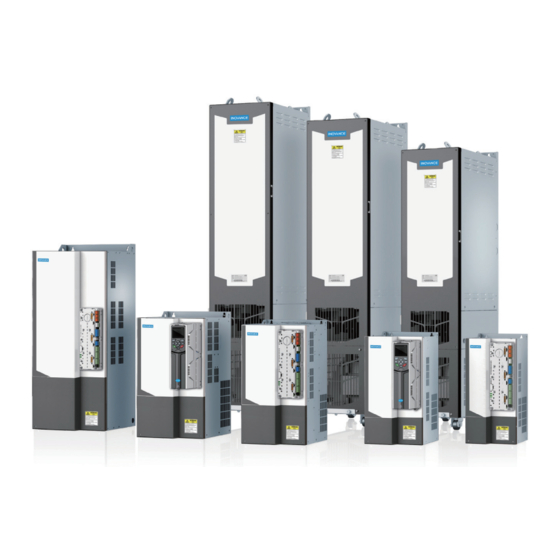
1 Product Information 1.1 Overview The MD880 series AC drive (single drive system) is a general-purpose low-voltage AC drive developed by Inovance. Featuring high power density, compact structure, and high reliability, it can be used for V/F control, sensorless vector control (SVC), and feedback vector control (FVC) of motors. -
Page 15: Voltage And Power Rating
1 Product Information 1.3 Voltage and Power Rating The grid voltage ranges from 3AC 380 V to 480 V. The following table lists the power rating. Table 1-1 Power rating of the MD880 series AC drive (single drive system) Rated Rated Model... -
Page 16: Technical Data And Model Selection
1 Product Information 1.4 Technical Data and Model Selection Table 1-2 Selection of MD880 series AC drive (single drive system) Overall No Overload Light Overload Heavy Overload Weight Loss Dimensions Structure Model (kg) (kW) (W x L x D) Current Power... -
Page 17: Technical Data
MD880-01S- 400 x 1735 x 6.31 0751-4-L MD880-01S- 6.91 0849-4-L 1.5 Technical Data Table 1-3 Technical data of MD880 series AC drive (single drive system) Item Specification Rated input voltage and 400 V system: 380–480 VAC, 50/60 Hz frequency Allowed voltage -15% to +10%;... - Page 18 1 Product Information Item Specification V/F control Motor control Sensorless vector control (SVC) mode Feedback vector control (FVC) 400 V system: 5.5–37 kW: 4 kHz by default; Carrier frequency 45–55 kW: 3.2 kHz by default; 75 kW: 2.5 kHz by default; 90–450 kW: 2 kHz by default V/F control: 1:50 Control...
-
Page 19: Derating
1 Product Information Item Specification Installation Free from direct sunlight, dust, corrosive gas, combustible location gas, oil smoke, vapor, drip, or salt indoor Below 1000 m, derated by 1% per 100 m increase when the Altitude altitude is above 1000 m Maximum altitude: 3000 m Ambient temperature: -10℃... - Page 20 1 Product Information Figure 1-4 Altitude and derating 3) Carrier frequency and derating Table 1-4 Carrier frequency and derating Rated Model Carrier Frequency (kHz) Power MD880- P (kW) 01S-... 0012-4-B 100.00% 100.00% 100.00% 100.00% 100.00% 100.00% 89.56% 80.86% 73.49% 67.24% 0017-4-B 100.00% 100.00% 100.00% 100.00% 100.00% 100.00% 89.33% 80.42% 72.97% 66.50%...
-
Page 21: Overload Capacity
For some drive systems where overload may occur, a proper reference load current is necessary for the MD880 series AC drive (single drive system). When the drive system runs at the reference load current (load duration 300s), an overload occurs. -
Page 22: Overall Dimensions
1 Product Information 1.8 Overall Dimensions 1.8.1 Overall and Mounting Dimensions of Structures T2 to T9 Figure 1-7 Overall and mounting dimensions of structures T2 to T9 Table 1-5 Overall and mounting dimensions of structures T2 to T9 Mounting Hole Overall Dimensions (mm) Mounting Hole Weight Location (mm) -
Page 23: Overall And Mounting Dimensions Of Structures T10 To T12 (Without Reactors)
1 Product Information 1.8.2 Overall and Mounting Dimensions of Structures T10 to T12 (Without Reactors) Figure 1-8 Overall and mounting dimensions of structures T10 to T12 (without reactors) Table 1-6 Overall and mounting dimensions of structures T10 to T12 (without reactors) Mounting Mounting Hole Location Hole Overall Dimensions (mm) -
Page 24: Overall And Mounting Dimensions Of Structures T10 To T12 (With Reactors)
1 Product Information 1.8.3 Overall and Mounting Dimensions of Structures T10 to T12 (With Reactors) Figure 1-9 Overall and mounting dimensions of structures T10 to T12 (with reactor bases) Table 1-7 Overall and mounting dimensions of structures T10 to T12 (with reactor bases) Mounting Mounting Hole Location Hole... -
Page 25: Consumption Of Auxiliary Power
1 Product Information Screw/Bolt Strength Grade Maximum Torque (N·m) Table 1-9 Mechanical connection Screw/Bolt Strength Grade Maximum Torque (N·m) Table 1-10 Insulator connection Screw/Bolt Strength Grade Maximum Torque (N·m) Table 1-11 Cable connector Screw/Bolt Strength Grade Maximum Torque (N·m) 1.10 Consumption of Auxiliary Power Table 1-12 Consumption of auxiliary power HCU Control Module Structure... -
Page 26: Mechanical Installation
For storage of the AC drive, pay attention to the following three aspects: ■ Pack the AC drive with the original packing box provided by Inovance. ■ Do not expose the AC drive to moisture, high temperature, or outdoor direct sunlight for a long time. - Page 27 2 Mechanical Installation Figure 2-1 Transporting equipment before unpacking ■ Ensure that the ground at the installation location is flat and strong enough to bear the weight of the equipment. ■ Structures T9 to T12 are heavy with high centers of gravity, which cannot be placed on a slope with an inclination of more than 5°...
-
Page 28: Acceptance
Check that you have received all the items specified on the delivery note. Notify the shipping company immediately of any missing components or damage. If you have any problem, contact Inovance or the local agent for technical support. DANGER ◆ If the equipment is damaged during transportation, the electrical safety of the cabinet can no longer be ensured. -
Page 29: Installation Clearances And Direction
2 Mechanical Installation Item Quantity This product is installed in a cabinet and must be installed in the final system. The final system must provide a fireproof enclosure, electrical Enclosure enclosure, and mechanical enclosure, and comply with local laws and regulations and relevant IEC standards. - Page 30 2 Mechanical Installation Figure 2-4 Installation clearances of a single AC drive (structures T10 to T12) Power Rating Dimension Requirements (mm) 220–450 kW A2 ≥ 10 B2 ≥ 250 C2 ≥ 50 D ≥ 30 2) Installing multiple AC drives side by side The AC drive dissipates heat from bottom to top.
- Page 31 55–160 kW A ≥ 50 ◆ For Structures T10 to T12, only one AC drive can be installed in a cabinet. If multiple AC drives need to be installed side by side, contact Inovance or the agent. NOTE 3) Installing AC drives above one another...
-
Page 32: Installation Direction
2 Mechanical Installation 2.3.2 Installation Direction The AC drive must be installed vertically upward. Other installation directions are not allowed. Figure 2-7 Installation direction 2.4 Backplate Mounting Backplate mounting is available for structures T2 to T9. See the guidance below for specific model and application scenarios. -
Page 33: Floor Mounting
2 Mechanical Installation Figure 2-8 Backplate mounting of structures T2 to T9 ◆ In this mode, mount the AC drive using all mounting holes; otherwise, the AC drive may fall off or be damaged due to the unbalanced effect on the fixed part during long-time running. - Page 34 2 Mechanical Installation 1) Direct discharging cabinet (without fans on the top) Cabinet top air outlet cover Ventilation airflow Insulation barrier 2200 mm AC drive (T10‒T12) Air inlet of front door 100 mm Figure 2-9 Direct discharging cabinet Table 2-1 Specification of the direct discharging cabinet Effective Area of Quantity Total Air...
- Page 35 2 Mechanical Installation 2) Cabinet with fans on the top Cabinet top air outlet cover Ventilation airflow Insulation barrier 2200 mm AC drive (T10‒T12) Air inlet of front door 100 mm Figure 2-10 Cabinet with fans on the top Table 2-2 Specification of the cabinet with fans on the top Effective Max.
-
Page 36: Precautions For Installing Ac Drives In Cabinets
2 Mechanical Installation As shown in the following figure, the heat vent of the AC drive must be isolated inside the cabinet using a windscreen to ensure that the hot air generated by the AC drive exhausts through the louver on the cabinet top, stopping circulation of the hot air in the cabinet. - Page 37 2 Mechanical Installation ◆ Reserve the installation clearances as specified in Figure 2-4 to ensure sufficient space for heat dissipation of the AC drive. Take the heat dissipation of other equipment in the cabinet into consideration. ◆ A tool such as a sleeve with an extension bar is required for operation on the copper busbar terminals of main circuit power cables.
-
Page 38: Procedure For Installing The Ac Drive In A Cabinet
2 Mechanical Installation 2.5.3 Procedure for Installing the AC Drive in a Cabinet Step Operation Install the fixing beam in the nine fold profile cabinet, as shown in Figure 2-13. Secure the bottom mounting bracket, as shown in Figure 2-14. Assemble the guide rail (option) and connect the guide rail to cabinet. - Page 39 2 Mechanical Installation Figure 2-14 3D view of structures T10 to T12 in the cabinet ◆ If the cabinet has a front door and a back door, the cabinet of 600 mm deep is too small to accommodate structures T10 to T12. In this case, the cabinet of 800 mm deep is recommended.
- Page 40 2 Mechanical Installation Before assembling After assembling Figure 2-16 Assembling the guide rail in the cabinet 4) Installing the AC drive in the cabinet Figure 2-17 Aligning casters of the AC drive to the guide rail - 39 -...
- Page 41 2 Mechanical Installation Figure 2-18 Slowly pushing the AC drive into the cabinet Figure 2-19 Push-in completed - 40 -...
- Page 42 2 Mechanical Installation Figure 2-20 Fixing the AC drive to the beam using the four fixed holes on the back of the AC drive - 41 -...
- Page 43 2 Mechanical Installation ◆ Remove the AC drive from the cabinet according to above steps in reverse order. ◆ Ensure the four fixed holes on the back of the AC drive are connected to the beams securely. ◆ After push-in is complete, remove the baffle on the top of the AC drive. The baffle is used to prevent foreign objects such as screws from falling into the air filter when the AC drive is mounted in the cabinet.
-
Page 44: Dimensions Of The Mounting Bracket
2 Mechanical Installation 2.5.4 Dimensions of the Mounting Bracket 35.5 35.5 580 (780) 32.5 42.5 22.5 6- 6 2-FH6×M 15 2- 10 39.5 See details A 27.5 525( 725) MD 880-01S-0441-4-(L) Note: 30° MD 880-01S-0481-4-(L) 1. This figure is applicable to the PS cabinet: width 800 x depth 600 Mounting Bracket Details A Change... -
Page 45: Cover Removal And Mounting
2 Mechanical Installation 35.5 35.5 580 (780) 42.5 32.5 22.5 2-FH-M6 X 15 See details A 39.5 525 (725) 27.5 MD880-01S-0673-4-(L) Note: MD880-01S-0751-4-(L) 30° 1. This figure is applicable to the PS cabinet: width 800 x depth 600 MD880-01S-0849-4-(L) (width 800 x depth 800). Details A Mounting Bracket Change... - Page 46 2 Mechanical Installation ■ Removing and refitting of the cover of structures T2 to T9 Removal Remove the two fixing screws on the Hold the cover with both hands, push it up, and cover using a screwdriver. Hold the then pull it out downwards to remove the cover. cover while screwing out the screws to prevent it from falling.
- Page 47 2 Mechanical Installation Figure 2-25 Removing the covers of structures T10 to T12 4) Refitting the covers of structures T10 to T12 Refit the covers in a reverse procedure to removal. 5) Hold the upper cover with both hands and align the top of the upper cover with the fixing hooks at the top of the cabinet, as shown in the following figure.
-
Page 48: Electrical Installation
3 Electrical Installation 3 Electrical Installation Figure 3-1 Electrical installation flowchart - 47 -... -
Page 49: Safety Instructions
3 Electrical Installation 3.1 Safety Instructions 3.1.1 Safety Precautions Before Installation Read safety instructions and precautions thoroughly. Electrical installation must be performed by skilled personnel. The following "five safety rules" must always be observed: ■ Disconnect the equipment from power supply. ■... -
Page 50: Insulation Test
3 Electrical Installation 3.1.4 Insulation Test The AC drive has been tested for insulation between the main circuit and the housing at the factory. Therefore, do not perform any withstand voltage and insulation resistance tests on the AC drive again. Check insulation of the motor and motor cables according to the following steps: 1) Check that the motor cables are connected to the motor and they are disconnected from the drive output terminals (U, V, W). -
Page 51: Wiring Of The System
3.2 Wiring of the System Install necessary electrical components on the input/output side of the AC drive to ensure safety and stability of the MD880 series AC drive control system. The following figure shows the system wiring. Braking device (optional) -
Page 52: System Structure
Braking resistor below: terminals (+) and Dissipates regenerative energy during motor deceleration. Use an MDBUN braking unit of Inovance and a Models of 110 kW and recommended braking resistor for models of 110 kW Braking unit above: terminals (+) and and above as needed. -
Page 53: Emc-Compliant Cable Routing
3 Electrical Installation Peripheral Name Mounting Location Function Harmonics are present in the output side of the AC drive. If the motor is routed far away from the servo drive, the following may occur due to large distributed capacitance in the circuit and certain harmonics that Between the AC drive may generate resonance in the circuit: output side and the... -
Page 54: Routing Suggestions
3 Electrical Installation and strong-current circuit cables (power input, AC drive output, and braking resistor connecting cable) of the controlled AC drive must be routed separately with a distance longer than 30 cm to reduce interference on the analog generated by the AC drive and other devices. - Page 55 3 Electrical Installation Interference Sensitive Sensitive Interference Sensitive cable cable cable cable cable Interference cable < 30 cm ≥ 30 cm Figure 3-3 Routing of interfering cables and sensitive cables 2) Route different signal cables separately and isolate different types of signals with the equipotential signal.
- Page 56 3 Electrical Installation 3) For the multicore cable, it is recommended that a cable transmit the same type of signals. If a cable is used to transmit different types of signals, use the cable with conductor shielded, as shown in the following figure: Power signal Digital signal Relay contact signal...
- Page 57 3 Electrical Installation Excessive area PCB with relay PCB with relay contact output contact output Power supply Power supply Figure 3-7 Routing for preventing too large loop area 6) Lay multiple types of cables along the metal block with equipotential connection and separate them to improve internal EMC.
-
Page 58: Connection Of Shielded Power Cables
3 Electrical Installation Figure 3-9 Requirements on shielded power cables 3.4.4 Connection of Shielded Power Cables The input/output shielded power cable and shield inside the power unit must be in large-area contact with the shield plate in the cabinet to achieve good EMC effect. The following figure shows the connection diagram. - Page 59 3 Electrical Installation T12 are connected to the HCU-50 control module through high-speed optical fiber communication cables. PC/SOP-20-880 interface XRO 3 X 11 X 12 Down- OFF Relay output 3 Up-ON GND3 XRO 2 15 VDC 124 Ω RS 485 Relay output 2 HCU-51 AC drive...
- Page 60 3 Electrical Installation PC/SOP-20-880 interface Down XRO 3 X 11 X 12 -OFF Relay output 3 Up -ON GND3 XRO 2 15 VDC RS 485 124 Ω Relay output 2 AC drive HCU-50 XRO 1 Relay output 1 InoLink communication termination resistor selection 跳线...
-
Page 61: Main Circuit Terminals
3 Electrical Installation 3.5.2 Main Circuit Terminals 1) Main circuit terminals of the MD880 series AC drive Figure 3-13 Main circuit terminal arrangement of structures T2 to T4 Figure 3-14 Main circuit terminal arrangement of structures T5 to T6 POWER 电源... - Page 62 3 Electrical Installation Table 3-2 Main circuit terminals of the MD880 series AC drive Terminal Symbol Terminal Name Function Three-phase power Connected to the three-phase AC power R, S, T input terminals supply. Common DC bus input, connected to the DC bus positive and...
- Page 63 3 Electrical Installation ■ Use copper conductors of a proper size as main circuit cables according to the recommended values of power cable selection in "6.2 Selection of Cables, Circuit Breakers, and Contactors" ■ The filter should be installed close to the input terminal of the AC drive. The connection cable between them must be shorter than 30 cm.
- Page 64 3 Electrical Installation ■ Connect a braking resistor of the recommended model, and ensure that the cable length of the braking resistor is shorter than 5 m. Failure to comply may result in damage to the AC drive. ■ Note that no combustibles shall exist around the braking resistor. Avoid igniting the surrounding components due to overtemperature of the braking resistor.
- Page 65 3 Electrical Installation ■ Ensure the drain wire of the motor cable shield is as short as possible and its width must be no less than 1/5 of its length. Figure 3-21 Drain wire of motor cable shield 7) Ground (PE) terminal ■...
-
Page 66: Main Circuit Terminal Arrangement And Dimensions
3 Electrical Installation provide protection on overcurrent and short-circuit, and be able to completely isolate the AC drive from the electrical power input. When selecting the protection device, consider the current capacity of the main circuit cables, system overload capacity, and upstream power distribution short-circuit capacity. - Page 67 3 Electrical Installation Figure 3-24 MD880-01S-0012-4-B/MD880-01S-0017-4-B Table 3-3 Main circuit cable selection for MD880-01S-0012-4-B/MD880-01S-0017-4-B Recommended Recommended Rated Recommended Tightening AC Drive Input/Output Recommended Grounding Current Grounding Torque Model Power Cable Lug Model Cable Lug Cable (mm (N·m) Model MD880- 01S-0012- 12.0 3 x 2.5 TVS 3.5-4 TVS 3.5-4 MD880-...
- Page 68 3 Electrical Installation Table 3-4 Main circuit cable selection for MD880-01S-0024-4-B/MD880-01S-0033-4-B Recommended Recommended Rated Recommended Tightening AC Drive Input/Output Recommended Grounding Current Grounding Torque Model Power Cable Lug Model Cable Lug Cable (mm (N·m) Model MD880-01S- 24.0 3 x 4 TVR 5.5-5 TVR 5.5-5 0024-4-B MD880-01S-...
- Page 69 3 Electrical Installation Table 3-6 Main circuit cable selection for MD880-01S-0048-4-B/MD880-01S-0060-4-B Recommended Rated Recommended Recommended Tightening AC Drive Input/Output Recommended Current Grounding Grounding Torque Model Power Cable Lug Model Cable (mm Cable Lug Model (N·m) MD880-01S- 3 x 10 GTNR16-6 GTNR10-6 0048-4-B MD880-01S- 3 x 16...
- Page 70 3 Electrical Installation Table 3-8 Main circuit cable selection for MD880-01S-0116-4-B/MD880-01S-0149-4-B Recommended Recommended Rated Recommended Tightening AC Drive Input/Output Recommended Grounding Current Grounding Torque Model Power Cable Lug Model Cable Lug Cable (mm (N·m) Model MD880-01S- 3 x 25 GTNR25-8 GTNR25-8 10.5 0116-4-B MD880-01S-...
- Page 71 3 Electrical Installation Figure 3-31 MD880-01S-0314-4/MD880-01S-0383-4 Table 3-10 Main circuit cable selection for MD880-01S-0314-4/MD880-01S-0383-4 Recommended Recommended Rated Recommended Tightening AC Drive Input/Output Recommended Grounding Current Grounding Torque Model Power Cable Lug Model Cable Lug Cable (mm (N·m) Model MD880- 3 x 150 BC150-12 BC95-12 35.0...
- Page 72 3 Electrical Installation Figure 3-32 Main circuit terminal dimensions of MD880-01S-0441-4/MD880-01S-0481-4 (without output reactors) Figure 3-33 Main circuit terminal dimensions of MD880-01S-0441-4(-L)/MD880-01S-0481-4(-L) (with output reactors) - 71 -...
- Page 73 3 Electrical Installation In the preceding figure, the side entry copper busbar can be removed if necessary. Terminal dimensions of main circuit terminals without the side entry copper busbar are shown below. Figure 3-34 Main circuit terminal dimensions of MD880-01S-0441-4/MD880-01S-0481-4 (without side entry copper busbar and output reactors) Table 3-11 Main circuit cable selection for MD880-01S-0441-4-(L)/MD880-01S-0481-4-(L) Recommended Recommended...
- Page 74 3 Electrical Installation Figure 3-36 Main circuit terminal dimensions of MD880-01S-0538-4(-L)/MD880-01S-0605-4(-L) (with output reactors) In the preceding figure, the side entry copper busbar can be removed if necessary. Terminal dimensions of main circuit terminals without the side entry copper busbar are shown below.
- Page 75 3 Electrical Installation Table 3-12 Main circuit cable selection for MD880-01S-0538-4-(L)/MD880-01S-0605-4-(L) Recommended Recommended Rated Recommended Tightening AC Drive Input/Output Recommended Grounding Current Grounding Torque Model Power Cable Lug Model Cable Lug Cable (mm (N·m) Model MD880-01S- 2 x (3 x 120) BC120-12 BC120-12 35.0...
- Page 76 3 Electrical Installation Figure 3-39 Main circuit terminal dimensions of MD880-01S-0673-4(-L) to MD880-01S-0849- 4(-L) (with output reactors) In the preceding figure, the side entry copper busbar can be removed if necessary. Terminal dimensions of main circuit terminals without the side entry copper busbar are shown below.
-
Page 77: Wiring Checking
3 Electrical Installation Table 3-13 Main circuit cable selection for MD880-01S-0673-4-(L)/MD880-01S-0751-4-(L)/ MD880-01S-0849-4-(L) Recommended Recommended Rated Recommended Tightening AC Drive Input/Output Recommended Grounding Current Grounding Torque Model Power Cable Lug Model Cable Lug Cable (mm (N·m) Model MD880-01S- 2 x (3 x 185) BC185-16 BC185-16 85.0... -
Page 78: Hcu Control Module
4 HCU Control Module 4 HCU Control Module MD880 series AC drives can work with HCU-50 or HCU-51 control modules. Inverter Communication Applicable AC Installation Method Module Method Drive High-speed optical Installed separately inside an HCU-50 T10 to T12 fiber communication auxiliary control cabinet. - Page 79 4 HCU Control Module Table 4-15 Descriptions of HCU components Name Function User terminal Standard user input and output terminals Optical fiber Optical fiber communication interface between the HCU-50 communication control module and the AC drive interface XSTO Reserved SLOT1 Function module interfaces: A1, A2, and A3 SLOT2 Function module interface: B1, B2 and B3 SLOT3...
-
Page 80: Hcu Standard Terminals
4 HCU Control Module 4.2 HCU Standard Terminals Table 4-1 Description of standard terminals of the HCU control module Name Mark Description Input power XPWR: 24VI HCU power supply supply Digital power XDPWR: 24VD Digital output power isolated from XPWR output Digital input XDI: DI1–DI6, DIL Input type: relay contact, NPN or PNP... -
Page 81: Dimensions
4 HCU Control Module ■ Tightening torques of fasteners The following tightening torques apply to the screws used for HCU installation. Screw Tightening Torque 0.55 N·m 4.3.2 Dimensions Figure 4-2 Dimensions of the HCU (unit: mm) 4.3.3 Space To install the HCU, certain space must be reserved as shown below. The HCU must be mounted on a conductive metal surface and ensure that the entire conductive bottom of the HCU is in good contact with the surface. -
Page 82: Installation Procedure
4 HCU Control Module Figure 4-3 Installation space (unit: mm) Table 2-2 Installation space (unit: mm) ≥ 100 ≥ 30 ≥ 100 ≥ 50 ≥ 100 4.3.4 Installation Procedure ■ Installing the HCU for AC drives of structures T2 to T9 1) For AC drives of structures T2 to T9, the HCU has been installed on the AC drive. You need to install the shielding clamp on the HCU using M4 x 10 screws. -
Page 83: Function Module
4 HCU Control Module ■ Installing the HCU for AC drives of structures T10 to T12 1) Align the HCU vertically with the two positioning holes on the metal mounting plate. 2) Tighten the HCU mounting screws with a 1# Phillips screwdriver (three M4 screws are already fixed in the HCU) as shown below. - Page 84 4 HCU Control Module Dimensions Connection Name Model Function (Length x Width x Method Height, mm) Two AIs Two AOs I/O module HIO-10 SLOT 105 x 73 x 24 Two DIOs One relay output PROFIBUS-DP bus PROFIBUS module HDP-10 SLOT 75 x 73 x 24 adaptation CANbus module...
-
Page 85: Led Indicators
4 HCU Control Module 4.5 LED Indicators Figure 4-5 Location and Definition of LED indicators Table 4-4 Description Name Status Description Steady ON The HCU power supply is normal. Power HCU is not energized or the power supply has failed. Steady ON The AC drive is running. -
Page 86: Terminals
4 HCU Control Module 4.7 Terminals PC/SOP-20-880 interface Dowm XRO 3 -OFF Relay output 3 Up -ON A B GND3 XRO 2 15 VDC RS 485 124 Ω Relay output 2 XRO 1 Relay output 1 InoLink communication termination resistor selection Jumper Internal External... - Page 87 4 HCU Control Module Table 4-5 Detailed description of HCU control module terminals Pin No. Name Function Specification XPWR: input power terminal 2-core twisted pair cable is recommended 24.0 V±10% 2.0 A Cross sectional area: 0.5–2.5 24VI XDPWR: DIL terminal Power supply for DI, HDI and HDO 24VD Twisted pairs, single-core...
- Page 88 4 HCU Control Module Pin No. Name Function Specification XAO: AO output terminal AO1 output range: 0–20 mA, Rload Cross sectional area: 0.5–2.5 ≤ 500 Ω AO1_ 0–10 V, Rload ≥ 10 kΩ The shielded twisted pair AGND AO2 output range: 0–20 mA, Rload cable is recommended.
- Page 89 4 HCU Control Module Pin No. Name Function Specification XCOMM: InoLink RS485 communication terminal 4-core shielded twisted pair SHIELD cable C485+ RS485 bus, 5 V standard level Cross sectional area: 0.5–2.5 C485- Bus resistor: 124 Ω Max. communication speed: 5 Mbps When used for Inolink, the Max.
-
Page 90: Hpcu Parallel Control Module
4 HCU Control Module Pin No. Name Function Specification Disconnect the termination resistor by shorting 2 and 3. VR, VT: transceiver Receive optical fiber communication signals Optical fiber Type: plastic optical fiber (POF) Transmit optical fiber communication signals 4.8 HPCU Parallel Control Module The HPCU parallel control module serves to receive drive and control signals sent from the HCU through communication and transmits such signals to each AC drive synchronously, acting as an intermediary in the system. -
Page 91: Led Indicators
4 HCU Control Module Table 4-6 Descriptions of HPCU-40/60 components Name Description Description COM: 24 V GND External power supply of HPCU COM: 24 V GND X1 terminal: 5.08 mm pitch, 24VA: Input power 4-pin black pluggable terminal Input power A 24.0 V±10% 0.5 A supply Twisted pair cable 24VB:... -
Page 92: Electrical Connection Of Hpcu
4 HCU Control Module 4.8.3 Electrical Connection of HPCU Figure 4-8 Electrical connection Table 4-8 Description of HPCU components Name HCU control module 24 V external power supply HPCU parallel control module Optical fiber communication interface AC drive 4.9 Applications of HCU 4.9.1 SLOT Expansion ■... -
Page 93: Temperature Measurement With Ai And Ao
4 HCU Control Module Figure 4-9 HESD wiring example ◆ Functional modules can be directly installed in SLOT1, SLOT2 and SLOT3. The addresses are: A1, B1, C1: ◆ The SLOT1 and SLOT2 slots can be used with the HOFM-30 module to achieve three SLOT slot expansions respectively. -
Page 94: Inolink Communication Bus
4 HCU Control Module Motor AI1+ PT100 AI1- 500 Ω AGND 3.3 nF >630 VAC Figure 4-10 Temperature measurement with AI and AO 4.9.3 InoLink Communication Bus When information exchange is required between several AC drives in the system, use an InoLink bus. -
Page 95: Communication
4 HCU Control Module Figure 4-11 Application example 4.9.4 Communication The communication between the HCU control module and the SOP-20-880 or PC is achieved through X11 and X12 terminals using RS485 mode, with one SOP-20-880 or PC as the master, and multiple HCUs as the slaves. X11 and X12 are RJ45 terminals with identical pin definitions for cascading. - Page 96 4 HCU Control Module Figure 4-13 Connection with PC - 95 -...
-
Page 97: Maintenance And Repair
5 Maintenance and Repair 5 Maintenance and Repair 5.1 Overview Before maintenance and repair, read and the safety instructions "Safety Instructions" given in this section. Failure to comply may result in personal injury or equipment damage. This chapter describes how to perform routine maintenance and periodic inspection and replace components on the AC drive. -
Page 98: Periodic Inspection
5 Maintenance and Repair Inspection Inspection Point Solution upon Fault Checked Item Inspect whether the running current of Check whether motor parameters are set the AC drive exceeds correctly. Load the rated current Check whether the motor is overloaded. □ of the AC drive and Check for mechanical vibration (<... -
Page 99: Insulation Test On Main Circuit
5 Maintenance and Repair Inspection Inspection Point Inspection Details Checked Item Inspect for control components in poor contact. Clear away foreign matters on the Inspect for loose terminal surface of control cables and terminals. Controller □ screws. Replace damaged or corroded control Inspect for control cables with cables. -
Page 100: Number Of Cooling Fans
5 Maintenance and Repair ■ Ambient temperature: 40℃ ■ Load rate: 80% ■ Operating rate: 24 hours per day 5.4.2 Number of Cooling Fans AC Drive Model Cooling Fan Three-phase 380 V to 480 V, 50/60 Hz MD880-01S-0048-4-B MD880-01S-0060-4-B MD880-01S-0078-4-B MD880-01S-0094-4-B MD880-01S-0116-4-B MD880-01S-0149-4-B... - Page 101 5 Maintenance and Repair ■ Removing the cooling fans of structures T5 to T6 1) Unscrew the four screws to remove the insulation barrier. Figure 5-15 Unscrewing the four screws 2) Press the snap-fit joint on the protective cover and remove the fan cover. Figure 5-16 Removing the fan cover 3) Pull the fan upward and disconnect the pluggable connector of power cable.
- Page 102 5 Maintenance and Repair Figure 5-17 Disconnecting the power cable ■ Refitting the cooling fans of structures T5 to T6 Install the fan in a reverse procedure to removal. Note the following items during installation: 1) After replacing the fan, check that the air flow direction is upright. Figure 5-18 Air flow direction: upright 2) Check that the power cables of the fan are connected securely.
- Page 103 5 Maintenance and Repair Figure 5-19 Aligning the positioning pins 4) Install the fan cover and insulation barrier. ■ Removing the cooling fans of structures T2 to T4 and T7 to T9 1) Disconnect the fan power cable. (Top view) Figure 5-20 Disconnecting the power cable - 102 -...
- Page 104 5 Maintenance and Repair 2) Remove the four screws from the fan cover using a screwdriver. Figure 5-21 Remove the fixing screws. 3) Remove the fan and fan cover from the AC drive. Figure 5-22 Fan removed - 103 -...
- Page 105 5 Maintenance and Repair ■ Refitting the cooling fans of structures T2 to T4 and T7 to T9 Install the fan in a reverse procedure to removal. Note the following items during installation: 1) Install the fan in a reverse procedure to removal. Pay attention to the direction of the fan.
-
Page 106: Electrolytic Capacitor
Measure the insulation resistance. Electrolytic As the replacement concerns the internal components of the AC drive, capacitor contact the agent or Inovance to perform the replacement. replacement 5.5 Maintenance of the HCU Control Module and SOP-20-880 Operating Panel 5.5.1 Replacing the Memory Card... -
Page 107: Replacing The Battery Of The Hcu Control Module
5 Maintenance and Repair Step 3: Ensure that the SD memory card is pushed into position. Otherwise, an abnormality will occur due to poor contact. 5.5.2 Replacing the Battery of the HCU Control Module Perform the following steps to replace the battery used for powering the clock of the HCU control module: Step 1: Turn the battery cover 90°... - Page 108 5 Maintenance and Repair Step 2: Remove the cover and replace the battery. Step 3: Close the cover and turn it 90° clockwise to secure it. - 107 -...
-
Page 109: Replacing The Battery Of The Sop-20-880 Operating Panel
5 Maintenance and Repair Step 4: Dispose of used batteries in accordance with local disposal rules or applicable laws. 5.5.3 Replacing the Battery of the SOP-20-880 Operating Panel Step 1: Use a slotted screwdriver or fingers to remove the battery cover. Step 2: Take out the battery with tweezers or a slotted screwdriver. - Page 110 5 Maintenance and Repair Step 3: Place the battery into the clip (A side) first and then press the other end (B side) of the battery. Step 4: Put the battery cover back. - 109 -...
-
Page 111: Options
Peripherals and options include braking units and function modules. For details about the function modules, see . For their usage, see their user guides. If "4.4 Function Module" any option is required, specify it in your order. Table 6-1 Options of the MD880 series AC drive Name Model Function Remarks... -
Page 112: Selection Of Cables, Circuit Breakers, And Contactors
6 Options 6.2 Selection of Cables, Circuit Breakers, and Contactors ■ Selection of cables, circuit breakers, and contactors Table 6-2 Selection of some electrical peripheral components for the MD880 series AC drive Recommended Fuse Terminal Recommended Recommended Recommended Bussmann Model... - Page 113 6 Options Recommended Fuse Terminal Recommended Recommended Recommended Bussmann Model Recommended Recommended Width Contactor Circuit Breaker Input IEC Cable Compliant with UL MD880-01S IEC Ground Output IEC of the Screw Specifications Certification Series Cable (mm Cable (mm AC Drive Rated Rated Current Rated Current (mm)
-
Page 114: Selection Of Braking Components
6 Options – Reduce the carrier frequency of the AC drive. – Shorten the length of motor drive cables. – Take more leakage current suppression measures. 3) Recommended RCD manufacturers are CHINT and Schneider. 6.3 Selection of Braking Components 6.3.1 Selection of Resistance of Braking Resistor During braking, almost all regenerative energy of the motor is consumed by the braking resistor. -
Page 115: Selection Of Braking Unit
6 Options Table 6-3 Typical values of braking frequency in different applications Winding and Occasional General Application Elevator Centrifuge unwinding braking load application Braking 20% to 30% 20% to 30% 50% to 60% Frequency 6.3.3 Selection of Braking Unit Table 6-4 Selection of braking unit for the MD880-01S series AC drive 125% Braking Torque Braking Unit Minimum... - Page 116 6 Options 125% Braking Torque Braking Unit Minimum (10% ED; Max. 10s) Applicable AC Drive Braking Motor Remarks Model Resistance Braking Resistor (kW) Model (Ω) Specifications MDBUN- Input voltage ≤ 11000 W 9.4 Ω 9.3 × 2 60-T 440 V AC MD880- 01S-0262-4 MDBUN-...
-
Page 117: Overall Dimensions And Mounting Dimensions Of Braking Unit
6 Options 125% Braking Torque Braking Unit Minimum (10% ED; Max. 10s) Applicable AC Drive Braking Motor Remarks Model Resistance Braking Resistor (kW) Model (Ω) Specifications MDBU- Input voltage ≤ 26000 W 3.4 Ω 2.5 × 3 200-B 440 V AC MD880-01S- 0849-4-(L) MDBU-... - Page 118 6 Options Figure 6-2 Mounting dimensions of the MDBUN series braking unit (unit: mm) For details about how to install and use the MDBUN series braking unit, see the MDBUN Series Braking Unit User Guide. NOTE - 117 -...
-
Page 119: Selection Of Applicable Motor
6 Options ■ Overall dimensions of the MDBU series braking unit (MDBU-200-X) (unit: mm) Figure 6-3 Overall dimensions of the MDBU series braking unit (MDBU-200-X) (unit: mm) For details about how to install and use the MDBU series braking unit, see the MDBU Series Braking Unit User Guide. -
Page 120: Selection Of The Ac Input Reactor
The following table lists the recommended manufacturers and models of AC input reactors. 1) Recommended AC input reactor models Table 6-5 Recommended AC input reactor models (three-phase 380–480 V) AC Drive Model AC Input Reactor Model (Inovance) MD880-01S-0012-4-B MD-ACL-15-3-4T MD880-01S-0017-4-B MD-ACL-15-3-4T MD880-01S-0024-4-B MD-ACL-40-1.45-4T... - Page 121 6 Options ■ Model description 2) Overall dimensions of the AC input reactor ■ Dimensions of 10/15 A AC input reactor Figure 6-4 Dimensions of 10/15 A AC input reactor - 120 -...
- Page 122 6 Options Table 6-6 Dimensions of 10/15 A AC input reactor (unit: mm) Rated Current (A) 150±2 85±2 100±2 125±1 Φ7*10 150±2 85±2 100±2 125±1 Φ7*10 ■ Dimensions of 40/50 A (1.2 mH) AC input reactor Figure 6-5 Dimensions of 40/50 A (1.2 mH) AC input reactor - 121 -...
- Page 123 6 Options Table 6-7 Dimensions of 40/50 A (1.2 mH) AC input reactor (unit: mm) Rated Current (A) 180±2 185 95±2 117±2 150±1 Φ7*10 200±2 210 115±2 130±2 170±1 Φ7*10 ■ Dimensions of 50 A (0.28 mH) and 60 A AC input reactor Figure 6-6 Dimensions of 50 A (0.28 mH) and 60 A AC input reactor Table 6-8 Dimensions of 50 A (0.28 mH) and 60 A AC input reactor (unit: mm) Rated...
- Page 124 6 Options ■ Dimensions of 90/120 A AC input reactor Figure 6-7 Dimensions of 90/120 A AC input reactor Table 6-9 Dimensions of 90/120 A AC input reactor (unit: mm) Rated Current 195 188±1 160 150 120±1 Φ8.5*20 72±2 - 195 188±1 160 78±10 79±5 40±5 135 120±1 Φ8.5*20 92±2 20 Φ9 10 - 123 -...
- Page 125 6 Options ■ Dimensions of 150–330 A AC input reactor Figure 6-8 Dimensions of 150–330 A AC input reactor Table 6-10 Dimensions of 150–330 A AC input reactor (unit: mm) Rated Current 250 81±5 230 92±10 145±5 38±5 182±1 Φ11*18 76±2 Φ11 13 250 81±5 230 102±10 145±5 40±5...
- Page 126 6 Options ■ Dimensions of 490/660 A AC input reactor Figure 6-9 Dimensions of 490/660 A AC input reactor Table 6-11 Dimensions of 490/660 A AC input reactor (unit: mm) Rated Current 320 106±5 305 137±10 198±5 60±5 220 243±1 Φ12*20 122±2 φ12 22 50 23 320 106±5 305 145±10 203±5 50±5 240 243±1 Φ12*20 137±2 φ12 22 50 23 - 125 -...
- Page 127 6 Options ■ Dimensions of 800/1000 A AC input reactor Figure 6-10 Dimensions of 800/1000 A AC input reactor Table 6-12 Dimensions of 800/1000 A AC input reactor (unit: mm) Rated Current 123±5 390 142±10 238±5 70±5 250 260±2 Φ12*20 175±1 φ12 22 50 23 1000 123±5 390 142±10 238±5 70±5 250 260±2 Φ12*20 175±1 φ12 22 50 23 ◆...
-
Page 128: Selection Of The Emc Filter
6 Options 6.6 Selection of the EMC Filter 6.6.1 Standard EMC filter The standard EMC filter meets the EN 61800-3 C2 emission requirement of CE certification. Connect the filter to ground reliably and ensure that the length of the cable connecting the power supply unit and filter is less than 30 cm. For details about the cables, see "6.2 Selection of Cables, Circuit Breakers, and Contactors"... - Page 129 6 Options Changzhou Jianli series filter Figure 6-11 Appearance of standard EMC filters 2) Recommended EMC filter models Schaffner and Jianli filters are recommended, as listed in the following table. Table 6-13 Recommended manufacturers and models of EMC input filters (three-phase 380–480 V) AC Input Filter Model AC Drive Model AC Input Filter Model (Schaffner)
- Page 130 6 Options AC Input Filter Model AC Drive Model AC Input Filter Model (Schaffner) (Changzhou Jianli) MD880-01S-0605-4(-L) FN 3359-600-99 DL-600EBK3 MD880-01S-0673-4(-L) FN 3359-600-99 DL-600EBK3 MD880-01S-0751-4(-L) FN 3359-800-99 DL-700EBK3 MD880-01S-0849-4(-L) FN 3359-800-99 DL-800EBK3 3) Mounting dimensions ■ Dimensions of Schaffner FN 3258 series 50–180 A filter Figure 6-12 Dimensions of Schaffner FN 3258 series 50–180 A filter (unit: mm) Table 6-14 Dimensions of Schaffner FN 3258 series 50–180 A filter (unit: mm) Rated...
- Page 131 6 Options ■ Dimensions of Schaffner FN 3359 series 150–2500 A filter Figure 6-13 Dimensions of Schaffner FN 3359 series 150–2500 A filter (unit: mm) - 130 -...
- Page 132 6 Options ■ Dimensions of copper busbar Figure 6-14 Dimensions of copper busbar Table 6-15 Dimensions of Schaffner FN 3359 series 150–2500 A filter Symbol 150 A 180 A 250 A 320 A 400 A 600 A 800 A 1000 A 1600 A 2500 A φ12 φ12 φ12...
- Page 133 6 Options Symbol 150 A 180 A 250 A 320 A 400 A 600 A 800 A 1000 A 1600 A 2500 A Φ10.5 Φ10.5 Φ10.5 Φ14 Φ14 Φ14 Φ14 ■ Dimensions of Jianli series 50–200 A filter Figure 6-15 Dimensions of Jianli series 50–200 A filter (unit: mm) Table 6-16 Dimensions of Jianli series 50–200 A filter (unit: mm) Model DL-25EBK5...
- Page 134 6 Options ■ Dimensions of Jianli series 250–800 A filter Figure 6-16 Dimensions of Jianli series 250–800 A filter (unit: mm) ■ Dimensions of Jianli series 1000 A filter Figure 6-17 Dimensions of Jianli series 1000 A filter (unit: mm) - 133 -...
-
Page 135: Simple Emc Input Filter
6 Options 6.6.2 Simple EMC Input Filter A simple EMC input filter is installed to prevent the surrounding interference and prevent the interference from the AC drive during running. Connect the simple EMC filter to ground reliably and ensure that the length of the cable connecting the AC drive and the filter is less than 30 cm. -
Page 136: Safety Capacitor And Magnetic Ring
The grounding terminal of the safety capacitor must be connected to the grounding terminal of the AC drive. The grounding cable must be no longer than 30 cm. Figure 6-19 Installing the safety capacitor and magnetic ring for the MD880 series AC drive - 135 -... - Page 137 6 Options ■ Overall dimensions of the safety capacitor Figure 6-20 Dimensions of the safety capacitor Table 6-19 Model and dimensions of the safety capacitor Dimensions (Length × Width × Mounting Dimensions Model Code Height, in mm) (Length x Width) (unit: mm) Cxy-1-1 11025018 85 x 72 x 38...
- Page 138 6 Options Figure 6-21 Installing the magnetic loop Figure 6-22 Appearance of the magnetic ring Table 6-20 Selection of the magnetic ring Dimensions (Outer Diameter x Inner Diameter x Magnetic Ring Model Code Thickness) (unit: mm) DY644020H 11013031 64 x 40 x 20 DY805020H 11013032 80 x 50 x 20...
-
Page 139: Selection Of The Ac Output Reactor
≥ 11 200–500 1) The recommended AC output reactor models are listed in the following table. Table 6-23 Recommended models of the AC output reactor (three phase 380–480 V) AC Drive Model AC Output Reactor Model (Inovance) MD880-01S-0012-4-B MD-OCL-10-0.7-4T-1% MD880-01S-0017-4-B MD-OCL-15-0.47-4T-1% MD880-01S-0024-4-B MD-OCL-20-0.35-4T-1%... - Page 140 6 Options AC Drive Model AC Output Reactor Model (Inovance) MD880-01S-0094-4-B MD-OCL-90-0.078-4T-1% MD880-01S-0116-4-B MD-OCL-120-0.058-4T-1% MD880-01S-0149-4-B MD-OCL-150-0.047-4T-1% MD880-01S-0183-4-B MD-OCL-200-0.035-4T-1% MD880-01S-0217-4 MD-OCL-250-0.028-4T-1% MD880-01S-0262-4 MD-OCL-250-0.028-4T-1% MD880-01S-0314-4 MD-OCL-330-0.021-4T-1% MD880-01S-0383-4 MD-OCL-330-0.021-4T-1% ◆ Directly order MD880-01S-0441-4(-L) to MD880-01S-0849-4(-L) when AC output reactors are needed for MD880-01S-0441-4 to MD880-01S-0849-4.
- Page 141 6 Options 3) Dimensions of the AC output reactor ■ Dimensions of 5–10 A AC output reactor Figure 6-23 Dimensions of 5–10 A AC output reactor Table 6-24 Dimensions of 5–10 A AC input reactor (unit: mm) Rated Current 105±1 84±2 91±1 Φ6*11 65±2 105±1...
- Page 142 6 Options ■ Dimensions of 15 A AC output reactor Figure 6-24 Dimensions of 15 A AC output reactor Table 9-25 Dimensions of 15 A AC output reactor (unit: mm) Rated Current (A) 148±1 76±2 95±1 Φ6*15 61±2 - 141 -...
- Page 143 6 Options ■ Dimensions of 20 A AC output reactor Figure 6-26 Dimensions of 20 A AC output reactor Table 6-25 Dimensions of 20 A AC output reactor (unit: mm) Rated Current (A) 148±1 76±2 95±1 Φ6*15 61±2 - 142 -...
- Page 144 6 Options ■ Dimensions of 30–60 A AC output reactor Figure 6-27 Dimensions of 30–60 A AC output reactor Table 6-26 Dimensions of 30–60 A AC output reactor (unit: mm) Rated Current (A) 148±1 95±2 95±1 Φ6*15 80±2 148±1 95±2 95±1 Φ6*15 80±2 148±1 95±2...
- Page 145 6 Options ■ Dimensions of 80–120 A AC output reactor Figure 6-28 Dimensions of 80–120 A AC output reactor Table 6-27 Dimensions of 80–120 A AC output reactor (unit: mm) Rated Current 188±1 68±10 75±5 40±5 92±2 120±1 Φ8.5*20 72±2 188±1 68±10 75±5 40±5 92±2 120±1...
- Page 146 6 Options ■ Dimensions of 150–250 A AC output reactor Figure 6-29 Dimensions of 150–250 A AC output reactor Table 6-28 Dimensions of 150–250 A AC output reactor (unit: mm) Rated Current 250 81±5 81±5 230 97±10 140±5 113±2 170 42±5 182±1 Φ11*18 87±2 250 81±5...
- Page 147 6 Options ■ Dimensions of 330 A AC output reactor Figure 6-30 Dimensions of 330 A AC output reactor Table 6-29 Dimensions of 330 A AC output reactor (unit: mm) Rated Current 290 95±5 95±5 250 110±10 155±5 132±2 190 45±5 214±1 Φ11*18 106±2 ◆...
-
Page 148: Appendix: Installation Of The Sheet Metal Base And Side Entry Output Copper Busbar
Appendix: Installation of the Sheet Metal Base and Side Entry Output Copper Busbar Appendix: Installation of the Sheet Metal Base and Side Entry Output Copper Busbar ■ Installing the sheet metal base Step Demonstration Step 1: Remove the rollers and roller brackets at the bottom of the AC drive. - Page 149 Appendix: Installation of the Sheet Metal Base and Side Entry Output Copper Busbar Step Demonstration Step 3: Remove the left, right, and front baffle plates (shown by 1, 2, and 3 respectively in the right figure) of the sheet metal base.
- Page 150 Appendix: Installation of the Sheet Metal Base and Side Entry Output Copper Busbar Step Demonstration Step 6: Install the rollers and roller brackets to the bottom of the sheet metal base. 1) Installing the roller brackets Number of roller brackets: 4 Screws: Eight M8 x 20 hexagon head SEMS screws 2) Fixing the rollers on the roller...
- Page 151 Appendix: Installation of the Sheet Metal Base and Side Entry Output Copper Busbar Step Demonstration Step 2: Fit insulating material. Step 3: Install the output copper busbar. - 150 -...
- Page 152 Fax: +86-755-2961 9897 http: //www.inovance.com Suzhou Inovance Technology Co., Ltd. *19011400A01* Add.: No. 16 Youxiang Road, Yuexi Town, Wuzhong District, Suzhou 215104, P.R. China Tel: +86-512-6637 6666 Fax: +86-512-6285 6720 19011400 A01 http: //www.inovance.com Copyright Shenzhen Inovance Technology Co., Ltd.
Need help?
Do you have a question about the MD880 Series and is the answer not in the manual?
Questions and answers