Inovance MD800 Series Communications Manual
Hide thumbs
Also See for MD800 Series:
- Function manual (620 pages) ,
- Quick start manual (145 pages) ,
- Manual (132 pages)
Table of Contents
Advertisement
Advertisement
Table of Contents
Troubleshooting

Related Manuals for Inovance MD800 Series


Summary of Contents for Inovance MD800 Series
-
Page 2: Preface
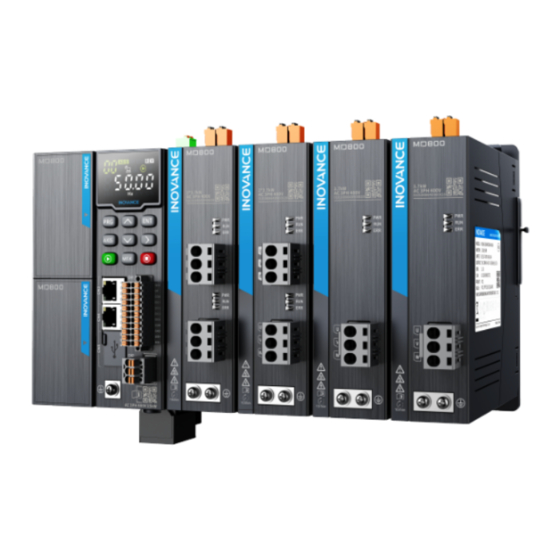
Preface Preface Introduction The MD800 series is a new generation of standard AC drive (multidrive system) designed for low‑power and multidrive applications in the traditional OEM industry. It is widely applied in industries such as printing and packaging, woodworking machine tools, food and beverage, logistics and warehousing, textile printing and dyeing, fans and pumps. - Page 3 This document is not delivered with the product. You can obtain the PDF version of this document by the following method: http://en.inovance.cn/ Log in to Inovance's website ( ), choose Support > Download, perform keyword search, and download the PDF file.
-
Page 4: Emergency Message And Ac Drive Faults
Vendor defined error code: The fault code of the AC drive. ● Fault Code The following table lists standard fault codes of the MD800 AC drive. For details about the fault codes, see the MD800 Series Multidrive AC Drive Maintenance Guide. - Page 5 Emergency Message and AC Drive Faults Table –2 Fault code of the drive unit AC Drive Fault Information AC Drive Fault Information 0000: No fault 0001: Hardware fault 0002: Overcurrent during acceleration 0015: EEPROM read‑write fault 0003: Overcurrent during deceleration 0016: Motor auto‑tuning error 0004: Overcurrent during operation at 0017: Motor shorted to the ground...
-
Page 6: Table Of Contents
Table of Contents T T a a b b l l e e o o f f C C o o n n t t e e n n t t s s Preface ................1 Emergency Message and AC Drive Faults. - Page 7 Table of Contents 4.4 Networking Topology............65 4.5 PZD Data .
-
Page 8: Parameter Communication Address
Parameter Communication Address Parameter Communication Address Parameter Data Parameters of the AC drive include basic function parameters and monitoring function parameters. They are stored in corresponding parameter groups. Basic function parameters are stored in groups F and A, as shown in the following table. Parameter Data Group F (read‑... -
Page 9: Modbus-Specific Parameter Communication Addresses
Parameter Communication Address Parameter Group No. Communication Access Modified RAM Parameter Address Address Through Communication F0 to FE 0xF000 to 0xFEFF 0x0000 to 0x0EFF A0 to AF 0xA000 to 0xACFF 0x4000 to 0x4CFF ‑ 0x7000 to 0x70FF ‑ 0x7300 to 0x73ff ‑... - Page 10 Parameter Communication Address Description Para. Address 7311H Control command 0: Stop by a stop method set in F6‑10 (Stop mode) input to AC drive 1: Forward run (write‑only) 2: Reverse run 3: Forward jog 4: Reverse jog 5. Coast to stop 6: Decelerate to stop 7: Fault reset 703DH...
- Page 11 Parameter Communication Address Description Para. Address 7312H DO control Bit0: DO1/RO1 output control Bit1: DO2/RO2 output control Bit2: DO3/RO3 output control Bit3: DO4/RO4 output control Bit4: DO5/RO5 output control Bit5 to bit15: Reserved ‑ ‑...
- Page 12 Parameter Communication Address Description Para. Address 8000H AC drive fault Power supply unit fault: description 12: Grid voltage abnormal 14: IGBT overtemperature 16: Communication error 21: EEPROM fault 61: Braking unit fault 80: Fan unit abnormal 98: Internal communication error 99: Extension card fault Drive unit fault: 1: Hardware fault...
-
Page 13: Station Number Allocation
Parameter Communication Address Station Number Allocation 1.4.1 Station Number Settings When AC drives are cascaded, Fd‑18 must be set. Figure 1‑1 System cascading topology Automatically Assigning Station Number 1. Set parameters Fd‑18 and Fd‑39 of each power supply unit as appropriate. By default, Fd‑18 is set to 1 and Fd‑39 is set to 0 (auto mode). - Page 14 Parameter Communication Address Figure 1‑2 Current station number of device 1 Figure 1‑3 Current station number of device 2 Manually Setting Station Number 1. Set parameters Fd‑18 and Fd‑39 of each power supply unit as appropriate. By default, Fd‑18 is set to 1 and Fd‑39 is set to 0 (auto mode). Set Fd‑18 to the number of the power supply unit.
- Page 15 Parameter Communication Address Para. Name Value of AC Value of AC Drive 1 Drive 2 Fd‑18 Number of the power supply unit Fd‑39 Station number setting mode Fd‑40 Manual setting of power supply unit station number Fd‑41 Manual setting of drive unit 1 station number Fd‑42 Manual setting of drive unit 2...
-
Page 16: Parameters
Parameter Communication Address No station number conflict will occur in this mode. Station number conflicts between cascaded AC drives cannot be detected. Manual assign mode ● An alarm is triggered in the case of duplicate station numbers in one group. Station number conflicts between cascaded AC drives cannot be detected. - Page 17 Parameter Communication Address Para. Name Value Meaning Attribute Description Range Fd‑93 Station number of device The station Displays the station connected to extension card number of the number of the device slot 1 current slot connected to the current slot. This station number Fd‑94 Station number of device The station...
-
Page 18: Modbus Communication
Modbus Communication Modbus Communication Communication Overview The AC drive is provided with RS485 communication interfaces and can serve as a communication slave in a PC/PLC control network that includes one master and multiple slaves. You can use a computer or PLC to implement centralized control, such as setting operation commands, modifying or reading parameters, and reading running state and fault information of the AC drive. -
Page 19: Communication Transmission Mode
Modbus Communication Figure 2‑2 Modbus communication interface Transmission Distance The maximum allowable number of nodes and transmission distance of a standard RS485 circuit vary with transmission rates, as listed in the following table. Table 2–1 Maximum number of nodes and transmission distance Transmission Rate (kbps) Number of Nodes... -
Page 20: Communication Data Frame Structure
Modbus Communication The AC drive adopts the Modbus‑RTU slave communication protocol, which allows the AC drive to provide data to respond to query commands from the master or execute actions according to query/commands from the master. The master can be a PC, an industrial control device, or a PLC. The master can communicate with a single slave or send broadcast messages to all slaves. - Page 21 Modbus Communication Multi‑write is the same as multi‑read and up to 12 parameters can be continuously written. If the slave detects a communication frame error or read/write failure due to other causes, the slave returns a frame of error. Note No response is returned for CRC check error.
- Page 22 Modbus Communication Table 2–3 Data frame fields Frame header (START) Idle time greater than 3.5‑byte transmission time Slave address (ADR) Communication address range: 1 to 247; 0 = Broadcast 03: Read slave parameters; 06: Write slave parameters; 10: Multi‑ Command code (CMD) write slave parameters Parameter address (H) Internal parameter address of the AC drive, expressed in...
- Page 23 Modbus Communication message. The receiving device recalculates a CRC value after receiving the message, and compares the calculated value with the CRC value in the received CRC field. If the two CRC values are unequal, a transmission error occurs. The CRC is first stored to 0xFFFF. Then a procedure is invoked to process the successive 8‑bit bytes in the message and the value in the register.
-
Page 24: Parameters
Modbus Communication return (crc_value); Definition of communication parameter addresses: R/W parameter (some parameters cannot be modified as they are manufacturer‑ specific parameters or for monitoring purpose only.) Parameters Modbus communication parameters are set on the power supply unit. Table 2–4 Modbus communication parameters Para. -
Page 25: Communication Configuration
2.6.1 Configuration for RS485 Communication Between AC Drive and H5U Software Acquisition and Hardware Wiring 1. Log in to Inovance website http://www.inovance.com/support/download.html to download the H5U programming software. 2. Connect the terminals RS485+ and RS485– of H5U to those of the AC drive, as shown below. - Page 26 Modbus Communication Master and Slave Configuration 1. Run AutoShop. On the page displayed, click " " N N e e w w P P r r o o j j e e c c t t " " , confirm that the value in the "...
- Page 27 Modbus Communication After finishing all write and read configurations, click " " O O K K " " to go back to the programming page. Example 1. Write frequency (F0‑03 set to 9) Data conversion: Multiply the required frequency value (a) by 100, convert the result into an integer, and then write the integer in 1000H.
- Page 28 Modbus Communication D300. Therefore, convert D300 to a floating‑point number and then divide the conversion result by 10. The configuration and procedure are as follows: 4. Read output voltage Based on the conversion rule, convert the output voltage U003 to 7003 and then the reading is the actual output voltage.
- Page 29 Modbus Communication 7. Read DI state Based on the conversion rule, convert the DI state U007 to 7007 and then convert the reading to a binary number, in which the least significant bit indicates DI1 status, the second least significant bit indicates DI2 status, and so on. 8.
-
Page 30: Configuration For Rs485 Communication Between Ac Drive And Am600
Modbus Communication Table 2–5 FAQ and Solutions Solution Failure to write Check the address in the configuration table based on F0‑03. frequency When F0‑03 is set to 0, the address should correspond to the value of F0‑08. When F0‑03 is set to 9, the address should be 1000H or 7310H. - Page 31 Modbus Communication The AC drive is provided with one set of RS485 port, which is on the CN1 connector ● of the power supply unit. Hardware connection procedure: 1. Taking COM1 as an example, connect one end of the LAN cable to CN1 of AM600 through DB9 and connect the RS485+, RS485–, and GND0 terminals of the other end to the RS485+, RS485–, and GND pins of the AC drive, as shown below.
- Page 32 Modbus Communication Configuration on AC Drive Side 1. Press the "AXIS" button on the AC drive and select the power supply unit from the commissioning station number. After the green characters "00" are displayed in the upper left corner of the AC drive display, press "PRG" to enter the parameter menu and set the parameters as follows: Fd‑00 to 5 Fd‑01 to 0...
- Page 33 Modbus Communication 2. Select StandardProjects under Categories, select AM600‑CPU1608TP/TN from the Devices section, select Structured Text (ST) from Language, set the project name and storage path, and then click " " O O K K " " . 3. Click " " L L o o c c a a l l B B u u s s C C o o n n f f i i g g " " and then click to select a CPU module. In hardware connection, COM0 is connected to MD800 through the RS485 cable.
- Page 34 Modbus Communication 5. Double‑click " " N N e e t t w w o o r r k k C C o o n n f f i i g g u u r r a a t t i i o o n n " " on the left. Double‑click the MODBUS option in the menu of Serial Port >...
- Page 35 Modbus Communication 8. Add the configuration on the "Modbus Slave Communication Configuration" page. 9. In the window displayed, configure the register information. Set the read address, write address, and frequency address of the control word of the AC drive to 3000H, 2000H, and 1000H, respectively.
- Page 36 Modbus Communication 10. On the Internal I/O Mapping page, map the PLC variables to the AC drive address. 11. Select the variable to be mapped. 12. Check whether the compiled program has an error. If not, log in to the PLC and download the program, and then click to run the program.
- Page 37 Modbus Communication ‑ ‑...
-
Page 38: Canopen And Canlink Communication
The CANlink communication protocol is a special protocol based on the CAN bus application and independently developed by Inovance. This protocol can be only used for communication with Inovance's PLCs such as H2U, H3U, and H5U. Communication Model CANopen is an application layer protocol of network transmission system based on the CAN serial bus. - Page 39 CANopen and CANlink Communication Supports emergency objects. ● Supports the synchronous mode. ● Object Dictionary An object dictionary is an ordered set of parameters and variables, and includes all parameters of the device profile and device network state. A set of objects can be accessed by using the ordered pre‑defined method.
- Page 40 CANopen and CANlink Communication RPDO4 — 0x500+Node‑ID TPDO1 — 0x180+Node‑ID TPDO2 — 0x280+Node‑ID TPDO3 — 0x380+Node‑ID TPDO4 — 0x480+Node‑ID EMCY object: 0x80+Node‑ID ● Node‑ID: Device ID (station address) set by Fd‑13. Communication objects are defined as follows: ● A network management object (NMT) includes Boot‑up messages, Heartbeat protocol, and NMT messages.
- Page 41 CANopen and CANlink Communication is a command word occupying one byte, as shown in " Table 3–2 NMT packet command format " on page 40 . Data1 is a CANopen network device address occupying one byte. When it is "0", it indicates a broadcast message that is sent to all slave devices in the network For example, to set a device with device address "6"...
-
Page 42: Networking And Interfaces
CANopen and CANlink Communication Table 3–5 NodeGuarding return status Data Bit Description Bit7 "0" or "1" must be alternatively set every time. State: Bit6 to bit0 4: Stopped 5: Operational 127: Pre‑operational Heartbeat packet ● The nodes can be configured to periodically generate Heartbeat packets. The status word bit7 is "0"... - Page 43 CANopen and CANlink Communication Figure 3‑4 CANopen/CANlink communication terminals Table 3–7 CN3 terminal pins Code Name Arrangement CANH H terminal for CAN communication CANL L terminal for CAN communication CGND Grounding terminal for CAN communication Reserved Reserved Reserved Reserved Reserved Reserved Reserved Reserved...
-
Page 44: Parameters
CANopen and CANlink Communication Transmission Distance The transmission distance of CANopen/CANlink bus is directly dependent on the baud rate and communication cable. The mapping between the maximum transmission distance of the bus and the baud rate is described in the following table. Table 3–9 Baud rate and bus length Baud Rate (bps) Length (m) - Page 45 CANopen and CANlink Communication Value Range Description Para. No. Name Default This parameter defines whether to enable the CANopen mode. 0: Disabled When it is set to 0, ordinary mode is CANopen402 selection Fd‑11 1: Enabled selected. When it is set to 1, CIA402 mode is selected.
-
Page 46: Application
CANopen and CANlink Communication Value Range Description Para. No. Name Default 0: Standard mode This parameter defines the CANopen CANopen mode Fd‑34 1: Expert mode mode. This parameter defines the CANopen CANopen inhibit time Fd‑35 0 to 65535 inhibit time. This parameter defines the CANopen CANopen event time Fd‑36... -
Page 47: Operation Example (Sdo)
CANopen and CANlink Communication The sub‑index is the lower 16 bits of a parameter address plus 1, so the correspondence between the parameter group numbers and the object dictionary sub‑indexes is as follows: Table 3–12 Correspondence between the parameter group numbers and the object diction‑ ary sub‑indexes Parameter Index CANopen Object Dictionary Index... - Page 48 CANopen and CANlink Communication Table 3–14 SDO object returned for read operation CAN Frame CANopen Data Description COB‑ID 11‑bit ID 0x580+Node‑ID Node‑ID is determined by dial switch setting.. Remote frame flag "0" DATA0 Success: "0x4B" 8‑byte frame data Command code return Failure: "0x80"...
- Page 49 CANopen and CANlink Communication If the operation fails, the command code return value is "0x80"; the index remains unchanged; SDO failure error codes are returned in DATA4, DATA5, DATA6, and DATA7. Table 3–16 SDO object returned for write operation CAN Frame CANopen Data Description COB‑ID...
-
Page 50: Operation Example (Pdo)
CANopen and CANlink Communication Table 3–19 Packet sent from the master for writing F0‑02 Packet ID (Hex) Data (Hex) 0x606 2BF0200300000000 8. The following table shows the CANopen response packet from the AC drive. F0‑02 is rewritten as "0", that is, the current command source is set to the operating panel. Table 3–20 AC drive response to the request of writing F0‑02 Packet ID (Hex) Data (Hex) - Page 51 CANopen and CANlink Communication RPDO TPDO Group AF Address Group AF Address AF‑48 RPDO3 Sub‑index 1 AF‑16 TPDO3 Sub‑index 1 AF‑17 AF‑49 AF‑18 AF‑50 Sub‑index 2 Sub‑index 2 AF‑19 AF‑51 AF‑20 AF‑52 Sub‑index 3 Sub‑index 3 AF‑21 AF‑53 AF‑22 AF‑54 Sub‑index 4 Sub‑index 4 AF‑23...
-
Page 52: Communication Configuration
3.5.1 Configuration for CANlink Communication Between AC Drive and Software Acquisition and Hardware Wiring 1. Log in to Inovance website http://www.inovance.com/support/download.html to download the H5U programming software. 2. Connect one registered jack of a standard LAN cable to the CN3/4 port of the power supply unit of the AC drive and connect the other end to H5U. - Page 53 CANopen and CANlink Communication Baud Rate: Upon computer setting (the baud rate of CAN communication for PLC initialization must be the same as that of the AC drive) 3. Click and then click " " A A d d d d C C A A N N C C o o n n f f i i g g " " . Next, double‑click "...
- Page 54 CANopen and CANlink Communication Example 1. Write frequency (F0‑03 set to 9) Data conversion: Multiply the required frequency value (a) by 100, convert the result into an integer, and then write the integer in 1000H. The configuration and procedure are as follows: 2.
- Page 55 CANopen and CANlink Communication 4. Read output voltage Based on the conversion rule, convert the output voltage U003 to 7003 and then the reading is the actual output voltage. Based on the communication configuration, you can move or not move the D302 value to another D element. The configuration and procedure are as follows: 5.
- Page 56 CANopen and CANlink Communication The configuration and procedure are as follows: 8. Read fault code Based on the conversion rule, convert the fault code U045 to 702D and fault sub‑ code U046 to 702E. The configuration and procedure are as follows: FAQ and Solutions Items must be checked: 1.
-
Page 57: Configuration For Canopen Communication Between Ac Drive And H5U
3.5.2 Configuration for CANopen Communication Between AC Drive and Software Acquisition and Hardware Wiring 1. Log in to Inovance website http://www.inovance.com/support/download.html to download the H5U programming software and the latest EDS file. 2. Connect one registered jack of a standard LAN cable to the CN3/4 port of the power supply unit of the AC drive and connect the other end to H5U. - Page 58 CANopen and CANlink Communication Master and Slave Configuration 1. Run AutoShop. On the page displayed, click " " N N e e w w P P r r o o j j e e c c t t " " , confirm that the value in the "...
- Page 59 In this step, you need to map the PDO data (the read or written data) to exchange the data between the PLC and the AC drive through the D element. Inovance H5U is a high‑performance compact PLC that automatically performs I/O mapping based on the configured PDO.
- Page 60 CANopen and CANlink Communication Assign a value for the D element corresponding to the control word of the required station number to enable the AC drive to run forward or backward or stop. The control word is defined as follows: 1: Forward run 2: Reverse run 3: Forward jog 4: Reverse jog 5: Coast to stop 6: Decelerate to stop 7: Fault reset The procedure is as follows:...
- Page 61 CANopen and CANlink Communication 6. Read AC drive state Based on the I/O mapping, read D7426 to get the current state of the AC drive (1: Forward running; 2: Reverse running; 3: Stop). The procedure is as follows: 7. Read DI state Based on the conversion rule, convert the DI state to D7410 according to the I/O mapping and then convert the reading to a binary number, in which the least significant bit indicates DI1 status, the second least significant bit indicates DI2...
-
Page 62: Communication Error
CANopen and CANlink Communication 3. Check whether the CAN communication baud rate of the power supply unit (set through Fd‑12) is the same as that of the PLC. 4. Check whether the Fd‑13 (CAN station number) setting of the current AC drive is unique from that of other AC drives are the same. - Page 63 CANopen and CANlink Communication Diagnostic If the displayed value is greater than 0 and does not increase, it is indicated that the network once suffered strong interference for a long time. If the displayed value is greater than 0 and increases within 5 minutes, it is indicated that the network is suffering interference or the configuration is inappropriate.
-
Page 64: Profinet Communication
In this guide, the PN card software version must be 33.01 or later. After the PN card is installed and the AC drive is powered on, query the parameter Fd‑91 of the power supply unit. The GSDML file is GSDML‑V2.31‑inovance‑MD800PNGATE‑20201229.xml. Installing Power off the AC drive, wait for about 10 minutes until the charging indicator of the AC drive is completely turned off, and then install the PN card. - Page 65 PROFINET Communication Ethernet pins. They can be connected using crossover cables or straight‑through cables. Table 4–1 Description of PN card terminals Description Terminal Code Terminal Name Port1 Network port 1 When the topology is not configured, any terminal can be connected to the Port2 Network port 2 PLC.
-
Page 66: Networking Topology
PROFINET Communication Networking Topology After communication between the PN card and the AC drive is implemented, you can connect the AC drive to the PROFINET master station and configure related parameters to implement communication between the PN card and the PROFINET master station, thereby implementing AC drive networking. -
Page 67: Pzd Data
PROFINET Communication Figure 4‑4 Tree topology PZD Data The PZD data is used for the master station to modify and read AC drive data in real time and perform periodic data exchange. It is mainly used to: 1. Set AC drive control command and target frequency in real time. 2. - Page 68 PROFINET Communication Table 4–3 Interaction data PZD of Data Sent by the Master Station PZD of AC Drive Response PZD1 PZD2 PZD3 to PZD1 PZD2 PZD3 to PZD16 PZD16 Frequency Operation Control word Modifying Status word Reading reference (U3‑17) (U0‑68) frequency function function...
-
Page 69: Parameters
PROFINET Communication Parameters PN Card Setting of AC Drive After the PN extension card is inserted to the AC drive, you must set Fd‑10 to 3 and restart the AC drive before enabling the PN communication card mode. Value Range Setpoint Description Para. -
Page 70: Communication Configuration
If the slave station devices have been added to the master station system, skip this step. Contact Inovance agents or vendors to get the GSDML file. If the 200 SMART ST&SR series master station is used, the PLC firmware version must be 2.05 or later. - Page 71 PROFINET Communication c. Click "Add new device". d. On the page displayed, select the PLC and its firmware version based on the article No. Click "Add" or double‑click the master station. The master station is created. Note: The selected PLC must match the article No. Otherwise, the PLC cannot be downloaded.
- Page 72 PROFINET Communication 2. Install the GSD file (if you never install GSDML, perform this step). a. In the "Options" drop‑down list, select "Manage general station description files (GSD)". b. Select the GSDML storage path (Note: The GSDML file cannot be stored in a path containing Chinese characters.
- Page 73 PROFINET Communication In the dialog box prompting that the GSDML is installed, click "Close". 3. Create a network a. Click "Device configuration" on the page and then switch to the "Network view". b. Select the Ethernet port of the PLC, choose "Properties" > "General", and set the IP address and subnet mask of the PLC master station.
- Page 74 PROFINET Communication c. In the "Hardware catalog" section on the right, locate MD800 and then double‑ click MD800PN. d. Click "Not assigned" and select the master station system to which the slave station needs to connect. e. Select the slave station, choose "Properties" > "General". Under "PROFINET interface [X1]", select "Ethernet addresses", and then set the IP address.
- Page 75 PROFINET Communication f. On the preceding page, drag the scroll bar to the "PROFINET" section, deselect "Generate PROFINET device name automatically". Input the name of the slave station in the "PROFINET device name" field. You can also select "Generate PROFINET device name automatically" and then the system automatically generates the device name.
- Page 76 PROFINET Communication a. Add a slave station Select the slave station and switch to "Device view". In the "Module" list under "Catalog", two modules are available: Rectifier Device and MD800 Device. Double‑click a module to add the module to the "Device overview" list. b.
- Page 77 PROFINET Communication c. Configure the process data Select a module from the "Device overview" list. In the list of "Submodules" under "Catalog", three catalogs are available: Empty, Input, and Output, which are used to configure the process data length for the module. In the "Output" catalog, set the length of the master‑to‑slave process data.
- Page 78 PROFINET Communication address), compile the project, click "Download" to download the generated file, select an interface, and then click "Start search". e. Assign a name for the device 1). After the project is downloaded, you need to assign a name for the slave station.
- Page 79 PROFINET Communication When information in the following figure is displayed, the device name is written and consistent with that in the " Configured PROFINET device" section in the preceding figure. After assignment, close the page or select another name from the drop‑down list of "PROFINET device name" to assign a name for another site.
-
Page 80: Mrp Function And Configuration
PROFINET Communication 4.7.2 MRP Function and Configuration MRP Overview The AC drive adopts the standard Media Redundancy Protocol (MRP) that meets the IEC62439‑2 standard. It provides a typical reconstruction time of 200 ms and supports up to 50 devices in each ring network. MRP basic rules: 1. - Page 81 PROFINET Communication 3. MRP provides a typical reconstruction time of 200 ms and supports up to 50 devices in each ring network. To avoid interference to PROFINET communication during ring network reconstruction, set the PROFINET watchdog time of the I/O device to be greater than 200 ms.
-
Page 82: Troubleshooting
PROFINET Communication Troubleshooting 4.8.1 Communication Fault Code When the communication function is incorrectly configured, the PLC and power supply unit operating panel report errors. You can view error messages for troubleshooting. The power supply unit may report the following errors: ‑81‑... -
Page 83: Plc Diagnosis Information
PROFINET Communication Table 4–5 Fault code of the power supply unit Fault Possible Cause Solution Reset Mode Code E16.71 The communication Check whether the connection between the When Fd‑06 is set to 1, between the PN card communication card and PLC is in poor contact. Make auto reset is performed. - Page 84 PROFINET Communication ‑83‑...
-
Page 85: Ethercat Communication
EtherCAT Communication EtherCAT Communication Overview The EtherCAT communication card (hereinafter referred to as the ECAT card) supports the super‑high‑speed I/O network for industrial field application. The protocol can be used to directly process data at the I/O layer. It features high efficiency, flexible topology, and ease‑to‑use. -
Page 86: Hardware Layout
EtherCAT Communication Hardware Layout Figure 5‑1 Arrangement of ECAT card terminals The ECAT card is connected to the EtherCAT master station by using the standard Ethernet RJ45 socket. Its pin signal definitions are the same as those of the standard Ethernet pins. - Page 87 EtherCAT Communication Table 5–2 Description of ECAT card indicator Indicator Status Description Solution None RUN/ERR Steady ON in The communication is green normal. Steady ON in The communication Check whether the connector between the ECAT card has interference. and a node times out. Flicker slowly The communication 1.
-
Page 88: Networking Topology
EtherCAT Communication Networking Topology After communication between the ECAT card and the AC drive is implemented, you can connect the AC drive to the ECAT master station and configure related parameters to implement communication between the ECAT card and the ECAT master station, thereby implementing AC drive networking. -
Page 89: Pdo Data
EtherCAT Communication Figure 5‑4 Tree topology PDO Data Description of PDO Data The PDO data is used for the master station to modify and read AC drive data in real time and perform periodic data exchange. Data communication addresses are directly configured by the AC drive. - Page 90 EtherCAT Communication Master‑Axis 2 Sending PDO (1602h) Corresponding Data PDO (1A02h) of AC Drive Axis 2 Fixed RPDO Variable RPDO AC drive AC drive target Modifying function AC drive state AC drive operation Reading function command frequency parameters of AC frequency parameters of AC drive in real time...
- Page 91 EtherCAT Communication Master‑Axis 8 Sending PDO (1608h) Corresponding Data PDO (1A08h) of AC Drive Axis 8 Fixed RPDO Variable RPDO AC drive AC drive target Modifying function AC drive state AC drive operation Reading function command frequency parameters of AC frequency parameters of AC drive in real time...
-
Page 92: Sdo Data
EtherCAT Communication AC Drive Response Data Table 5–4 TPDO of ac drive response data RPDO Description TPDO1 AC drive running state AC drive running state is determined by the bits as follows: Bit0: 0: AC drive stop; 1: AC drive running Bit1: 0: Forward running;... - Page 93 EtherCAT Communication Table 5–5 Parameters of power supply unit Para. Value Range Setpoint Description Name If it is set to 1, CANopen 1: CANopen communication is selected. If 2: CANlink it is set to 2, CANlink Communication Fd‑10 communication is selected. f protocol selection Communica it is set to 3, the...
- Page 94 EtherCAT Communication Para. Value Range Setpoint Description Name EtherCAT state State machine and PHYLink Fd‑81 machine and 0 to 65535 status PHYLink status 0: No error 1 to 0xFFFF: EtherCAT AL fault Fd‑82 AL fault code Error state code code EtherCAT XML file 0.00 to Fd‑83...
- Page 95 EtherCAT Communication Table 5–6 Parameters of drive unit Para. Value Range Setpoint Description Name 0: Operating panel of the power supply For the drive unit, set Command source unit/LCD operating F0‑02 this parameter to 2. selection panel/Software tool 1: Terminal 2: Communication 0: Digital setting (preset frequency...
- Page 96 EtherCAT Communication Para. Value Range Setpoint Description Name CAN communication protocol display: Displays the communication protocol of the power supply unit. Switchover 1 means CANopen or 1: CANopen Fd‑10 between CANopen communication 2: CANlink and CANlink extension card mode. 2 means CANlink.
- Page 97 EtherCAT Communication Description Para. No. Index Sub‑index Bus voltage U0‑00 16#2170 16#01 Heatsink temperature U0‑01 16#2170 16#02 Fan speed U0‑03 16#2170 16#04 Common parameters of Input voltage Usr U0‑04 16#2170 16#05 the power Input voltage Ust U0‑05 16#2170 16#06 supply unit Input voltage Utr U0‑06 16#2170...
- Page 98 EtherCAT Communication Object Dictionary Index Object Dictionary Index Device Type Range of CANopen402 Range of I/O Device Protocol Drive unit axis 7 0x5000 to 0x50FF 0x9000 to 0x97FF Drive unit axis 8 0x5800 to 0x58FF 0x9800 to 0x9FFF When an MD800‑ECAT card is used, the written PDO1 and PDO2 are mapped to U3‑17 and U3‑16 respectively by default.
- Page 99 EtherCAT Communication Para. No. Name Unit Decimal Address Linear speed 1 m/min U0‑24 28696 Current power‑on U0‑25 1 min 28697 time Current running time 0.1 min U0‑26 28698 U0‑28 Communication 0.01% 28700 Display of main U0‑30 0.01 Hz 28702 frequency X Display of auxiliary U0‑31 0.01 Hz...
-
Page 100: Communication Configuration
U0‑01 respectively by default. Communication Configuration 5.8.1 Configuration for EtherCAT Communication Between AC Drive and Software Acquisition and Hardware Wiring 1. Log in to Inovance website http://www.inovance.com/support/download.html to download the H5U programming software and the latest XML file. ‑99‑... - Page 101 EtherCAT Communication 2. Use a standard network cable to connect the EtherCAT RJ45 interface of H5U to the EC IN port on the EtherCAT card of the AC drive. Master and Slave Configuration 1. Run AutoShop. On the page displayed, click " " N N e e w w P P r r o o j j e e c c t t " " , confirm that the value in the "...
- Page 102 EtherCAT Communication Groups A0 to AF: Convert the high bit A to 4 and then add 0X2000. Groups U0 to UF: Convert the high bit U to 7 and then add 0X2000. Sub‑index: Convert the decimal number of the lower 16 bits to a hexadecimal value and then add 1 to the conversion result.
- Page 103 EtherCAT Communication Example 1. Write frequency (F0‑03 set to 9) Based on the I/O mapping, you need to assign a value for DO. The procedure is as follows (equivalent to writing a data to the address 1000H in RS485 communication mode): 2.
- Page 104 EtherCAT Communication Based on the conversion rule, convert the output voltage U003 to 2070sub4 and then the reading is the actual output voltage. Based on the communication configuration, you can move or not move the D302 value to another D element. 5.
-
Page 105: Example Of Configuration On Beckhoff Controller Using Ecat Card
EtherCAT Communication FAQ and Solutions Items must be checked: Check whether Fd‑10 is set to 3 for the power supply unit and to 1 for the drive unit. Table 5–11 FAQ and Solutions Solution Failure to write Check the address in the configuration table based on F0‑03. frequency Check whether the termination resistor is connected. - Page 106 EtherCAT Communication TwinCAT2 directory: TwinCAT\IO\EtherCAT. TwinCAT3 directory: TwinCAT\3.1\config\IO\EtherCAT. The following takes TwinCAT3 as an example. TwinCAT2 can be configured in the same way as TwinCAT3. 3. Run TwinCAT. a. Click "New Project". b. Click "OK". A new project is created. 4.
- Page 107 EtherCAT Communication Access the menu "Show Real Time Ethernet Compatible Devices…" in the preceding figure. In the dialog box displayed, select the local device from the "Incompatible devices" field, and then click "Install". Then, the network card is installed and displayed in the "Installed and ready to use devices" column, as shown below.
- Page 108 EtherCAT Communication c. Click "OK". d. Click "Yes". e. Click "OK". f. Click "No". Then, the device searching is finished. 6. Configure the PDO parameters. This AC drive has multiple axes. When configuring the PDO parameters, match each TPDO and RPDO with the corresponding axis. a.
- Page 109 EtherCAT Communication b. Configure TPDO. When you configure TPDO, 0x1A01 (Axis 1) is selected by default. The first two items are the default TPDOs, which can be modified as needed. Right‑click the arrow position in the figure and add the required TPDO mapping. c.
- Page 110 EtherCAT Communication 7. Configure the SDO list (not supported now). 8. Activate the configuration and switch the mode to OP. a. Click . The following page is displayed. b. Click "OK". c. Click "OK". The current state changes to OP. ‑109‑...
- Page 111 EtherCAT Communication 9. Set PDO to control the AC drive operation mode. Write a corresponding value to RPDO to control the AC drive operation mode. ‑ ‑...
-
Page 112: Example Of Configuration On Am600 Master Station Using Ecat Card
EtherCAT Communication 5.8.3 Example of Configuration on AM600 Master Station Using ECAT Card The following takes the AM600 master station as an example to describe how to configure the AC drive to work with the master station. 1. Run the software and create an AM600 project. Select "AM600‑CPU1608TP/TN"... - Page 113 EtherCAT Communication b. Select a device from "Network Devices List" and add it as an AC drive slave station through drag‑and‑drop. 3. Configure the PDO parameters. a. Right‑click the arrow position in the figure and add the required TPDO mapping. The control command of RPDO and inverter state of TPDO can be modified.
-
Page 114: Example Of Configuration On Omron Master Station Using Ecat Card
EtherCAT Communication 5.8.4 Example of Configuration on Omron Master Station Using ECAT Card The following takes the Omron NX701‑1600 master station as an example to describe how to configure the AC drive to work with the master station. 1. Copy the XML file of this product to the installation directory "E:\OMRON\Sysmac Studio\IODeviceProfiles\EsiFiles\UserEsiFiles"... - Page 115 EtherCAT Communication 4. Scan the device. a. Switch the controller status to ONLINE and RUN mode. The controller status is displayed in the lower right corner. b. Scan the device and add a slave station. Choose "Configurations and Setup" > "EtherCAT". Right‑click "Master" and select "Compare and Merge with Actual Network Configuration".
- Page 116 EtherCAT Communication 5. Configure the parameters. a. Change the controller status to OFFLINE, select this device, and click "Edit PDO Map Settings". ‑115‑...
- Page 117 EtherCAT Communication b. On the "Edit PDO Map Settings" page displayed, select the axis number to be configured and right‑click in the blank area on the right, and then click "Add PDO Entry" or "Delete PDO Entry" to add or delete a PDO entry. When adding a PDO entry, you must select the entry corresponding to the specific axis.
- Page 118 EtherCAT Communication c. Set the PDO mapping (assign the I/O mapping). 6. Edit the PLC program. ‑117‑...
- Page 119 EtherCAT Communication 7. Download the PLC program to the controller. a. After finishing the configuration and programming, change the controller status to ONLINE, click "Execute" and then download the program to the controller. b. After the PLC program is run, access "I/O Map", and the real‑time data is displayed.
-
Page 120: Troubleshooting
EtherCAT Communication Troubleshooting 5.9.1 ECAT Card Communication Error All communication fault codes are displayed on the power supply unit operating panel. ‑119‑... - Page 121 EtherCAT Communication Table 5–12 ECAT card communication fault codes Fault Code Possible Cause Solution Reset Mode E16.52 The EEPROM of the When Fd‑06 is set to 1, auto 1. If the programming or upgrading of the EtherCAT reset is performed. communication card fails, program the communication card When Fd‑06 is set to 0, you need...
- Page 122 *19011496A01*...
Need help?
Do you have a question about the MD800 Series and is the answer not in the manual?
Questions and answers