Inovance MD500-PLUS Series Hardware Manual
General-purpose ac drive
Hide thumbs
Also See for MD500-PLUS Series:
- Software manual (718 pages) ,
- Hardware manual (175 pages) ,
- Installation manual (173 pages)
Table of Contents
Advertisement
Advertisement
Table of Contents

Subscribe to Our Youtube Channel
Related Manuals for Inovance MD500-PLUS Series


Summary of Contents for Inovance MD500-PLUS Series
-
Page 2: Preface
Preface Preface Introduction The MD500‑PLUS series AC drive is a general‑purpose high‑performance current vector control AC drive designed to control and regulate the speed and torque of three‑phase AC asynchronous motors and permanent magnet synchronous motors. It can be used to drive textile machines, paper machines, wire drawing machines, machine tools, packaging machines, food machines, fans, water pumps, and other automated production equipment. - Page 3 This guide is not delivered with the AC drive. You can obtain the PDF version of this document using the following method: http://en.inovance.cn/ Log in to Inovance's website ( ), choose Support > Download, perform keyword search, and download the PDF file.
-
Page 4: Table Of Contents
Table of Contents T T a a b b l l e e o o f f C C o o n n t t e e n n t t s s Preface ................1 AC Drive Models . - Page 5 Table of Contents 5.4.2 AC Input Reactor ............74 5.4.3 EMC Filter .
-
Page 6: Ac Drive Models
AC Drive Models AC Drive Models The following table lists the relationship between the AC drive model and structure. Table –1 Relationship between the AC drive model and structure AC Drive Model (Three‑phase AC Drive Model (Three‑phase AC Drive Model (Single‑ Structure 380 V to 480 V) 200 V to 240 V) - Page 7 AC Drive Models AC Drive Model (Three‑phase AC Drive Model (Three‑phase AC Drive Model (Single‑ Structure phase 200 V to 240 V) 380 V to 480 V) 200 V to 240 V) MD500T500G/630P‑PLUS T13 (without auxiliary MD500T560G/710P‑PLUS ‑ ‑ power distribution cabinet) MD500T630G/800P‑PLUS MD500T500G/630P‑A‑PLUS T13 (with auxiliary power...
-
Page 8: Fundamental Safety Instructions
3. Use this equipment according to the designated environment requirements. Damage caused by improper use is not covered by warranty. 4. Inovance shall take no responsibility for any personal injuries or property damage caused by improper use. Safety Levels and Definitions Indicates that failure to comply with the notice will result in death or severe personal injuries. - Page 9 Fundamental Safety Instructions Check whether the packing is intact and whether there is damage, water seepage, ● dampness, and deformation before unpacking. Unpack the package by following the unpacking sequence. Do not strike the package ● violently. Check whether there is damage, rust, or injuries on the surface of the equipment and ●...
- Page 10 Fundamental Safety Instructions Read through the guide and safety instructions before installation. ● Do not install this equipment in places with strong electric or magnetic fields. ● Before installation, check that the mechanical strength of the installation site can bear ●...
- Page 11 Fundamental Safety Instructions Do not connect the input power supply to the output end of the equipment. Failure to ● comply will result in equipment damage or even a fire. When connecting a drive to the motor, check that the phase sequences of the drive and ●...
- Page 12 Fundamental Safety Instructions Do not touch the equipment casing, fan, or resistor with bare hands to feel the ● temperature. Failure to comply may result in personal injuries. Prevent metal or other objects from falling into the equipment during operation. Failure ●...
- Page 13 Fundamental Safety Instructions Disposal Dispose of retired equipment in accordance with local regulations and standards. ● Failure to comply may result in property damage, personal injuries, or even death. Recycle retired equipment by observing industry waste disposal standards to avoid ●...
-
Page 14: Product Information
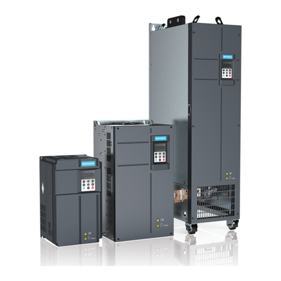
Product Information Product Information Features The MD500‑PLUS series AC drive is a general‑purpose high‑performance current vector AC drive used to control the speed and torque of three‑phase AC asynchronous motors and three‑phase AC permanent magnet motors. Figure 1‑1 Appearance The AC drive is armed with the following features: 1. -
Page 15: Nameplate And Model Number
Product Information 5. Upgraded based on MD500, MD500E, MD290, and MD330 series AC drives and compatible with MD500 series AC drive options, including the PG card, communication card, I/O extension card, and bracket. Nameplate and Model Number Figure 1‑2 Nameplate and designation rules ‑... - Page 16 Product Information Note For three‑phase 380 V to 480 V AC drives, reactors are not available for T1 to T4 ● models, while DC reactors are optional for T5 models and standard for T6 models. For three‑phase 380 V to 480 V AC drives, braking units are standard for T1 to T4 ●...
-
Page 17: Components
Components Components Overview The following types of enclosures are available for the AC drive: T1 to T6 models: plastic enclosure ● T7 to T13 models: sheet metal enclosure ● Components of T1 to T6 Models Figure 2‑1 Components of T1 to T4 models ‑... - Page 18 Components Figure 2‑2 Components of T5 to T6 models ‑17‑...
-
Page 19: Components Of T7 To T9 Models
Components Components of T7 to T9 Models Figure 2‑3 Components of T7 to T9 models Note The quantity and layout of cooling fans vary with models. T7 models have one cooling fan at the top. ● T8 models have two cooling fans at the top. ●... -
Page 20: Components Of T10 To T12 Models
Components Components of T10 to T12 Models Figure 2‑4 Components of T10 to T12 models (without AC output reactor) ‑19‑... -
Page 21: Components Of T13 Models
Components Figure 2‑5 Components of T10 to T12 models (with AC output reactor) Components of T13 Models T13 models are available in two structures: models with a standard cabinet and models with an auxiliary power distribution cabinet in addition to the standard cabinet. - Page 22 Components Figure 2‑6 Components of standard cabinet Figure 2‑7 Components of standard cabinet with auxiliary power distribution cabinet ‑21‑...
-
Page 23: System Structure
System Structure System Structure System Connection Diagram When the AC drive is used to control asynchronous motors to form a control system, a variety of electrical devices must be installed on the input and output sides of the AC drive to ensure system safety and stability. The following figure shows how to configure the AC drive. -
Page 24: Electrical Wiring Diagram
Braking resistor used to consume the regenerative energy during motor deceleration. Use a braking unit (MDBUN) or recommended braking resistor of Inovance for models not Braking unit containing letter B in the designation. The braking unit is used to consume the regenerative energy during motor deceleration. - Page 25 System Structure Figure 3‑2 Standard wiring Note For T1 to T8 (75 W) models (model number containing letter B) and T8 to T13 models (mod‑ el number without letter B), the connection indicated by the double‑headed arrow is different. ‑ ‑...
- Page 26 System Structure Figure 3‑3 Standard wiring (single‑phase 220 V) T13 models " Figure 3–2 " on page 24 " Figure 3–4 " shows the standard wiring of the cabinet, and on page 26 shows the electrical connection in the cabinet. ‑25‑...
-
Page 27: Main Circuit Terminals
System Structure Figure 3‑4 Electrical connection in the cabinet (T13 models) Main Circuit Terminals T1 to T9 models Figure 3‑5 Arrangement of main circuit terminals of T1 to T4 models ‑ ‑... - Page 28 System Structure Figure 3‑6 Arrangement of main circuit terminals of T5 to T8 models Figure 3‑7 Arrangement of main circuit terminals of T9 models Table 3–2 Main circuit terminals Description Terminal Name Three‑phase power supply Connected to AC input R, S, T input terminals three‑phase power supply.
- Page 29 System Structure T10 to T12 models Figure 3‑8 Arrangement of main circuit terminals of T10 to T12 models Table 3–3 Main Circuit Terminals Description Name Terminal Connected to AC input three‑ Three‑phase power supply input R, S, T phase power supply. terminals Common DC busbar input point, Positive and negative terminals...
- Page 30 System Structure T13 models Figure 3‑9 Arrangement of main circuit terminals of T13 models Table 3–4 Main Circuit Terminals Description Name Terminal Connected to AC input three‑ Three‑phase power supply input R, S, T phase power supply. terminals Common DC busbar input point, Positive and negative terminals +, ‑...
-
Page 31: Control Circuit Terminals
System Structure Control Circuit Terminals " Figure 3–10 " on page 30 shows the control circuit terminal arrangement. Figure 3‑10 Control circuit terminal arrangement ‑ ‑... - Page 32 System Structure Table 3–5 Description of control circuit terminals Terminal Item Terminal Name Function Code Provides +10 V power supply to an external unit. Its maximum output current is 10 mA. External +10 V Generally used to supply power to an +10V‑GND power supply external potentiometer with resistance...
- Page 33 System Structure Terminal Item Function Terminal Name Code Voltage or current output is selected by using the J4 jumper on the control board. Analog output 1 The maximum load resistance is 500 Ω. AO1‑GND Output voltage range: 0 V to 10 V Output current range: 0 mA to 20 mA Analog Output...
-
Page 34: Dimensions Drawings
Dimensions Drawings Dimensions Drawings T1 to T9 Models Figure 4‑1 Dimension drawing of T1 to T4 models Table 4–1 Dimensions of T1 to T4 models Mounting Hole Outline Dimensions Mounting Hole Weight mm (in.) mm (in.) Diameter Structure kg (lb) mm (in.) 119 (4.7) 189 (7.5) - Page 35 Dimensions Drawings Figure 4‑2 Dimension drawing of T5 to T6 models Table 4–2 Dimensions of T5 to T6 models Mounting Hole Outline Dimensions Mounting mm (in.) mm (in.) Hole Weight Structure kg (lb) Diameter mm (in.) T5 (without DC 195 (7.7) 335 (13.2) 350 (13.8) 210 (8.3)
- Page 36 Dimensions Drawings d x 4 Figure 4‑3 Dimension drawing of T7 to T9 models Table 4–3 Dimensions of T7 to T9 models Mounting Hole Outline Dimensions Mounting mm (in.) mm (in.) Hole Weight Structure kg (lb) Diameter mm (in.) 245 (9.7) 523 (20.6) 525 (20.7) 542 (21.4)
-
Page 37: T10 To T12 Models (Without Ac Output Reactor)
Dimensions Drawings T10 to T12 Models (Without AC Output Reactor) Figure 4‑4 Dimension drawing of T10 to T12 models (without AC output reactor) Table 4–4 Dimensions of T10 to T12 models (without AC output reactor) Mounting Mounting Hole Spacing Outline Dimensions Hole Weight mm (in.) -
Page 38: T10 To T12 Models (With Ac Output Reactor)
Dimensions Drawings T10 to T12 Models (with AC Output Reactor) Figure 4‑5 Dimension drawing of T10 to T12 models (with AC output reactor) Table 4–5 Dimensions of T10 to T12 models (with AC output reactor) Mounting Hole Mounting Hole Spacing Outline Dimensions Diameter Weight... -
Page 39: T13 Models (Without Auxiliary Power Distribution Cabinet)
Dimensions Drawings T13 Models (Without Auxiliary Power Distribution Cabinet) Figure 4‑6 Dimension drawing of T13 models (without auxiliary power distribution cabinet) ‑ ‑... - Page 40 Dimensions Drawings Table 4–6 Dimensions of T13 models (without auxiliary power distribution cabinet) Mounting Mounting Hole Spacing Outline Dimensions Hole Weight Struc‑ mm (in.) mm (in.) Diameter kg (lb) ture mm (in.) 73.5 1800 2100 15 (0.6) (26.0) (2.9) (17.7) (3.3) (4.9) (4.1)
-
Page 41: T13 Models (With Auxiliary Power Distribution Cabinet)
Dimensions Drawings T13 Models (with Auxiliary Power Distribution Cabinet) 4-ΦD1 A2 . Figure 4‑7 Dimension drawing of T13 models (with auxiliary power distribution cabinet) ‑ ‑... - Page 42 Dimensions Drawings Table 4–7 Dimensions of T13 models (with auxiliary power distribution cabinet) Hole Mounting Hole Spacing Outline Dimensions Dia. Wgt. mm (in.) mm (in.) kg (lb) (in.) 73.5 1800 2100 1205 15 (0.6) (1609. (26.0) (2.9) (10.2) (5.5) (17.7) (3.3) (5.2) (4.1)
-
Page 43: Options
Options Options List of Options Optional peripherals include braking units, function extension cards, and external operating panels. For use of each option, see the corresponding user guide. If any option is required, specify it in your order. Table 5–1 List of options Supported Description Device... - Page 44 Supports differential output and collector output and a variety of interfaces such as encoder interfaces and host controller A/B phase input interfaces. Supports Inovance 23‑bit 23‑bit PG card ES510–PG‑CT1 01320007 All models encoders and provides a DB9 interface.
- Page 45 Options Supported Description Device Model Order No. Models MD500‑AZJ‑A1T1 01040072 MD500‑AZJ‑A1T2 01040073 MD500‑AZJ‑A1T3 01040074 Satisfies requirements of MD500‑AZJ‑A1T4 01040075 Through‑hole through‑hole mounting. MD500‑AZJ‑A1T5 01040001 mounting bracket Applicable to T1 to T9 MD500‑AZJ‑A1T6 01040002 models only. MD500‑AZJ‑A1T7 01040003 MD500‑AZJ‑A1T8 01040004 MD500‑AZJ‑A1T9 01040005 MD500‑AZJ‑A2T1 01040085...
-
Page 46: Mounting Accessories
Options Supported Description Device Model Order No. Models External LED operating External LED operating MD32NKE1 01013061 All models panel panel The external LCD operating panel supports parameter External LCD operating copy and parameters MDKE9 01040037 All models panel display in Chinese or English. - Page 47 Options Models of Through‑hole Mounting Structure Brackets MD500‑AZJ‑A1T8 MD500‑AZJ‑A1T9 Mounting hole dimensions Figure 5‑1 Dimensions of MD500‑AZJ‑A1T1 through‑hole mounting bracket and mounting holes ‑ ‑...
- Page 48 Options Figure 5‑2 Dimensions of MD500‑AZJ‑A1T2 through‑hole mounting bracket and mounting holes ‑47‑...
- Page 49 Options Figure 5‑3 Dimensions of MD500‑AZJ‑A1T3 through‑hole mounting bracket and mounting holes ‑ ‑...
- Page 50 Options Figure 5‑4 Dimensions of MD500‑AZJ‑A1T4 through‑hole mounting bracket and mounting holes ‑49‑...
- Page 51 Options Figure 5‑5 Dimensions of MD500‑AZJ‑A1T5 through‑hole mounting bracket and mounting holes ‑ ‑...
- Page 52 Options Figure 5‑6 Dimensions of MD500‑AZJ‑A1T6 through‑hole mounting bracket and mounting holes ‑51‑...
- Page 53 Options Figure 5‑7 Dimensions of MD500‑AZJ‑A1T7 through‑hole mounting bracket and mounting holes ‑ ‑...
- Page 54 Options Figure 5‑8 Dimensions of MD500‑AZJ‑A1T8 through‑hole mounting bracket and mounting holes ‑53‑...
- Page 55 Options Figure 5‑9 Dimensions of MD500‑AZJ‑A1T9 through‑hole mounting bracket and mounting holes ‑ ‑...
-
Page 56: Bottom Mounting Bracket
AC drive, as shown in the following figures. A 600 mm cabinet is delivered with the AC drive. If you need an 800 mm cabinet, contact Inovance. Figure 5‑10 Dimensions of bottom mounting bracket for T10 models (mm) - Page 57 Options Figure 5‑11 Dimensions of bottom mounting bracket for T11 models (mm) Figure 5‑12 Dimensions of bottom mounting bracket for T12 models (mm) ‑ ‑...
-
Page 58: Guide Rail
Options Note The rail diagram applies to PS cabinets (800 x 600 or 800 x 800 (W x D) in mm). ● Dimensions inside the parentheses apply to standard PS cabinets with a depth of ● 800 mm. 5.2.3 Guide Rail For details of the guide rail, see Operation Instructions for MD500‑AZJ‑A3T10 Guide Rail . - Page 59 Options Dimension drawings Figure 5‑13 Dimension drawing of T1 models (with conduit box) ‑ ‑...
- Page 60 Options Figure 5‑14 Dimension drawing of T2 models (with conduit box) ‑59‑...
- Page 61 Options Figure 5‑15 Dimension drawing of T3 models (with conduit box) ‑ ‑...
- Page 62 Options Figure 5‑16 Dimension drawing of T4 models (with conduit box) ‑61‑...
- Page 63 Options Figure 5‑17 Dimension drawing of T5 models (with conduit box) ‑ ‑...
-
Page 64: Cables
PVC cables with copper conductors ● 40°C ambient temperature and 70°C cable surface temperature (Note: Contact ● Inovance for ambient temperatures above 40°C.) Symmetrical cables with copper‑braided shield ● If the recommended cables for peripheral equipment or options are not suitable for the product, contact Inovance. - Page 65 Options To satisfy the EMC requirements, use shielded cables. Shielded cables are classified into three‑conductor cables and four‑conductor cables, as shown in the following figure. If the shield of the three‑conductor cable cannot provide sufficient conductivity, add an independent PE cable. or use a four‑conductor cable that contains a PE conductor.
- Page 66 Options Recommended cables Table 5–4 Recommended cable specifications (three‑phase 380 V to 480 V) RST/UVW Grounding Cable Tightening Torque Structure Model Screw Cable Cable Cable Lug Cable Lug N·m Model Model (lb.in) MD500T0.4G/0.7PB‑PLUS 3 x 0.75 TNR0.75‑4 0.75 TNR5.5‑5 MD500T0.7G/1.1PB‑PLUS 3 x 0.75 TNR0.75‑4 0.75...
- Page 67 Options Table 5–5 Recommended cable specifications (three‑phase 380 V to 480 V) (UL‑compliant) RST/UVW Grounding Cable Cable Structure Model Screw Cable (AWG/ Cable Lug Cable Lug (AWG/ kcmil) Model Model mil) MD500T0.4G/0.7PB‑PLUS TLK2.5‑4 2 x 14 TLK2.5‑4 MD500T0.7G/1.1PB‑PLUS TLK2.5‑4 2 x 14 TLK2.5‑4 MD500T1.1G/1.5PB‑PLUS TLK2.5‑4...
- Page 68 Options Table 5–6 Recommended cable specifications (three‑phase 200 V to 240 V) RST/UVW Grounding Cable Structure Model Screw Cable Cable Lug Cable Lug Cable (mm Model Model MD500‑2T0.4G/0.7PB‑PLUS MD500‑2T0.7G/1.1PB‑PLUS 3 x 0.75 TNR0.75‑4 0.75 TNR0.75‑4 MD500‑2T1.1G/1.5PB‑PLUS MD500‑2T1.5G/2.2PB‑PLUS 3 x 1 TNR1.25‑4 TNR1.25‑4 MD500‑2T2.2G/3.7PB‑PLUS...
- Page 69 Options Table 5–8 Recommended cable specifications (single‑phase 200 V to 240 V) (UL‑compliant) Grounding Cable RST/UVW Structure Model Screw Cable Lug Cable (AWG) Cable (AWG) Cable Lug Model Model MD500‑2S0.4GB‑PLUS TLK2.5‑4 2 x 14 TLK2.5‑4 MD500‑2S0.7GB‑PLUS TLK2.5‑4 2 x 14 TLK2.5‑4 MD500‑2S1.5GB‑PLUS TLK2.5‑4...
- Page 70 Options Table 5–10 Appearance, models, and dimensions of GTNR series lugs (unit: mm) Crimping Model Tool GTNR1.5‑5 16.0 GTNR2.5‑4 18.0 GTNR2.5‑5 20.0 GTNR2.5‑6 10.2 20.0 GTNR4‑5 10.0 20.0 RYO‑8 GTNR4‑6 10.0 20.0 YYT‑8 RYO‑14 GTNR6‑5 10.0 23.0 GTNR6‑6 10.0 26.0 GTNR6‑8 12.0 26.0...
- Page 71 Options Crimping Model Tool GTNR120‑12 19.8 15.0 22.0 14.0 10.0 28.0 13.0 60.0 GTNR120‑16 19.8 15.0 22.0 16.0 10.0 28.0 17.0 64.0 GTNR150‑12 21.2 16.5 26.0 16.0 11.0 30.0 13.0 69.0 GTNR150‑16 21.2 16.5 26.0 16.0 11.0 30.0 17.0 69.0 RYC‑150 GTNR185‑16 23.5...
-
Page 72: Selection Of Control Circuit Cables
Options Model 240‑10 10.5 240‑12 12.8 240‑14 37.7 18.0 32.0 88.0 14.7 17.0 240‑16 16.7 240‑20 20.7 300‑10 10.5 300‑12 12.8 300‑14 28.0 23.0 41.0 18.0 37.0 97.0 14.7 17.0 300‑16 16.7 300‑20 20.7 5.3.2 Selection of Control Circuit Cables Note Connect the control circuit cables according to EN 60204‑1. - Page 73 Options To meet requirements of EN 61800‑5‑1 and UL61800‑5‑1, install a fuse and circuit breaker on the input side to prevent accidents caused by internal short circuit. The following tables list recommended fuses and circuit breakers made by Bussmann. Table 5–12 Recommended specifications of fuses, contactors, and circuit breakers (three‑phase 380 V to 480 V) Fuse Contactor...
- Page 74 Options Fuse Contactor Circuit Breaker (Bussmann, and UL‑compliant) Structure Model Rated Current (A) Rated Current (A) Rated Current (A) Model MD500T315G/400P‑PLUS 1400 170M6017 1000 MD500T315G/400P‑L‑PLUS MD500T355G/450P‑PLUS 1400 170M6017 1000 MD500T355G/450P‑L‑PLUS MD500T400G/500P‑PLUS 1400 170M6017 1000 1250 MD500T400G/500P‑L‑PLUS MD500T500G/630P‑PLUS 1400 A ‑ MD500T500G/630P‑A‑PLUS MD500T560G/710P‑PLUS 1600 A...
-
Page 75: Ac Input Reactor
To install an AC input reactor on models above 200 kW, ensure sufficient space is reserved in the cabinet for installing the reactor. Models and dimensions of Inovance AC input reactors Recommended models are listed in the following tables. ‑... - Page 76 Options Figure 5‑21 AC input reactor model Table 5–15 Recommended Inovance AC input reactors (three‑phase 380 V to 480 V) Inductance Applicable Reactor Loss (W) Structure Model (mH) MD500T0.4G/0.7PB‑PLUS MD‑ACL‑10‑5‑4T MD500T0.7G/1.1PB‑PLUS MD‑ACL‑10‑5‑4T MD500T1.1G/1.5PB‑PLUS MD‑ACL‑10‑5‑4T MD500T1.5G/2.2PB‑PLUS MD‑ACL‑10‑5‑4T MD500T2.2G/3PB‑PLUS MD‑ACL‑10‑5‑4T MD500T3.0G/3.7PB‑PLUS MD‑ACL‑10‑5‑4T MD500T3.7G/5.5PB‑PLUS...
- Page 77 MD500T560G/710P‑A‑PLUS MD500T630G/800P‑PLUS GH‑MVT634ZG‑L3 0.018 MD500T630G/800P‑A‑PLUS Note: T13 models containing "‑A" in the designation are delivered with an input reactor. Table 5–16 Recommended Inovance AC input reactors (three‑phase 200 V to 240 V) Applicable Reactor Inductance (mH) Loss (W) Structure Model MD500‑2T0.4G/0.7PB‑PLUS...
- Page 78 Options Applicable Reactor Inductance (mH) Loss (W) Structure Model MD500‑2T160G/200P‑PLUS MD‑ACL‑660‑0.021‑4T‑2% 0.021 ‑ MD500‑2T200G/220P‑PLUS MD‑ACL‑800‑0.017‑4T‑2% 0.017 ‑ Dimensions Figure 5‑22 Dimension drawing of AC input reactors (10 A/15 A) Table 5–17 Dimensions of AC input reactors (10 A/15 A) (unit: mm) Rated Current 150±2...
- Page 79 Options Figure 5‑23 Dimension drawing of AC input reactors (40 A/50 A) (1.2 mH) Table 5–18 Dimensions of AC input reactors (40 A/50 A (1.2 mH)) (unit: mm) Rated Current 180±2 95±2 117±2 150±1 Φ7 x 10 200±2 115±2 130±2 170±1 Φ7 x 10 ‑...
- Page 80 Options Figure 5‑24 Dimension drawing of AC input reactors (50 A (0.28 mH)/60 A) Table 5–19 Dimensions of AC input reactors (50 A (0.28 mH)/60 A) (unit: mm) Rated Current Φ8.5 x 80±10 75±5 35±5 120±1 92±2 Φ6.4 72±2 Φ8.5 x 80±10 75±5 35±5...
- Page 81 Options Figure 5‑25 Dimension drawing of AC input reactors (90 A/120 A) Table 5–20 Dimensions of AC input reactors (90 A/120 A) (unit: mm) Rated Current 188± 120± Φ8.5 x ‑ ‑ ‑ 72±2 ‑ ‑ ‑ 188± 78±1 120± Φ8.5 x 79±5 40±5...
- Page 82 Options Figure 5‑26 Dimension drawing of AC input reactors (150 A to 330 A) Table 5–21 Dimensions of AC input reactors (150 A to 330 A) (unit: mm) Rated Current 145± 182± Φ11 x 81±5 92±10 38±5 76±2 Φ11 145± 182±...
- Page 83 Options Figure 5‑27 Dimension drawing of AC input reactors (490 A/660 A) Table 5–22 Dimensions of AC input reactors (490 A/660 A) (unit: mm) Rated Current 106± 137±1 198± 243± Φ12 x 122± 60±5 Φ12 106± 145±1 203± 243± Φ12 x 137±...
- Page 84 Options Figure 5‑28 Dimension drawing of AC input reactors (800 A to 1000 A) Table 5–23 Dimensions of AC input reactors (800 A/1000 A) (unit: mm) Rated Current 123± 142±1 238± 260± Φ12 x 175± 70±5 Φ12 123± 142±1 238± 260±...
- Page 85 Options Models and dimensions of Schaffner AC input reactors Table 5–24 Recommended specifications of Schaffner AC input reactors (three‑phase 380 V to 480 V) Inductance Applicable Reactor Loss (W) Structure Model (mH) MD500T0.4G/0.7PB‑PLUS RWK 3044‑3.5‑88‑E0XXX MD500T0.7G/1.1PB‑PLUS RWK 3044‑3.5‑88‑E0XXX MD500T1.1G/1.5PB‑PLUS RWK 3044‑6.5‑88‑E0XXX MD500T1.5G/2.2PB‑PLUS RWK 3044‑6.5‑88‑E0XXX MD500T2.2G/3PB‑PLUS...
-
Page 86: Emc Filter
Options Inductance Applicable Reactor Loss (W) Structure Model (mH) MD500T500G/630P‑PLUS RWK 3044‑1000‑99‑E0XXX 0.029 1167 MD500T500G/630P‑A‑PLUS MD500T560G/710P‑PLUS RWK 3044‑1000‑99‑E0XXX 0.029 1167 MD500T560G/710P‑A‑PLUS MD500T630G/800P‑PLUS ‑ ‑ ‑ MD500T630G/800P‑A‑PLUS Note: T13 models containing "‑A" in the designation are delivered with an input reactor. Table 5–25 Recommended specifications of Schaffner AC input reactors (three‑phase 200 V to 240 V) (Schaffner) Inductance... - Page 87 Options AC drives of 132 kW to 400 kW have a built‑in filter that meets the EN 61800‑3 C3 requirements and therefore do not require an external filter. ‑ ‑...
- Page 88 Options Table 5–26 Models and appearance of standard EMC filters Appearance Filter Model FN2090 series Schaffner series FN 3258 series FN 3359 series TH series JIANLI series EBK5 series ‑87‑...
- Page 89 Options Models and dimensions of Schaffner filters Table 5–27 Recommended specifications of Schaffner filters (three‑phase 380 V to 480 V) Loss (W) Structure Model Filter Model MD500T0.4G/0.7PB‑PLUS FN 3258‑7‑44 MD500T0.7G/1.1PB‑PLUS FN 3258‑7‑44 MD500T1.1G/1.5PB‑PLUS FN 3258‑7‑44 MD500T1.5G/2.2PB‑PLUS FN 3258‑7‑44 MD500T2.2G/3PB‑PLUS FN 3258‑7‑44 MD500T3.0G/3.7PB‑PLUS FN 3258‑16‑44 MD500T3.7G/5.5PB‑PLUS...
- Page 90 Options Loss (W) Structure Model Filter Model MD500T315G/400P‑PLUS FN 3359‑600‑99 MD500T315G/400P‑L‑PLUS MD500T355G/450P‑PLUS FN 3359‑800‑99 MD500T355G/450P‑L‑PLUS MD500T400G/500P‑PLUS FN 3359‑800‑99 MD500T400G/500P‑L‑PLUS MD500T500G/630P‑PLUS FN 3359‑1000‑99 MD500T500G/630P‑A‑PLUS MD500T560G/710P‑PLUS FN 3359‑1000‑99 MD500T560G/710P‑A‑PLUS MD500T630G/800P‑PLUS FN 3359‑1600‑99 MD500T630G/800P‑A‑PLUS Note: EMC filter 1600EBK1‑60‑HV is standard for T13 models containing "‑A". Table 5–28 Recommended specifications of Schaffner filters (three‑phase 200 V to 240 V) Loss (W) Structure...
- Page 91 Options Table 5–29 Recommended specifications of Schaffner filters (single‑phase 220 V) Loss (W) Structure Model Filter Model MD500‑2S0.4GB‑PLUS FN 2090‑8‑06 ‑ MD500‑2S0.7GB‑PLUS FN 2090‑12‑06 ‑ MD500‑2S1.5GB‑PLUS FN 2090‑20‑08 ‑ MD500‑2S2.2GB‑PLUS FN 2090‑30‑08 ‑ Dimensions of FN3258 series filters (50 A to 180 A) Figure 5‑29 Dimension drawing of FN3258 series filters (50 A to 180 A) Table 5–30 Dimensions of FN3258 series filters (50 A to 180 A) (unit: mm) Rated...
- Page 92 Options 150~250A Figure 5‑30 Dimension drawing of FN3359 series filters (150 A to 250 A) Table 5–31 Dimensions of FN3359 series filters (150 A to 250 A) (unit: mm) Rated Current (A) Mark 150 A 180 A 250 A φ12 φ12 φ12 62.5...
- Page 93 Options Rated Current (A) Mark 150 A 180 A 250 A ‑ ‑ ‑ ‑ ‑ ‑ ‑ ‑ ‑ ‑ ‑ ‑ ‑ ‑ ‑ ‑ ‑ ‑ ‑ ‑ ‑ Dimensions of FN 3359 series filters (320 A to 2500 A) 320~2500A Figure 5‑31 Dimension drawing of FN 3359 series filters (320 A to 2500 A) Dimensions of copper busbars are shown in the following figure:...
- Page 94 Options 320~1000A Figure 5‑32 Dimensions of copper busbars Table 5–32 Dimensions of FN 3359 series filters (320 A to 2500 A) (unit: mm) Rated Current (A) Mark 320 A 400 A 600 A 800 A 1000 A 1600 A 2500 A φ12 φ12 φ12...
- Page 95 Options Models and dimensions of JIANLI filters Table 5–33 Recommended specifications of JIANLI filters (three‑phase 380 V to 480 V) Loss (W) Structure Model Filter Model MD500T0.4G/0.7PB‑PLUS DL‑5EBK5 MD500T0.7G/1.1PB‑PLUS DL‑5EBK5 MD500T1.1G/1.5PB‑PLUS DL‑5EBK5 MD500T1.5G/2.2PB‑PLUS DL‑5EBK5 MD500T2.2G/3PB‑PLUS DL‑10EBK5 MD500T3.0G/3.7PB‑PLUS DL‑10EBK5 MD500T3.7G/5.5PB‑PLUS DL‑16EBK5 MD500T5.5G/7.5PB‑PLUS DL‑25EBK5 MD500T7.5G/11PB‑PLUS...
- Page 96 Options Loss (W) Structure Model Filter Model MD500T315G/400P‑PLUS DL‑600EBK3 MD500T315G/400P‑L‑PLUS MD500T355G/450P‑PLUS DL‑700EBK3 MD500T355G/450P‑L‑PLUS MD500T400G/500P‑PLUS DL‑700EBK3 MD500T400G/500P‑L‑PLUS MD500T500G/630P‑PLUS DL‑1000EBK3 MD500T500G/630P‑A‑PLUS MD500T560G/710P‑PLUS DL‑1000EBK3 MD500T560G/710P‑A‑PLUS MD500T630G/800P‑PLUS 1600EBK1‑60‑HV MD500T630G/800P‑A‑PLUS Note: EMC filter 1600EBK1‑60‑HV is standard for T13 models containing "‑A". Table 5–34 Recommended specifications of JIANLI filters (three‑phase 200 V to 240 V) Loss (W) Structure Model...
- Page 97 Options Table 5–35 Selection of filters (JIANLI) (single‑phase 220 V) Loss (W) Structure Model Filter Model MD500‑2S0.4GB‑PLUS DL‑10TH3 ‑ MD500‑2S0.7GB‑PLUS DL‑20TH1 ‑ MD500‑2S1.5GB‑PLUS DL‑20TH1 ‑ MD500‑2S2.2GB‑PLUS DL‑30TH1 ‑ Dimensions of JIANLI filters (50 A to 200 A) Figure 5‑33 Dimension drawing of JIANLI filters (50 A to 200 A) Table 5–36 Dimensions of JIANLI filters (50 A to 200 A) (unit: mm) Model DL‑25EBK5...
- Page 98 Options 400~600A 700~800A 250~300A Figure 5‑34 Dimension drawing of JIANLI filters (250 A to 800 A) (unit: mm) Dimensions of JIANLI filters (1000 A) ‑97‑...
-
Page 99: Simple Filter
Options 220±3 6- 13 2-M12 93.5±2 290±0.5 2- 13 356±2 536±3 26 17 Figure 5‑35 Dimensions of JIANLI filters (1000 A) (unit: mm) 5.4.4 Simple Filter A simple filter can be used to suppress the RF electromagnetic noise generated from the power grid and the AC drive during operation. - Page 100 Options Dimensions Figure 5‑36 Dimension drawing of the simple filter Table 5–37 Dimensions of the simple filter Mounting Dimensions Dimensions (Width x (Width x Depth) (unit: Depth x Height) (unit: Model Code Cxy‑1‑1 11025018 85 x 72 x 38 45 x 75 ‑99‑...
-
Page 101: Braking Components
Options Installation method Figure 5‑37 Installation of simple filter 5.4.5 Braking Components Resistance of braking resistors During braking, almost all regenerative energy of the motor is dissipated by the braking resistor. The resistance of the braking resistor is calculated according to the following formula: U x U/R = Pb. - Page 102 Options K is set to 50% or an approximate value. Pr indicates the power of the braking resistor. D indicates the braking frequency (ratio of the regenerative process to the whole operation process). The following equations are established based on the preceding two formulas: K x Pr = Pb x D = U x U/R x D Pr = (U x U x D)/(R x K) The braking resistor power can be calculated accordingly.
- Page 103 Options Figure 5‑39 Dimensions of MDBUN series braking units (MDBUN‑200‑T, MDBUN‑200‑5T, and MDBUN‑200‑7T) (unit: mm) Braking unit models Note The braking resistance in the following tables is determined based on the scenario where the braking use ratio (ED) of G‑type AC drives is 10% and the maximum duration of an indi‑ vidual braking process is 10s.
- Page 104 Options Table 5–39 Recommended specifications (three‑phase 380 V to 480 V) 125% Braking Torque (10% Braking Unit Min. Braking ED; Max. 10s) Model Remarks Resistance (Ω) Braking Resistor Model MD500T0.4G/0.7PB‑PLUS 80 W 1450 Ω MD500T0.7G/1.1PB‑PLUS 140 W 800 Ω MD500T1.1G/1.5PB‑PLUS 220 W 500 Ω...
- Page 105 Options 125% Braking Torque (10% Braking Unit Min. Braking ED; Max. 10s) Model Remarks Resistance (Ω) Braking Resistor Model Input voltage MDBUN‑200‑T 16000 W 2.8 Ω 2.5 x 2 ≤ 440 VAC MD500T160G/200P‑PLUS MDBUN‑200‑ Input voltage 16000 W 3.6 Ω 2.8 x 2 >...
- Page 106 Options Table 5–40 Recommended specifications (three‑phase 200 V to 240 V) 125% Braking Torque (10% ED; Min. Braking unit Max. 10s) Braking Model Remarks Resist Braking Resistor Model ance (Ω) Specifications MD500‑2T0.4G/0.7PB‑PLUS 90 W 300 Ω MD500‑2T0.7G/1.1PB‑PLUS 160 W 170 Ω MD500‑2T1.1G/1.5PB‑PLUS 250 W 110 Ω...
-
Page 107: Afe Unit
The active front end (AFE) is an optional unit used to feed the energy generated by the motor during braking back to the power grid. This eliminates the needs of the braking unit and braking resistor and reduces heat emission. Inovance AFE features high energy efficiency, low noise, low harmonics, and high power factor. - Page 108 Options Figure 5‑40 Dimensions of AFE unit of MD051 series (unit: mm) Table 5–42 Dimensions of AFE unit of MD051 series Mounting Hole (mm) Mounting Outline Dimensions (mm) Bracket Weight Hole Model Diameter (kg) (mm) MD051T5.5G MD051T7.5G MD051T11G MD051T15G 14.0 MD051T18.5G 14.8 MD051T22G...
- Page 109 Options Figure 5‑41 Dimensions of AFE unit of MD050 series (unit: mm) Table 5–43 Dimensions of AFE unit of MD050 series Outline Dimensions (mm) Mounting Hole (mm) Mounting Hole Weight Model (kg) Diameter (mm) MD050‑T37G MD050‑T45G MD050‑T55G MD050‑T75G MD050‑T90G MD050‑T110G MD050‑T132G MD050‑T160G MD050‑T200G...
-
Page 110: Output Reactor
0.4 to 3 200 to 500 200 to 500 200 to 500 200 to 500 200 to 500 ≥ 11 Models and dimensions of Inovance output reactors Models and dimensions of recommended Inovance AC output reactors are as follows. ‑109‑... - Page 111 For T10 to T12 models, purchase AC output reactors with a model number ● containing "‑L". T13 models are delivered with an AC output reactor. ● Table 5–46 Applicable Inovance AC output reactors (three‑phase 380 V to 480 V) Inductance Loss (W) Structure AC Drive Model...
- Page 112 For T10 to T12 models, purchase AC output reactors with a model number containing "‑L". T13 models are delivered with an AC output reactor. Table 5–47 Applicable Inovance AC output reactors (three‑phase 200 V to 240 V) Inductance Applicable Reactor...
- Page 113 Options Figure 5‑43 Dimensions of AC output reactors (5 A to 10 A) Table 5–49 Dimensions of AC output reactors (5 A to 10 A) (unit: mm) Rated Current (A) 105±1 84±2 91±1 Φ6 x 11 65±2 105±1 84±2 91±1 Φ6 x 11 65±2 105±1...
- Page 114 Options Figure 5‑44 Dimensions of AC output reactors (15 A) Table 5–50 Dimensions of AC output reactors (15 A) (unit: mm) Rated Current (A) 148±1 76±2 95±1 Φ6 x 15 61±2 ‑113‑...
- Page 115 Options Figure 5‑45 Dimensions of AC output reactors (20 A) Table 5–51 Dimensions of AC output reactors (20 A) (unit: mm) Rated Current (A) 148±1 76±2 95±1 Φ6 x 15 61±2 ‑ ‑...
- Page 116 Options Figure 5‑46 Dimensions of AC output reactors (30 A to 60 A) Table 5–52 Dimensions of AC output reactors (30 A to 60 A) (unit: mm) Rated Current (A) 148±1 95±2 95±1 Φ6 x 15 80±2 148±1 95±2 95±1 Φ6 x 15 80±2 148±1...
- Page 117 Options Figure 5‑47 Dimensions of AC output reactors (80 A to 120 A) Table 5–53 Dimensions of AC output reactors (80 A to 120 A) (unit: mm) Rated Current Φ8.5 x 188±1 68±10 75±5 40±5 92±2 120±1 72±2 Φ8.5 x 188±1 68±10 75±5...
- Page 118 Options Figure 5‑48 Dimensions of AC output reactors (150 A to 250 A) Table 5–54 Dimensions of AC output reactors (150 A to 250 A) (unit: mm) Rated Current 97±1 140± 113± 182± Φ11 x 81±5 81±5 42±5 87±2 102± 140±...
- Page 119 Options Figure 5‑49 Dimensions of AC output reactors (330 A) Table 5–55 Dimensions of AC output reactors (330 A) (unit: mm) Rated Current 110± 155± 132± 214± Φ11 x 106± 95±5 95±5 45±5 Models and dimensions of Schaffner AC output reactors Models and dimensions of recommended Schaffner AC output reactors are as follows.
- Page 120 Options Table 5–56 Schaffner AC output reactors Inductance Applicable Reactor Loss (W) Structure Model (mH) MD500T0.4G/0.7PB‑PLUS RWK 305‑4‑KL 1.47 MD500T0.7G/1.1PB‑PLUS RWK 305‑4‑KL 1.47 MD500T1.1G/1.5PB‑PLUS RWK 305‑4‑KL 1.47 MD500T1.5G/2.2PB‑PLUS RWK 305‑7.8‑KL 0.754 MD500T2.2G/3PB‑PLUS RWK 305‑7.8‑KL 0.754 MD500T3.0G/3.7PB‑PLUS RWK 305‑10‑KL 0.588 MD500T3.7G/5.5PB‑PLUS RWK 305‑14‑KL 0.42 MD500T5.5G/7.5PB‑PLUS...
- Page 121 Options Table 5–57 Applicable Schaffner AC output reactors (three‑phase 200 V to 240 V) Inductance Applicable Reactor Loss (W) Structure Model (mH) MD500‑2T0.4G/0.7PB‑PLUS RWK 305‑4‑KL 1.47 MD500‑2T0.7G/1.1PB‑PLUS RWK 305‑7.8‑KL 0.754 MD500‑2T1.1G/1.5PB‑PLUS RWK 305‑7.8‑KL 0.754 MD500‑2T1.5G/2.2PB‑PLUS RWK 305‑10‑KL 0.588 MD500‑2T2.2G/3.7PB‑PLUS RWK 305‑14‑KL 0.42 MD500‑2T3.7G/5.5PB‑PLUS RWK 305‑17‑KL...
- Page 122 Options Figure 5‑50 Dimension drawing of output reactors (4 A to 45 A) Table 5–59 Mounting dimensions of output reactors (4 A to 45 A) (unit: mm) Rated Current 4 A and 7.8 A Max. 60 max.115 4.8 x 9 2.5 mm 10 A max.70...
- Page 123 Options Figure 5‑51 Dimension drawing of output reactors (60 A to 110 A) Table 5–60 Mounting dimensions of output reactors (60 A to 110 A) (unit: mm) Rated Current 60 A and 72 A max.125 max.190 8 x 12 16 mm 90 A max.115 max.225...
-
Page 124: Magnetic Ring And Ferrite Clamp
Options Table 5–61 Mounting dimensions of output reactors (124 A to 1100 A) (unit: mm) Rated Current 124 A max.180 max.160 8 x 12 Ø8 143 A max.180 max.160 8 x 12 Ø8 156 A and max.180 max.160 8 x 12 Ø10 170 A 182 A... - Page 125 Options Table 5–62 Appearance and models of magnetic rings and ferrite clamp Category Appearance Model Magnetic ring DY644020H DY805020H DY1207030H Ferrite clamp DYR‑130‑B ‑ ‑...
- Page 126 Options Dimensions Figure 5‑53 Dimension drawing of magnetic ring Table 5–63 Dimensions of magnetic ring Magnetic Ring Model Dimensions (OD x ID x HT) (mm) DY644020H 64 x 40 x 20 DY805020H 80 x 50 x 20 DY1207030H 120 x 70 x 30 ‑125‑...
- Page 127 Options Figure 5‑54 Dimension drawing of ferrite clamp ‑ ‑...
-
Page 128: Operating Panel
Options Operating Panel Appearance Description Model An external LED operating panel that operates in the same way as the AC drive's operating panel for MD32NKE1 easy commissioning For dimensions, see " Figure 5–55 " on page 127 An optional LCD operating panel that supports copy, download, and modification of parameters MDKE9... - Page 129 Options 26.4 3-M3 MDKE9 Figure 5‑56 Dimensions of MDKE9 (unit: mm) ‑ ‑...
-
Page 130: Extension Cards
Extension Cards Extension Cards List of Extension Cards The AC drive supports multiple types of extension cards and encoders for communication with the fieldbus as well as programming and secondary development. Table 6–1 List of extension cards Card Model Function Remarks Adds five DIs, one RO, and one DO, with Available for T4 models and... -
Page 131: Installing Extension Cards
Supports differential output and collector output and a variety of interfaces such as encoder interfaces and host controller A/B phase input interfaces. Supports Inovance 23‑bit encoders and 23‑bit PG card ES510–PG‑CT1 Available for all models provides a DB9 interface. - Page 132 Extension Cards Figure 6‑1 Installation position of extension card ‑131‑...
-
Page 133: Technical Data
Technical Data Technical Data Electrical Specifications Three-phase 380 V to 480 V Table 7–1 Electrical specifications (three‑phase 380 V to 480 V) (T1 models) Specifications Item 0.7G/ 0.4G/0.7PB 1.1G/1.5PB 1.5G/2.2PB 2.2G/3PB 3.0G/3.7PB Model: MD500Txxxxx‑PLUS 1.1PB Structure Power (kW) (heavy load) 0.75 Power (kW) (light load) 0.75... - Page 134 Technical Data Table 7–2 Electrical specifications (three‑phase 380 V to 480 V) (T2 to T4 models) Specifications Item 3.7G/5.5PB 5.5G/7.5PB 7.5G/11PB 11G/15PB 15G/18.5PB Model: MD500Txxxxx‑PLUS Structure Power (kW) (heavy load) Power (kW) (light load) 18.5 Rated output current (A) (heavy load) Rated output current (A) (light load) Output...
- Page 135 Technical Data Table 7–3 Electrical specifications (three‑phase 380 V to 480 V) (T5 to T6 models) Specifications Item 18.5G/ 18.5G/ 22G/ 22G/30P(B) 30G/37P(B) 37G/45P(B) Model: MD500Txxxxx‑PLUS 22P(B) 22P(B)‑T 30P(B)‑T Structure Power (kW) (heavy load) 18.5 18.5 Power (kW) (light load) Rated output current (A) (heavy load) Rated output current (A)
- Page 136 Technical Data Table 7–4 Electrical specifications (three‑phase 380 V to 480 V) (T7 to T9 models) Specifications Item 45G/ 55G/ 75G/ 110G/ 132G/ 160G/ 90G/110P Model: MD500Txxxxx‑PLUS 55P(B) 75P(B) 90P(B) 132P 160P 200P Structure Power (kW) (heavy load) Power (kW) (light load) Rated output current (A) (heavy load) Rated output current (A)
- Page 137 Technical Data Table 7–5 Electrical specifications (three‑phase 380 V to 480 V) (T10 to T11 models) Specifications Item 200G/250P(‑L) 220G/280P(‑L) 250G/315P(‑L) 280G/355P(‑L) Model: MD500Txxxxx‑PLUS Structure Power (kW) (heavy load) Power (kW) (light load) Rated output current (A) (heavy load) Rated output current (A) (light load) Output Output voltage...
- Page 138 Technical Data Table 7–6 Electrical specifications (three‑phase 380 V to 480 V) (T12 models) Specifications Item 315G/400P(‑L) 355G/450P(‑L) 400G/500P(‑L) Model: MD500Txxxxx‑PLUS Structure Power (kW) (heavy load) Power (kW) (light load) Rated output current (A) (heavy load) Rated output current (A) (light load) Output Output voltage...
- Page 139 Technical Data Table 7–7 Electrical specifications (three‑phase 380 V to 480 V) (T13 models) Specifications Item 500G/630P(‑A) 560G/710P(‑A) 630G/800P(‑A) Model: MD500Txxxxx‑PLUS Structure Power (kW) (heavy load) Power (kW) (light load) Rated output current (A) 1020 1120 (heavy load) Rated output current (A) 1120 1260 1460...
- Page 140 Technical Data Three-phase 200 V to 240 V Table 7–8 Electrical specifications (three‑phase 200 V to 240 V) (T1 to T2 models) Specifications Item 0.4G/ 0.7G/ 3.7G/ 1.1G/1.5PB 1.5G/2.2PB 2.2G/3.7PB Model: MD500‑2Txxxxx‑PLUS 0.7PB 1.1PB 5.5PB Structure Power (kW) (heavy load) 0.75 Power (kW) (light load) 0.75...
- Page 141 Technical Data Table 7–9 Electrical specifications (three‑phase 200 V to 240 V) (T3 to T6 models) Specifications Item 18.5G/ 5.5G/7.5PB 7.5G/11PB 11G/15P(B) 15G/18.5P(B) Model: MD500‑2Txxxxx‑PLUS 22P(B) Structure Power (kW) (heavy load) 18.5 Power (kW) (light load) 18.5 Rated output current (A) (heavy load) Rated output current (A) (light load)
- Page 142 Technical Data Table 7–10 Electrical specifications (three‑phase 200 V to 240 V) (T7 to T8 models) Specifications Item 22G/30P(B) 30G/37P(B) 37G/45P(B) 45G/55P 55G/75P Model: MD500‑2Txxxxx‑PLUS Structure Power (kW) (heavy load) Power (kW) (light load) Rated output current (A) (heavy load) Rated output current (A) (light load) Output...
- Page 143 Technical Data Table 7–11 Electrical specifications (three‑phase 200 V to 240 V) (T9 to T12 models) Specifications Item 75G/90P 90G/110P 110G/132P 132G/160P 160G/200P 200G/220P Model: MD500‑2Txxxxx‑PLUS Structure Power (kW) (heavy load) Power (kW) (light load) Rated output current (A) (heavy load) Rated output current (A) (light load) Output...
- Page 144 Technical Data Single-phase 200 V to 240 V Table 7–12 Electrical specifications (single‑phase 200 V to 240 V) (T2 models) Specifications Item Model: MD500‑2Sxxxxx‑PLUS 0.4GB 0.7GB 1.5GB 2.2GB Structure Motor capacity (kW) 0.4 0.75 Rated output current (A) Output voltage Three‑phase 0 V to 240 V (subject to input voltage) Output Max.
-
Page 145: Technical Specifications
Technical Data Technical Specifications Table 7–13 Technical specifications Technical Specifications Item Input Digital setting: 0.01 Hz frequency Analog setting: maximum frequency x 0.025% resolution Sensorless vector control (SVC); feedback vector control Control mode (FVC); V/f control; PMVVC Startup 0.25 Hz/150% (SVC); 0 Hz/180% (FVC) torque Speed range 1:200 (SVC);... - Page 146 Technical Data Technical Specifications Item Overvoltage/ The system limits the output current and voltage Overcurrent automatically during operation to prevent frequent trips. stall control Quick current The function helps minimize overcurrent faults. Standard limit functions The system limits the torque automatically during Torque limit operation to prevent frequent trips due to overcurrent.
- Page 147 Technical Data Technical Specifications Item Three command sources are available (operating panel, Operation terminal, communication), which can be switched command through multiple methods. Supports 10 frequency reference sources, including digital setting, analog voltage setting, analog current setting, Frequency pulse reference, and serial communication setting, which reference can be switched through multiple methods.
- Page 148 No derating is required for altitudes below 1000 m. For altitudes above 1000 m, derate 1% for every additional 100 m. For altitudes above 3000 m, contact Inovance. Altitude (Note: The maximum altitude for T1 models is 2000 m. For altitudes above 2000 m, contact Inovance.)
-
Page 149: Routine Maintenance And Inspection
Routine Maintenance and Inspection Routine Maintenance and Inspection Routine Inspection Items 8.1.1 Daily Inspection Items The service life of the devices inside the AC drive is affected by the ambient temperature, humidity, dust, and vibration. Therefore, it is necessary to carry out daily and periodic maintenance. -
Page 150: List Of Periodic Inspection Items
Routine Maintenance and Inspection 8.1.2 List of Periodic Inspection Items Check the items listed in the following table every one or two years, dependent on actual use and work environment of the product. Periodic maintenance helps detect product function deterioration and damage. Copy this checklist and sign the "Checked"... -
Page 151: Main Circuit Insulation Test
Routine Maintenance and Inspection Description Item Solution Checked Check coolant for deterioration Coolant (yellowing), discoloration, and Replace the coolant. (for T13 models only) impurities. Dust filter foam Check the dust filter foam for dust that Clean the dust filter foam. (for T13 models only) affects heat dissipation. -
Page 152: Replacing Quick-Wear Parts
Routine Maintenance and Inspection Replacing Quick-Wear Parts 8.3.1 Service Life of Quick-Wear Parts Quick‑wear parts of the AC drive include the cooling fan and electrolytic capacitor. Their service life is related to the operating environment and maintenance status. Generally, the service life is as follows: [Note] Component Service Life... - Page 153 Routine Maintenance and Inspection Removing and installing cooling fans of T1 to T6 models Removing Press the snap‑fit joint of the fan cover to remove the fan cover. Pull the fan upward and disconnect the power cable plug from the socket. Installing Note Install the fan in reverse order of removal.
- Page 154 Routine Maintenance and Inspection Install the fan into the AC drive, with the four fixing holes at the bottom aligned to the guide pins. Insert the two snap‑fit joints into the groove and then snap them into the groove. After replacement, check that the air flows upwards.
- Page 155 Routine Maintenance and Inspection Remove the fan cover and fan from the AC drive. Installing Install the fan in reverse order of removal. Pay attention to the fan direction. When installing the fan and fan cover to the AC drive, align the mounting holes.
- Page 156 Routine Maintenance and Inspection Removing and Installing Cooling Fans of T10 to T12 Models Removing Remove the six fixing screws from the cover, hold the cover with two hands, and lift it along the arrow direction to remove it. Unplug the fan power cable connector (one connector for one fan).
- Page 157 Routine Maintenance and Inspection Installing Install the fan in reverse order of removal. Pay attention to the fan direction. Align the fan box to the rail and push it into the AC drive. Connect the fan power cable connectors and fasten the fan box.
- Page 158 Routine Maintenance and Inspection Removing the top-mounted fan Remove the two fixing screws from the top cover at the front, slide forward the protective cover with two hands along the guide for about 20 mm, and lift it up to remove the protective cover.
- Page 159 Routine Maintenance and Inspection Disconnect the cables connecting the X1 terminal block to the top‑mounted fan and pull out the cables from the wiring tray. Remove cables of terminals 1, 3, 5, and 7 only. Remove the four fixing screws from the top‑mounted fan and take out the fan from the AC drive.
- Page 160 Routine Maintenance and Inspection Removing the cabinet-mounted fan Open the cabinet door to locate the AC drive, which is shown in the following figure. Remove baffle plates A and B from the AC drive in sequence shown in the figure. Unplug the fan power cable from the socket.
-
Page 161: Replacing Theelectrolytic Capacitor
Signs of fan damage: cracks on the blade, unusual vibration noise upon start, and ● abnormal operation of fan blades. Replacement: To protect related components, contact Inovance for replacement ● of the filter capacitor. 8.3.4 Refilling and Replacing the Coolant The coolant is applicable to T13 models only. - Page 162 Routine Maintenance and Inspection Remove the clamping hoop and liquid level switch from the water tank, as shown below. Add coolant, install the liquid level switch, and tighten the clamping hoop. Install the top cover on the AC drive cabinet. Replacing the coolant Check the coolant once every year.
-
Page 163: Placing The Drain Hose Of Waterproof Baffle
Routine Maintenance and Inspection Remove the clamping hoop from the water tank on top of the cabinet, open the pump valve (rotate the valve to the horizontal position) as shown in the figure, and drain the coolant completely (it takes about 10 minutes). -
Page 164: Replacing The Dust Filter Foam
Routine Maintenance and Inspection Extend the drainage end of the drain hose to the trench through the bottom protective cover of the AC drive. 8.3.6 Replacing the Dust Filter Foam This procedure is applicable to T13 models only. When the dust accumulates on the dust filter foam and affects ventilation and heat dissipation of the cabinet, clean or replace the dust filter foam by following the steps below. - Page 165 Routine Maintenance and Inspection Removing the Dust Filter Foam Remove the M6 butterfly nuts at the four corners, hold the foam frame with two hands, and pull out the dust filter foam. Clear the dust from the dust filter foam with water or cleaning agent.
-
Page 166: Storage And Warranty
Warranty The warranty covers the AC drive only. Inovance provides an 18‑month warranty to the equipment from the date of shipment (subject to the barcode on the AC drive or contract if there is any) for failure or damage that occurs under normal use. When the warranty period expires, reasonable maintenance fee will be charged. - Page 167 Damage caused by force majeure (natural disaster, earthquake, and lightning ● strike) and second damage caused thereof The maintenance fee is charged according to the latest Price List of Inovance. If otherwise agreed upon, the terms and conditions in the agreement shall prevail. ‑...
-
Page 168: Compliance
Compliance Compliance Compliance List The following table lists related certifications, directives, and standards. Certification marks on the product nameplate indicate the certifications acquired. Certifica Directives Standards tions 2014/30/EU EMC directive EN IEC 61800‑3 2014/35/EU EN 61800‑5‑1 LVD directive 2011/65/EU EN 50581 RoHS directive UL61800‑5‑1 UL/cUL... -
Page 169: Conditions For Compliance With The Emc Directive
Compliance The integrator who integrates this product into other products and attaches CE ● mark to the final assembly has the responsibility of ensuring compliance with CE certification. 9.2.2 Conditions for Compliance with the EMC Directive This product satisfies the European EMC directive 2014/30/EU and the EN 61800‑3 ●... - Page 170 Compliance Table 9–1 Maximum allowable length of motor cable allowed by conducted and radiated disturbance Model Max. Cable Length for Conducted Emission Max. Cable Length for Radiated Emission Category C2 Category C3 Category C2 Category C3 Built‑in External Built‑in External Built‑in External Built‑in...
-
Page 171: Conditions For Compliance With The Lvd
Compliance 9.2.3 Conditions for Compliance with the LVD This product has been tested according to EN61800‑5‑1, and it complies with the Low Voltage Directive (LVD) completely. To enable machines and devices integrating this product to comply with the LVD, the following requirements must be met. Installation location Install this product in a place with the pollution degree of 2 or below and overvoltage category III as specified in IEC 60664‑1. - Page 172 Compliance This product has been tested according to UL 61800‑5‑1 and C22.2 No.274‑17 and ● comply with UL/cUL standard. To enable machines and devices integrating this product to comply with UL/cUL standards, the following requirements must be met: Installation location Install this product in a place with the pollution degree of 2 or below and overvoltage category III as specified in UL61800–5–1.
- Page 173 1. Ambient temperature: < 40°C 2. Normal operating ratings If the recommended cables for peripheral equipment or options are not suitable for the product, contact Inovance. Terminal dimensions and cable selection For selection of main circuit terminals and cables, see "...
- Page 174 *19011577A00*...
Need help?
Do you have a question about the MD500-PLUS Series and is the answer not in the manual?
Questions and answers