Inovance MD500 Series User Manual
Ac drive
Hide thumbs
Also See for MD500 Series:
- User manual (184 pages) ,
- User manual (341 pages) ,
- User manual (322 pages)
Table of Contents
Advertisement
Advertisement
Table of Contents

Related Manuals for Inovance MD500 Series


Summary of Contents for Inovance MD500 Series
- Page 1 User Guide MD500 Series AC Drive (500‒630 kW) User Guide Data code 19010970...
-
Page 2: Preface
It can be used to drive automatic manufacturing equipment in the fields of heating, ceramic, chemical, natural gas, fan, and water pump. This user guide mainly introduces the 500 kW to 630 kW models in the MD500 series (hereinafter referred to as T13 models.) - Page 3 For more details, see 19010355 MD500 Series AC Drive Advanced User Guide. To obtain the user guide, access Inovance's website (http://www.inovance.com), click Download, search for the user guide by its name, and then download the PDF file.
-
Page 4: Revision History
Revision History Revision History Date Version Revision Description May 2019 First issue. - 3 -... -
Page 5: Safety Instructions
4) Use this equipment according to the designated environment requirements. Damage caused by improper usage is not covered by warranty. 5) Inovance shall take no responsibility for any personal injuries or property damage caused by improper usage. Safety Levels and Definitions... - Page 6 Safety Instructions WARNING ◆ Do not install the equipment if you find damage, rust, or indications of use on the equipment or accessories. ◆ Do not install the equipment if you find water seepage, component missing or damage upon unpacking. ◆...
- Page 7 Safety Instructions DANGER ◆ Equipment installation, wiring, maintenance, inspection, or parts replacement must be performed by only professionals. ◆ Installation, wiring, maintenance, inspection, or parts replacement must be performed by only experienced personnel who have been trained with necessary electrical information.
- Page 8 Safety Instructions Power-on DANGER ◆ Before power-on, make sure that the equipment is installed properly with reliable wiring and the motor can be restarted. ◆ Before power-on, make sure that the power supply meets equipment requirements to prevent equipment damage or even a fire. ◆...
- Page 9 Safety Instructions WARNING ◆ Perform daily and periodic inspection and maintenance for the equipment according to maintenance requirements and keep a maintenance record. Repair DANGER ◆ Equipment installation, wiring, maintenance, inspection, or parts replacement must be performed by only professionals. ◆...
-
Page 10: Safety Signs
Safety Instructions Safety Signs ■ Description of safety signs in the user guide Read the user guide before installation and operation. Reliably ground the system and equipment. Danger! High temperature! Prevent personal injuries caused by machines. High voltage! Wait xx minutes before further operations. **min ■... -
Page 11: Table Of Contents
Contents Contents Preface ............................1 Revision History ......................... 3 Safety Instructions ........................4 Safety Precautions ....................... 4 Safety Levels and Definitions ..................... 4 Safety Instructions ....................... 4 Safety Signs .......................... 9 1 Product Information ......................13 1.1 Nameplate and Product Code ..................13 1.2 Components ........................ - Page 12 Contents ..................... 38 3.2.5 Removing the Pallet ................38 3.2.6 Transporting After Unpacking 4 Electrical Installation ......................40 4.1 Electrical Installation Checklist .................. 40 4.2 EMC-Compliant Cable Routing ................... 40 ................40 4.2.1 EMC Requirement Description .................... 41 4.2.2 Routing Suggestions 4.3 Standard Wiring Diagram ....................
- Page 13 Contents Appendix A Parameter Table ....................77 A.1 Standard Parameter Table ..................77 A.2 Monitoring Parameters ..................... 116 Appendix B Electrical Wiring in the Cabinet ................. 118 Warranty Agreement ......................119 - 12 -...
-
Page 14: Product Information
Rated output S/N: XXXXXXXXXXXXXXXX Serial No. Suzhou Inovance Technology Co., Ltd. Figure 1-1 Nameplate ◆ The product nameplate is attached on the inside of the front door of the cabinet and can be seen only when the front door is opened. -
Page 15: Components
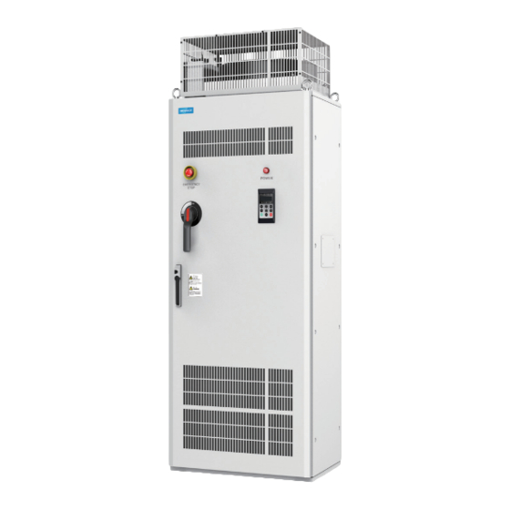
1 Product Information 1.2 Components MD500 T13 models include two structure types: the standard cabinet and the cabinet unit with a distribution cabinet. The following figures show their internal electrical components. Top protective cover Coolant inlet Top cooling fan Hoisting ring Air inlet Emergency stop DC reactor... -
Page 16: Technial Specifications
1 Product Information 1.3 Technial Specifications Table 1-1 Models and technical data Specification Item MD500T500G(-A) MD500T560G(-A) MD500T630G(-A) (kW) Applicable motor (HP) Rated output current(A) 1020 1120 Output voltage 0 to input voltage Outputs Maximum output 500 Hz (editable through a parameter) frequency 0.8 to 8.0 kHz (automatically adjusted according to the Carrier frequency... - Page 17 1 Product Information Table 1-2 Technical specifications of MD500 series AC drives Item Description Input frequency Digital setting: 0.01 Hz resolution Analog setting: Maximum frequency x 0.025% Sensorless vector control (SVC) Control mode Feedback vector control (FVC) Voltage/Frequency (V/F) control 0.25 Hz/150% (SVC)
- Page 18 The optional programming card supports secondary User programmable development in a programming environment function compatible with the Inovance programmable logic controller (PLC). Software in the AC drive allows users to configure Advanced commissioning some operating parameters, and provides a virtual software oscilloscope display that shows system status.
- Page 19 1 Product Information Item Description Allows different methods of switching between running Running command commands: Operating panel; terminal I/O control; and serial communication Supports up to 10 frequency reference setting channels and allows different methods of switching between frequency reference setting channels: Main frequency reference ◆...
- Page 20 1 Product Information Item Description Input phase loss protection Phase loss protection Output phase loss protection Instantaneous The AC drive stops when 250% of the rated output overcurrent protection current is exceeded. The AC drive stops when the DC voltage of the main Overvoltage protection circuit is above 820 V.
-
Page 21: Overall Dimensions
1 Product Information 1.4 Overall Dimensions Output cable Input cable 4-Φ15 73.5 Figure 1-5 Mounting dimensions of MD500T500G to MD500T630G (standard cabinets) (unit: mm) - 20 -... - Page 22 1 Product Information Output cable Input cable 4-Φ15 73.5 1205 Figure 1-6 Mounting dimensions of MD500T500G-A to MD500T630G-A (with auxiliary distribution cabinet) (unit: mm) - 21 -...
-
Page 23: System Connection
2 System Connection 2 System Connection 2.1 System Composition Table 2-1 Description of peripheral electrical devices in the MD500 series AC drive system Device Mounting Location Function Description MCCB: Cuts off power supply when overcurrent occurs on downstream devices. Between the power... -
Page 24: Options
Peripherals and options include braking units and function extension cards, as listed in the following table. For use of each option, see its user manual. If you need to purchase the following options, specify the required option in the order. Table 2-2 Options of MD500 series AC drives Name Model... -
Page 25: Selection Of Fuses, C2 Emc Filters, And Input Reactors
2 System Connection Name Model Description Remarks Differential Differential encoder resolver interface card, Available for all encoder MD38PG1 5 V power supply models interface card For use with a resolver that has an Resolver Available for all MD38PG4 excitation frequency of 10 kHz. The card interface card models has a DB9 interface. -
Page 26: Selection Of External Braking Units
U x U/R = Pb: ■ U refers to the braking voltage at stable system braking. (Its value varies with the system. The default braking voltage of MD500 series is 760 V. You can set F9-08 to change the value.) ■... - Page 27 2 System Connection 125% Braking Torque Min. Braking Unit Applicable (10% ED, Max. 10s) Resistance MD500 Model Motor Remarks of Braking (kW) Model QTY Specification Resistor (Ω) Input MDBU- 24000 W 3.6 Ω voltage 2.5×4 200-B ≤ 440 VAC MD500T560G(-A) Input MDBU- 24000 W 4.6 Ω...
-
Page 28: Installing The External Braking Unit
2 System Connection 2.4.4 Installing the External Braking Unit Step 1: Remove the side cover of the Step 2: Open the cabinet door, and install the AC drive cabinet. connector busbar of the external braking unit. Step 3: Connect the external braking unit. (Determine the number of braking units to be connected as required. -
Page 29: External Operating Panels
MDKE9 is an optional external LCD keypad. It supports copy, download, and modification of all parameters and is easy to use in both Chinese and English. The following figure shows its appearance and keys. (For details, see "4 Panel Operations" in 19010355 MD500 Series AC Drive Advanced User Guide.) Buckle MDKE9... - Page 30 2 System Connection 26.4 MDKE9 Figure 2-3 Mounting dimensions of the MDKE9 external operating panel (unit: mm) - 29 -...
-
Page 31: Mechanical Installation
3 Mechanical Installation 3 Mechanical Installation 3.1 Mechanical Installation Precautions 3.1.1 Transportation 1 Precautions during transportation ■ The cabinet units are heavy and have a high center of gravity. Do not place the cabinet units on the slope more than 5 degrees. ■... -
Page 32: Mechanical Installation Checklist
Check that you have received all the items specified on the delivery note. Notify the shipping company immediately of any missing components or damage. If you have any problem, contact Inovance or the local agent for technical support. If the cabinet units are damaged during transportation, the electrical safety of the cabinet can no longer be ensured. -
Page 33: Installation
3 Mechanical Installation Item Activity Applicable? Completed The minimum ceiling height required (for unhindered air discharge) must be observed. The cooling air supply and exhaust must not be obstructed and must have sufficient space. □ □ Sufficient space must be reserved after cabinet doors are open as safety passageway. - Page 34 3 Mechanical Installation Dust, oil Direct sunlight Strong vibration (over 1 G) High Combustible temperature and material humidity Combustible material (do not place the AC drive Operating temperature: -10°C to +50°C Corrosive, combustible or explosive gases on surface of combustible materials) Figure 3-4 Installation environment requirements 7) The AC drive must be installed in a fireproof cabinet with doors that provide effective electrical and mechanical protection.
- Page 35 3 Mechanical Installation Figure 3-6 Requirements for the installation ground 4 Installation of the Expansion Screw If the cabinet units are installed on the concrete ground, install the expansion screws in the ground corresponding to the fixing holes of the cabinet units. Step 1 Step 2 Step 3...
- Page 36 3 Mechanical Installation ■ Diameter of the drilling hole < Maximum outer diameter of the expansion screw ■ Depth of the drilling hole > Length of the expansion screw ■ Perpendicular to the ground 2) The expansion screw consists of two movable parts: bolt spring shell and stem. Knock the expansion screw into the hole (below the surface) by using a hammer, as shown in Step 2.
-
Page 37: Transporting Before Unpacking
3 Mechanical Installation 3.2.2 Transporting Before Unpacking 1) Transport the packed product by using the pallet under it. 2) The cabinet units can be transported with a fork-lift truck and hoist. The transportation equipment must have the load capacity larger than the weight of one set of cabinet units. -
Page 38: Unpacking
3 Mechanical Installation 3.2.4 Unpacking 1) During unpacking, put the crowbar into the crate as short as possible to prevent damaging the equipment. Pry off the crate with care and protect yourself from being injured by nails. 2) When removing the inner packing materials such as plastic film, do not use a sharp tool to avoid scratching the equipment. -
Page 39: Removing The Pallet
3 Mechanical Installation 3.2.5 Removing the Pallet Before installing cabinet units, loosen the screws for fastening the transportation pallet and cabinet units in the four corners of the cabinet units, and remove the pallet. Figure 3-11 Lifting the cabinet unit off the pallet 3.2.6 Transporting After Unpacking 1) During installation, use the hoist or a similar device to assist operations. - Page 40 3 Mechanical Installation With auxiliary distribution cabinet Standard cabinet Figure 3-12 Transporting cabinet units after unpacking - 39 -...
-
Page 41: Electrical Installation
4 Electrical Installation 4 Electrical Installation 4.1 Electrical Installation Checklist ■ The cabinet units are operated with high voltages. All connection work must be carried out when the cabinet unit is de-energized. ■ Only trained technicians are allowed to operate the cabinet unit. ■... -
Page 42: Routing Suggestions
4 Electrical Installation ■ The distance between the AC drive and the motor must be as short as possible. ■ The motor cables must be separated from other cables. ■ To avoid electromagnetic interference caused by rapid change of the AC drive output voltage, the motor cables and other cables cannot be laid side by side for a long distance. - Page 43 4 Electrical Installation When routing cables of same signal type, lay the equipotential signal cables at the outer layer, and consider the equipotential signal arrangement in the middle. The following figure shows an example. Digital signal cable Pair of analog signal cables Equipotential connection cable Two different pairs of cables Standard cable...
- Page 44 4 Electrical Installation When certain conductors in a multi-conductor cable are not used, connect all the unused (or reserved) conductors to the equipotential connection point. Electronic Electronic device device Reserved wire not connected to equipotential point Equipotential metal plate Equipotential metal plate Figure 4-4 Handling of the remaining conductor in a multi-conductor cable For the low-level sensor signals and relay signals with a common cable, lay the two cables close to each other, preventing too large loop area.
- Page 45 4 Electrical Installation Power or interfering cable Relay cab le Measuring or s ensitive cable Poor EMC effect Allowed Recommended Figure 4-6 Routing of multiple types of cables The unshielded part of the shielded cable must be as short as possible, and the shield braid is connected to the nearest PE end.
-
Page 46: Standard Wiring Diagram
4 Electrical Installation 4.3 Standard Wiring Diagram The following figure shows the standard wiring of MD500 T13 models. For details about the internal electrical wiring diagram, see "Appendix B Electrical Wiring in the Cabinet" Braking resistor Braking unit Fuse Breaker Filter Reactor Reactor... - Page 47 4 Electrical Installation Terminal Name Description Braking resistor connection (+), (-) Connected to the external braking unit terminal U, V, W AC drive output terminal Connected to a three-phase motor Grounding terminal (PE) Grounding connection ■ Wiring of the grounding terminal (PE) Step 1: Fix the grounding cable on the fixing screw rod, as shown in Figure 4-9.
- Page 48 4 Electrical Installation Figure 4-10 Control circuit cable layout of MD500T500G to MD500T630G (example) Table 4-7 Cable selection Input/Output Side Grounding Cable Input Tightening Recommended Recommended MD500 Model Current Screw Torque Cable Recommended Cable Recommended (N•m) Specification Lug Model Specification Lug Model MD500T500G(-A) 838.1 4 x (3 x 120)
-
Page 49: Description Of Control Circuit Terminals
4 Electrical Installation Figure 4-11 Appearance of the wiring terminal 4.5 Description of Control Circuit Terminals AO1 output selection, voltage output by default AI2 input selection, voltage input by default AI2 input impedance selection, 500 Ω by default (250 Ω optional) Pulse Analog input and Power... - Page 50 4 Electrical Installation Table 4-9 Functions of control circuit terminals Terminal Category Terminal Name Description Mark Provides +10 V power supply to an external unit. +10 V power Max. output current: 10 mA +10V-GND supply Generally used to supply an external potentiometer of 1 to 5 kΩ...
- Page 51 4 Electrical Installation Terminal Category Terminal Name Description Mark Normally- T/A-T/B closed (NC) Contact driving capacity: Relay terminal 250 VAC, 3 A, Cos Φ = 0.4 outputs 30 VDC, 1 A Normally-open T/A-T/C (NO) terminal Interface for the 28-core terminal and optional Extension card cards (I/O extension card, PLC card, and various interface...
-
Page 52: Panel Operation
The LED operating panel allows you to set and modify parameters, monitor system status, and start or stop the AC drive. For details, see 19010355 MD500 Series AC Drive Advanced User Guide. An external LED (MD32NKE1) or LCD (MDKE9) operating panel is also available as an option. -
Page 53: Indicators On The Led Operating Panel
5 Panel Operation Name Function Perform a function switchover as defined by the setting of F7-01 Multifunction (MF.K key function selection). MF.K Menu mode Switch over between menu modes as defined by the setting of FP- selection 03 (Selection of individualized parameter display). QUICK 5.3 Indicators on the LED Operating Panel indicates that the light turns on,... -
Page 54: Basic Operations And Trial Run
(Step 4: See "6.4 Motor Auto-tuning" in 19010355 be disconnected from the load. MD500 Series AC Drive Advanced User Guide. ) After completing auto-tuning and confirming that the motor can be safely (Step 5: See "5.12 Viewing Running Status" in started up, press "RUN"... -
Page 55: Display After Power-On
6 Basic Operations and Trial Run Item Description The motor is idle and not connected to the mechanical Load system. 6.3 Display After Power-on The following table lists the display on the operating panel after the AC drive is powered State Display Description... -
Page 56: Motor Control
6 Basic Operations and Trial Run 6.5 Motor Control Parameter Description Scenario It indicates the SVC mode. It is applicable for common high- F0-01 = 0: performance control scenarios in which one AC drive can drive only one motor, for example, machine tool, centrifuge, drawing machine, and injection molding machine. - Page 57 6 Basic Operations and Trial Run Auto-tuning methods are described below. Motor 1 is used to describe motor auto-tuning methods. If you need to perform auto- tuning on motor 2, set F0-24 (Motor parameter group selection) to 1 (Motor parameter group 2).
-
Page 58: Troubleshooting And Solutions
7 Troubleshooting and Solutions 7 Troubleshooting and Solutions 7.1 Faults and Diagnostics Troubleshoot the faults occurred during operating the AC drive as follows. Fault Fault Name Possible Cause Solution Code A grounding fault or Check whether short-circuit occurs on short circuit exists in the motor, motor cable, or contactor. - Page 59 7 Troubleshooting and Solutions Fault Fault Name Possible Cause Solution Code A grounding fault or Check whether short-circuit occurs on short circuit exists in the motor, motor cable, or contactor. the output circuit. The control mode is SVC Set the motor parameters according to or FVC but motor auto- the motor nameplate and perform motor tuning is not performed.
- Page 60 7 Troubleshooting and Solutions Fault Fault Name Possible Cause Solution Code The input voltage is too Adjust the input voltage to normal range. high. An external force drives Cancel the external force or install a the motor during braking resistor. acceleration.
- Page 61 Fault Name Possible Cause Solution Code The bus voltage Pre-charge fluctuates around the Err08 Contact the agent or Inovance. power fault undervoltage threshold continuously. An instantaneous power Enable the power dip ride through failure occurs. function (F9-59 ≠ 0). The AC drive's input voltage is not within the Adjust the voltage to the normal range.
- Page 62 7 Troubleshooting and Solutions Fault Fault Name Possible Cause Solution Code The ambient Lower the ambient temperature. temperature is too high. The ventilation is Clean the ventilation. clogged. Err14 IGBT overheat The fan is damaged. Replace the cooling fan. The thermistor of IGBT Replace the thermistor.
- Page 63 Check whether the input voltage is too grid is abnormal. high or low. Power supply Err25 unit fault The power supply unit Contact the agent or Inovance. is faulty. Accumulative The accumulative Clear the record by parameter Err26 running time running time reached initialization.
- Page 64 7 Troubleshooting and Solutions Fault Fault Name Possible Cause Solution Code Accumulative The accumulative Clear the record by parameter Err29 power-on time power-on time reached initialization. reached the set value. Check whether the load is disconnected The operation current of or ensure that F9-64 (Load loss detection the AC drive is smaller Err30 Load loss...
-
Page 65: Common Symptoms And Diagnostics
Err61 braking resistor is too overload resistance. small. Short-circuit of The braking module is Err62 Contact the agent or Inovance. braking circuit abnormal. Reset the operation. The control unit of the Water cooling Err64 water cooling system is system fault Replace the control unit faulty. - Page 66 The AC drive is damaged. Contact the agent or Inovance. The cooling fan is damaged or The AC drive Replace the damaged fan. does not rotate. display is normal...
- Page 67 The jumper across OP and +24 V Re-confirm the jumper bar becomes loose. across OP and +24 V. The control board is faulty. Contact the agent or Inovance. Replace the encoder and re- The encoder is faulty. confirm cable connection. The motor speed The encoder connection is Replace the PG card.
-
Page 68: Routine Inspection And Maintenance
8 Routine Inspection and Maintenance 8 Routine Inspection and Maintenance 8.1 Routine Inspection Check the following items daily to ensure normal running and prevent damage to the AC drive. Copy this checklist and sign the "Checked" column after each inspection. Inspection Inspection Points Solutions... -
Page 69: Periodic Inspection
8 Routine Inspection and Maintenance 8.2 Periodic Inspection Inspection Inspection Point Solution Checked Item ◆ Check whether the cabinet of the AC drive is powered off. ◆ Use a vacuum cleaner to suck Inspect for wastes, dirt, and dust on up wastes and dust to prevent General the surface of the AC drive. -
Page 70: Replacing Cooling Fans
8 Routine Inspection and Maintenance 8.3.2 Replacing Cooling Fans 1) Possible damage causes: bearing worn and blade aging 2) Judging criteria: whether there is crack on the blade; whether there is abnormal vibration noise upon startup; whether the blade runs abnormally Removing the Top Fan ①... - Page 71 8 Routine Inspection and Maintenance ③ Disconnect the cables connecting the top fan on the ④ Remove the four screws on X1 terminal block. Then, pull out the cables from the top fan. Then, remove the cable trough. Note that only cables connected to the fan from the cabinet.
- Page 72 8 Routine Inspection and Maintenance Removing the AC Drive Fan in the Cabinet ① Open the cabinet door to expose the AC ② Remove baffles A and B of the AC drive in drive, as shown in the following figure. sequence, as shown in the figure.
-
Page 73: Adding And Replacing Cooling Liquid
8 Routine Inspection and Maintenance 8.3.3 Adding and Replacing Cooling Liquid ■ Adding cooling liquid If A66 is displayed on the operating panel of the AC drive, the level of the cooling liquid is lower than the threshold. (The cooling liquid used is 45% ethylene glycol solution with the freezing temperature of -40℃... - Page 74 8 Routine Inspection and Maintenance ■ Replacing cooling liquid Periodic check (once per year) is recommended. If the cooling liquid becomes yellow, discolors, or has many foreign matters, replace the cooling liquid. It is recommended that the cooling liquid be replaced once every five years. Before adding new cooling liquid, exhaust the original cooling liquid.
-
Page 75: Placing The Safety Pipe Of The Waterproof Baffle
8 Routine Inspection and Maintenance 8.3.4 Placing the Safety Pipe of the Waterproof Baffle For the safety of the AC drive, the waterproof baffle is used to prevent component damage caused by drip due to condensation. The procedure for placing the safety pipe of the waterproof baffle is as follows. -
Page 76: Replacing The Dust Filter Foam
8 Routine Inspection and Maintenance 8.3.5 Replacing the Dust Filter Foam When the dust filter foam is dusty and heat dissipation of the cabinet door is affected, clean or replace the dust filter foam by following the procedure below. Removing the Dust Filter Foam ①... -
Page 77: Storage
For storage of the AC drive, pay attention to the following three aspects: 1) Pack the AC drive with the original packing box provided by Inovance. 2) Do not expose the AC drive to moisture, high temperature or outdoor direct sunlight for a long time. -
Page 78: Appendix A Parameter Table
*: The parameter is a factory parameter and can be set only by the manufacturer. ◆ The following tables list only the parameters. For details about their explanation and usage, see 19010355 MD500 Series AC Drive Advanced User Guide. NOTE A.1 Standard Parameter Table... - Page 79 Appendix A Parameter Table Param. Name Setting Range Default Change Tens: main and auxiliary calculation formula 0: Main + auxiliary Final Frequency 1: Main - auxiliary F0-07 reference setting 2: Max. (main, auxiliary) ☆ 3: Min. (main, auxiliary) selection Ones: Frequency reference selection 0: Main frequency reference 1: Main and auxiliary calculation (based on tens position) 2: Switchover between main and auxiliary...
- Page 80 Appendix A Parameter Table Param. Name Setting Range Default Change Frequency offset of auxiliary frequency F0-21 setting channel for 0.00 Hz to F0-10 (Max. frequency) 0.00 Hz ☆ main and auxiliary calculation Frequency reference F0-22 2: 0.01 Hz ★ resolution Retentive of digital F0-23 setting frequency...
- Page 81 Appendix A Parameter Table Param. Name Setting Range Default Change Rated motor Model F1-04 0.01 Hz to max. frequency ★ frequency dependent Model F1-05 Rated motor speed 1 rpm to 65535 rpm ★ dependent Auto- 0.001 Ω to 65.535 Ω (AC drive power ≤ 55 kW) F1-06 Stator resistance tuning ★...
- Page 82 Appendix A Parameter Table Param. Name Setting Range Default Change Vector control slip F2-06 50% to 200% 100% ☆ compensation gain Speed feedback filter F2-07 0.000s to 0.100s 0.015s ☆ time in SVC 0: F2-10 5: Serial comms. 1: AI1 6: Min.
- Page 83 Appendix A Parameter Table Param. Name Setting Range Default Change Cut-off frequency of F3-02 0.00 Hz to the maximum frequency 50.00 Hz ★ torque boost Multi-point V/F F3-03 0.00 Hz to F3-05 (Multi-point V/F frequency 2) 0.00 Hz ★ frequency 1 Multi-point V/F F3-04 0.0% to 100.0%...
- Page 84 Appendix A Parameter Table Param. Name Setting Range Default Change Voltage gain for F3-25 0 to 100 ☆ voltage limit Frequency rise F3-26 threshold during 0 to 50 Hz 5 Hz ★ voltage limit Group F4: Input Terminals F4-00 DI1 function selection 0: No function 30: Pulse input (enabled ★...
- Page 85 Appendix A Parameter Table Param. Name Setting Range Default Change F4-10 DI filter time 0.000s to 1.000s 0.010s ☆ 0: Two-wire control mode 1 Terminal I/O control 1: Two-wire control mode 2 F4-11 ★ mode 2: Three-wire control mode 1 3: Three-wire control mode 2 Terminal UP/DOWN F4-12...
- Page 86 Appendix A Parameter Table Param. Name Setting Range Default Change Hundreds: AI3 curve sele ction, sa me as the ones position F4-33 AI curve selection ☆ Tens: AI2 curve sele ction, sa me as the ones position Ones: AI1 curve sele ction 1: Curve 1 (2 points, se e F4-13 t o F4-16) 2.
- Page 87 Appendix A Parameter Table Param. Name Setting Range Default Change Ten Thousands: DI10 active mode 0: High level active 1: Low level active Thousands: DI9 active DI active mode mode F4-39 0: High level active 00000 ★ 1: Low level active selection 2 Hundreds: DI8 active mode...
- Page 88 Appendix A Parameter Table Param. Name Setting Range Default Change FMR function 0: No output 23: Zero-speed running selection (open 1: AC drive running F5-01 2 (having output at ☆ collector output 2: Fault output (coast to stop) terminal) stop) 24: Accumulative 3: Frequency-level Control board relay...
- Page 89 Appendix A Parameter Table Param. Name Setting Range Default Change FMP function 0: Running frequency F5-06 11: Count value ☆ selection 1: Set frequency 12: Communication 2: Output current AO1 function setting F5-07 ☆ selection 3: Output torque 13: Motor rotational (absolute value, speed proportion to motor...
- Page 90 Appendix A Parameter Table Param. Name Setting Range Default Change Group F6: Start/Stop Control 0: Direct start 1: Catching a spinning motor F6-00 Start mode ☆ 2: Pre-excited start (AC asynchronous drive) 3: SVC quick start 0: From stop frequency Mode of catching a F6-01 1: From power frequency...
- Page 91 Appendix A Parameter Table Param. Name Setting Range Default Change Group F7: Operating Panel and Display LED default display F7-00 0 to 1 ☆ check 0: MF.K key disabled 2: Switchover between 1: Switchover from forward rotation and MF.K key function F7-01 remote control (terminal reverse rotation...
- Page 92 Appendix A Parameter Table Param. Name Setting Range Default Change 0000 to FFFF Frequency reference (Hz) Bus voltage (V) DI state DO state AI1 voltage (V) Display stop AI2 voltage (V) F7-05 ☆ AI3 voltage (V) parameters Count value 10 9 Length value PLC stage Load speed...
- Page 93 Appendix A Parameter Table Param. Name Setting Range Default Change Model F8-04 Deceleration time 2 0.0s to 6500.0s ☆ dependent Model F8-05 Acceleration time 3 0.0s to 6500.0s ☆ dependent Model F8-06 Deceleration time 3 0.0s to 6500.0s ☆ dependent F8-07 Acceleration time 4 0.0s to 6500.0s 0.0s...
- Page 94 Appendix A Parameter Table Param. Name Setting Range Default Change Frequency detection F8-29 0.0% to 100.0% (FDT2 level) 5.0% ☆ hysteresis 2 Detection of F8-30 0.00 Hz to the maximum frequency 50.00 Hz ☆ frequency 1 Detection width of F8-31 0.0% to 100.0% (maximum frequency) 0.0% ☆...
- Page 95 Appendix A Parameter Table Param. Name Setting Range Default Change Running time F8-53 0.0 to 6500.0min 0.0 min ☆ threshold this time Output power F8-54 0.00% to 200.0% 100.0% ☆ correction coefficient Group F9: Fault and Protection Motor overload F9-00 0: Disabled 1: Enabled ☆...
- Page 96 Appendix A Parameter Table Param. Name Setting Range Default Change Output phase loss Tens: Output phase loss protection F9-13 ☆ before running protection 0: Disabled 1: Enabled Ones: Output phase loss protection 0: Disabled 1: Enabled 0: No fault 21: Parameter read and F9-14 1st fault type -...
- Page 97 Appendix A Parameter Table Param. Name Setting Range Default Change DO state upon 3rd F9-21 0 to 9999 ● (latest) fault AC drive state upon F9-22 0 to 65535 ● 3rd (latest) fault Power-on time upon F9-23 0s to 65535s ●...
- Page 98 Appendix A Parameter Table Param. Name Setting Range Default Change Ten Thousands: Communication fault (Err16) Fault protection Thousands: External fault (Err15) F9-47 00000 ☆ action selection 1 Hundreds: Output phase loss (Err13) Tens: Input phase loss (Err12) Ones: Motor overload (Err11) 0: Coast to stop 1: Stop according to the stop mode 2: Continue to run...
- Page 99 Appendix A Parameter Table Param. Name Setting Range Default Change Reserved Fault protection Reserved F9-50 00000 ☆ action selection 4 Hundreds: Initial position fault (Err51) Tens: Motor overspeed (Err43) Ones: Too large speed feedback error (Err42) 0: Coast to stop 1: Stop according to the stop mode 2: Continue to run 0: Current running...
- Page 100 Appendix A Parameter Table Param. Name Setting Range Default Change Detection time of F9-70 0.0s: Not detected 0.1 to 60.0s 5.0s ☆ speed error Power dip ride- F9-71 0 to 100 ☆ through gain Kp Power dip ride- F9-72 through integral 0 to 100 ☆...
- Page 101 Appendix A Parameter Table Param. Name Setting Range Default Change PID error 1 for auto FA-19 0.0% to FA-20 (PID error 2 for auto switchover) 20.0% ☆ switchover PID error 2 for auto FA-20 FA-19 (PID error 1 for auto switchover) to 100.0% 80.0% ☆...
- Page 102 Appendix A Parameter Table Param. Name Setting Range Default Change FC-13 Reference 13 -100.0% to 100.0% 0.0% ☆ FC-14 Reference 14 -100.0% to 100.0% 0.0% ☆ FC-15 Reference 15 -100.0% to 100.0% 0.0% ☆ 0: Stop after running one cycle Simple PLC running FC-16 1: Keep final values after running one cycle...
- Page 103 Appendix A Parameter Table Param. Name Setting Range Default Change Acceleration/ FC-31 Deceleration time of 0 to 3 ☆ simple PLC reference 6 Running time of simple FC-32 0.0s (h) to 6553.5s (h) 0.0s (h) ☆ PLC reference 7 Acceleration/ FC-33 Deceleration time of 0 to 3...
- Page 104 Appendix A Parameter Table Param. Name Setting Range Default Change Time unit of simple PLC FC-50 0: s 1: h ☆ running 0: Set by FC-00 5: PID (Reference 0) 6: Set by preset 1: AI1 frequency (F0-08), FC-51 Reference 0 source ☆...
- Page 105 Appendix A Parameter Table Param. Name Setting Range Default Change Modbus protocol Tens: PROFIBUS-DP selection and 0: PPO1 format FD-05 ☆ PROFIBUS-DP data 1: PPO2 format 2: PPO3 format frame 3: PPO5 format Ones: Modbus 0: Non-standard Modbus protocol 1: Standard Modbus protocol Current 0: 0.01 A (valid when ≤...
- Page 106 Appendix A Parameter Table Param. Name Setting Range Default Change Group FE: User-Defined Parameters User-defined FE-00 U3-17 ☆ parameter 0 User-defined FE-01 U3-18 ☆ parameter 1 User-defined FE-02 F0.00 ☆ parameter 2 User-defined FE-03 F0.00 ☆ parameter 3 User-defined FE-04 F0.00 ☆...
- Page 107 Appendix A Parameter Table Param. Name Setting Range Default Change User-defined FE-23 F0.00 ☆ parameter 23 User-defined FE-24 F0.00 ☆ parameter 24 User-defined FE-25 F0.00 ☆ parameter 25 F0-00 to FP-xx User-defined A0-00 to Ax-xx FE-26 F0.00 ☆ parameter 26 U0-00 to U0-xx U3-00 to U3-xx User-defined...
- Page 108 Appendix A Parameter Table Param. Name Setting Range Default Change Group A0: Torque Control and Limit Speed/Torque control A0-00 0: Speed control 1: Torque control ★ selection 5: Communication 0: Set by A0-03 reference Torque reference 1: AI1 6: Min. (AI1, AI2) A0-01 source in torque 2: AI2...
- Page 109 Appendix A Parameter Table Param. Name Setting Range Default Change Ten thousands: VDI5 0: Disabled 1: Enabled Selection of VDI active Thousands: VDI4 A1-06 00000 ★ 0: Disabled state 1: Enabled Hundreds: VDI3 0: Disabled 1: Enabled Tens: VDI2 0: Disabled 1: Enabled Ones: VDI1 0: Disabled...
- Page 110 Appendix A Parameter Table Param. Name Setting Range Default Change A1-16 VDO1 output delay 0.0s to 3600.0s 0.0s ☆ A1-17 VDO2 output delay 0.0s to 3600.0s 0.0s ☆ A1-18 VDO3 output delay 0.0s to 3600.0s 0.0s ☆ A1-19 VDO4 output delay 0.0s to 3600.0s 0.0s ☆...
- Page 111 Appendix A Parameter Table Param. Name Setting Range Default Change 0: ABZ incremental A2-28 Encoder type 2: Resolver ★ encoder Speed feedback 0: Local PG card A2-29 2: Pulse input (DI5) ★ channel selection 1: Extension PG card A/B phase sequence A2-30 of ABZ incremental 0: Forward...
- Page 112 Appendix A Parameter Table Param. Name Setting Range Default Change 0: Set by F2-10 (Digital 6: Min. (AI1, AI2) setting of torque limit in 7: Max. (AI1, AI2) speed control) 8: Set by F2-12 [Digital Torque limit source 1: AI1 setting of torque A2-49 in speed control...
- Page 113 Appendix A Parameter Table Param. Name Setting Range Default Change PWM modulation 0: Asynchronous 1: Synchronous A5-01 ☆ pattern modulation modulation Dead zone 1: Enabled A5-02 compensation mode 0: Disabled (compensation mode ☆ selection 0: Random PWM invalid A5-03 Random PWM depth ☆...
- Page 114 Appendix A Parameter Table Param. Name Setting Range Default Change AI curve 5 inflection 2 A6-10 (AI curve 5 inflection 1 input) to A6-14 (AI A6-12 3.00 V ☆ input curve 5 max. input) Corresponding A6-13 percentage of AI curve -100.0% to +100.0% 30.0% ☆...
- Page 115 Appendix A Parameter Table Param. Name Setting Range Default Change A7-03 FMP output 0.0% to 100.0% 0.0% ☆ A7-04 AO1 output 0.0% to 100.0% 0.0% ☆ Hundreds: DO Selection of PLC 0: Disabled 1: Enabled A7-05 program controlling ☆ digital output Tens: Relay 1 0: Disabled 1: Enabled...
- Page 116 Appendix A Parameter Table Param. Name Setting Range Default Change Gain of received data A8-05 -10.00 to 100.00 1.00 ★ (torque) Point-to-point communication A8-06 0.0 to 10.0s 1.0s ☆ interruption detection time Master data sending A8-07 cycle in point-to-point 0.001s to 10.000s 0.001s ☆...
-
Page 117: Monitoring Parameters
Appendix A Parameter Table Param. Name Setting Range Default Change AO2 measured Factory- AC-19 -10.00 V to 10.000 V ☆ voltage 2 corrected A.2 Monitoring Parameters Communication Param. Name Minimum Unit Address Group U0: Monitoring Parameters U0-00 Running frequency 0.01 Hz 7000H U0-01 Frequency reference... - Page 118 Appendix A Parameter Table Communication Param. Name Minimum Unit Address Target voltage upon V/F U0-39 7027H separation Output voltage upon V/F U0-40 7028H separation U0-41 DI state display 7029H U0-42 DO state display 702AH DI set for function state U0-43 702BH display 1 (function 01-40) DI set for function state...
-
Page 119: Appendix B Electrical Wiring In The Cabinet
Appendix B Electrical Wiring in the Cabinet Appendix B Electrical Wiring in the Cabinet The following figure shows the electrical wiring in the cabinet. 1600A RU2:U FAN1:U F1-F3 M1:U IO:DI6 ES:11 Optional F1 RU2:V FAN1:V IO:DI8 Liquid level M1:V ES:12 KA1:9 FAN1:W RU2:W... -
Page 120: Warranty Agreement
Warranty Agreement Warranty Agreement 1) Inovance provides an 18-month free warranty to the equipment itself from the date of manufacturing for the failure or damage under normal use conditions. 2) Within the warranty period, maintenance will be charged for the damage caused by the following reasons: a. - Page 121 Service Hotline: 400-777-1260 http: //www.inovance.com Suzhou Inovance Technology Co., Ltd. Add.: No. 16 Youxiang Road, Yuexi Town, Wuzhong District, Suzhou 215104, P.R. China Tel: +86-512-6637 6666 Fax: +86-512-6285 6720 Service Hotline: 400-777-1260 http: //www.inovance.com Copyright Shenzhen Inovance Technology Co., Ltd.
Need help?
Do you have a question about the MD500 Series and is the answer not in the manual?
Questions and answers