Advertisement
Quick Links
DESCRIPTIO
This demonstration circuit is an N-channel half-bridge for
general purpose applications. The half-bridge can be driven
with TTL/CMOS level signals into an LT
drives the N-channel MOSFETs. A self-contained high-
side driver regulator allows PWM operation to 100% duty
cycle without discontinuities. By adding a controller IC and
PERFORMANCE
SYMBOL
PARAMETER
V
LT1336 Input Voltage Range
IN
I
LT1336 Typical Supply Current
Q
HV
High Voltage Range
R
Power MOSFETs R
DS(ON)
ESR
ESR of Bypass Capacitor
I
Max Ripple Current
PK
P
Max Power Input
IN
f
Max Operating Frequency
MAX
Note 1: For applications requiring higher input power, attach heat sinks to all power MOSFETs.
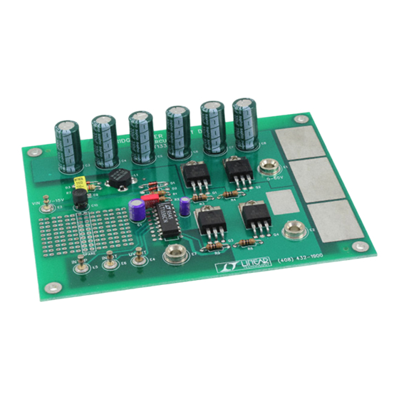
BOARD PHOTOS
Demo Board with a Flyback High-Side Driver Regulator
®
1336, which
SUMM
ARY
Operating Temperature Range 0°C to 50°C, V
DS(ON)
DEMO MANUAL DC102
50V N-CHANNEL HALF BRIDGE
LT1336 Half-Bridge N-Channel
Power MOSFET Driver
with Boost/Flyback Regulator
some other components in the space provided for
prototyping, this demo board can be turned into a com-
plete system solution. The half-bridge consists of four
power MOSFETs, two paralleled topside MOSFETs and
two paralleled bottom side MOSFETs.
, LTC and LT are registered trademarks of Linear Technology Corporation.
CONDITION
INTOP = INBOTTOM = 0V
V
= 10V
GS
100kHz
(Note 1)
Demo Board with a Boost High-Side Driver Regulator
= 12V unless otherwise noted.
IN
10V to 15V
0V to 50V (60V Abs Max)
VALUE
15mA
0.09Ω
0.03Ω
4.5A
150W
100kHz
1
Advertisement

Related Manuals for Linear Technology DC102


Summary of Contents for Linear Technology DC102
- Page 1 MOSFETs. side driver regulator allows PWM operation to 100% duty cycle without discontinuities. By adding a controller IC and , LTC and LT are registered trademarks of Linear Technology Corporation. PERFORMANCE SUMM Operating Temperature Range 0°C to 50°C, V = 12V unless otherwise noted.
- Page 2 DEMO MANUAL DC102 50V N-CHANNEL HALF BRIDGE PACKAGE AND SCHEMATIC DIAGRAMS TOP VIEW SENSE 1N4148 SWGND R2,2Ω 10V TO 15V BOOST INTOP 1/4W, 5% TGATEDR INBOTTOM TGATEFB UVOUT 1N4148 6.2k 10µF 1/4W TSOURCE SGND 1000pF 1/4W 0.1µF PGND 1N4148 BGATEDR...
-
Page 3: Operation
DEMO MANUAL DC102 50V N-CHANNEL HALF BRIDGE PA S LIST REFERENCE DESIGNATOR QUANTITY PART NUMBER DESCRIPTION VENDOR TELEPHONE 25SC10M 10µF 25V 20% Electrolytic Capacitor Sanyo (619) 661-6835 25SC1M 1µF 25V 20% Electrolytic Capacitor Sanyo (619) 661-6835 C3 to C8 63MV330CZ 330µF 63V Aluminum Capacitor... - Page 4 DEMO MANUAL DC102 50V N-CHANNEL HALF BRIDGE OPERATION generator to INTOP (E5) and INBOTTOM (E6). These mum operating frequency. The regulator voltage across inputs to the LT1336 are TTL/CMOS compatible and can – V is 10.6V. Unlike bootstrapping tech- BOOST...
- Page 5 DEMO MANUAL DC102 50V N-CHANNEL HALF BRIDGE OPERATION floating capacitor. Thus, at a point between 90% and tions where the high voltage rail does not exceed 40V, the 100% duty cycles, the floating capacitor will be depleted, boost topology can be used. The advantage, as shown in causing a discontinuity and potential overdissipation of Figure 2, is simplicity .
- Page 6 DEMO MANUAL DC102 50V N-CHANNEL HALF BRIDGE PC LAYOUT AND FILM Component Side Silkscreen Component Side Component Side Pastemask Component Side Solder Mask...
- Page 7 Information furnished by Linear Technology Corporation is believed to be accurate and reliable. However, no responsibility is assumed for its use. Linear Technology Corporation makes no represen- tation that the interconnection of its circuits as described herein will not infringe on existing patent rights.
- Page 8 5. ALL DIMENSIONS ARE IN INCHES 0.205 0.156 0.072 TOTAL HOLES LT/GP 0197 500 • PRINTED IN USA Linear Technology Corporation 1630 McCarthy Blvd., Milpitas, CA 95035-7417 (408) 432-1900 FAX: (408) 434-0507 TELEX: 499-3977 www.linear-tech.com © LINEAR TECHNOLOGY CORPORATION 1997...
- Page 9 X-ON Electronics Largest Supplier of Electrical and Electronic Components Click to view similar products for category: Power Management IC Development Tools Click to view products by manufacturer: Analog Devices Other Similar products are found below : EVAL-ADM1168LQEBZ EVB-EP5348UI MIC23451-AAAYFL EV MIC5281YMME EV DA9063-EVAL ADP122-3.3-EVALZ ADP130- 0.8-EVALZ ADP130-1.2-EVALZ ADP130-1.5-EVALZ ADP130-1.8-EVALZ ADP1714-3.3-EVALZ ADP1716-2.5-EVALZ ADP1740-1.5- EVALZ ADP1752-1.5-EVALZ ADP1828LC-EVALZ ADP1870-0.3-EVALZ ADP1871-0.6-EVALZ ADP1873-0.6-EVALZ ADP1874-0.3- EVALZ ADP1882-1.0-EVALZ ADP199CB-EVALZ ADP2102-1.25-EVALZ ADP2102-1.875EVALZ ADP2102-1.8-EVALZ ADP2102-2-...
Need help?
Do you have a question about the DC102 and is the answer not in the manual?
Questions and answers