Advertisement
Description
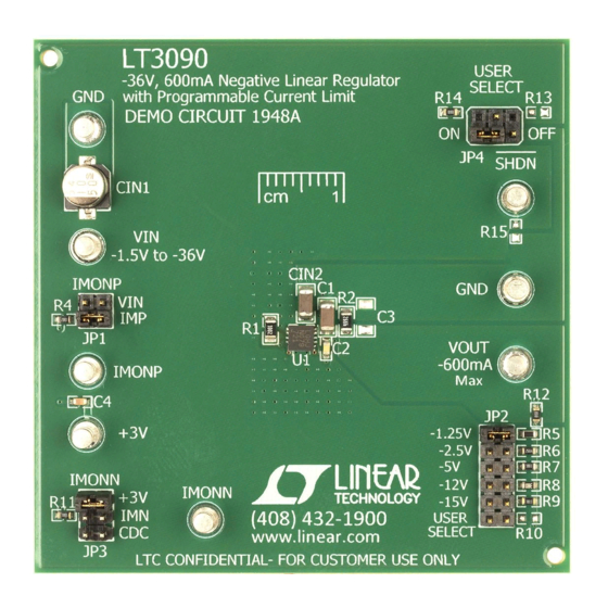
Demonstration circuit 1948A is a 600mA low dropout
negative linear regulator featuring the
is designed for applications requiring negative output volt-
age, high current with no heat sink, output adjustability to
zero and low dropout voltage.
The LT3090 features fast transient response, high PSRR
and low output noise. The LT3090 supplies 600mA at a
typical dropout voltage of 300mV. Operating quiescent cur-
rent is nominally 1mA and drops to << 1μA in shutdown.
A single resistor adjusts the LT3090's precision program-
mable current limit. The LT3090's positive or negative
current monitor either sources a current (0.5mA/A) or
performance summary
SYMBOL
PARAMETER
V
Input Supply Range
IN
V
Output Voltage
OUT
I
Output Current
OUT
Note 1. This is for the typical condition when V
for details.
Arrow.com.
Downloaded from
–36V, 600mA Negative Linear Regulator
with Programmable Current Limit
sinks a current (1mA/A) proportional to output current.
LT
3090. This device
Built-in protection includes reverse output protection,
®
internal current limit with foldback and thermal shutdown
with hysteresis.
The LT3090 is offered in a 10 pin DFN package and a
16-lead MSOP package.
The LT3090 data sheet gives a complete description of
the device, operation and application information. The data
sheet should be read in conjunction with this quick start
guide for working on or modifying the demo circuit 1948A.
Design files for this circuit board are available at
http://www.linear.com/demo/DC1948A
L, LT, LTC, LTM, Linear Technology and the Linear logo are registered trademarks of Linear
Technology Corporation. All other trademarks are the property of their respective owners.
Specifications are at T
CONDITIONS
V
= 1.2V, I
= 1mA
OUT
OUT1
Shunt at 1, 2 for JP1
Shunt at 3, 4 for JP1
Shunt at 5, 6 for JP1
Shunt at 7, 8 for JP1
Shunt at 9, 10 for JP1
Shunt at 11, 12 for JP1 and R10 Stuffed as 357kΩ
R1 = 10k, (Note 1)
– V
< 5V. Current limit varies with different values of V
IN
OUT
DEMO MANUAL DC1948A
= 25°C
A
MIN
–36
–1.286
–2.575
–5.15
–12.36
–15.45
–18.54
600
– V
. Refer to the LT3090 data sheet
IN
OUT
LT3090
TYP
MAX
UNITS
–1.5
V
–1.25
–1.213
V
–2.5
–2.425
V
–5
–4.85
V
–12
–11.64
V
–15
–14.55
V
–18
–17.46
V
mA
dc1948af
1
Advertisement
Table of Contents

Related Manuals for Linear Technology DC1948A


Summary of Contents for Linear Technology DC1948A
- Page 1 Design files for this circuit board are available at current monitor either sources a current (0.5mA/A) or http://www.linear.com/demo/DC1948A L, LT, LTC, LTM, Linear Technology and the Linear logo are registered trademarks of Linear Technology Corporation. All other trademarks are the property of their respective owners. performance summary Specifications are at T = 25°C...
- Page 2 NOTE. Make sure that the power dissipation is limited 3. With power off, connect the input power supply to VIN below the thermal limit. and GND. Figure 1. DC1948A Proper Equipment Setup Figure 2. Measuring Input or Output Ripple dc1948af Arrow.com.
- Page 3 DEMO MANUAL DC1948A positive or negative current monitor configuration There are both positive and negative current monitors on When the negative current monitor is in use, JP1 needs the LT3090. The configurations for these two monitors are to be configured on VIN position and JP3 needs to be different.
- Page 4 DEMO MANUAL DC1948A parts list ITEM QTY REFERENCE PART DESCRIPTION MANUFACTURER/PART NUMBER Required Circuit Components C1, CIN2 CAP, X7R 4.7µF 50V 10% 1206 TDK C3216X7R1H475KT CAP, X7R 0.1µF 16V 10% 0603 AVX 0603YC104KAT2A CAP, X7R 1µF 10V 10% 0603 TAIYO YUDEN LMK107BJ105KA RES, CHIP 10k 0.1W 1% 0805...
- Page 5 Information furnished by Linear Technology Corporation is believed to be accurate and reliable. However, no responsibility is assumed for its use. Linear Technology Corporation makes no representa- tion that the interconnection of its circuits as described herein will not infringe on existing patent rights.
- Page 6 Linear Technology Corporation (LTC) provides the enclosed product(s) under the following AS IS conditions: This demonstration board (DEMO BOARD) kit being sold or provided by Linear Technology is intended for use for ENGINEERING DEVELOPMENT OR EVALUATION PURPOSES ONLY and is not provided by LTC for commercial use. As such, the DEMO BOARD herein may not be complete in terms of required design-, marketing-, and/or manufacturing-related protective considerations, including but not limited to product safety measures typically found in finished commercial goods.
Need help?
Do you have a question about the DC1948A and is the answer not in the manual?
Questions and answers