Table of Contents
Advertisement
Quick Links
Advertisement
Table of Contents

Related Manuals for Maxtang EHL-10


Summary of Contents for Maxtang EHL-10
- Page 1 EHL-10 Mini-ITX Motherboard...
- Page 2 Copyright © 2021 Shenzhen Maxtang Computer Co., Ltd. All rights reserved. No part of this publication may be reproduced, copied, stored in a retrieval system, translated into any language, or transmitted in any form or by any means, electronic, mechanical, photocopying, or otherwise, without the prior written consent of Shenzhen Maxtang Computer Co., Ltd (hereinafter referred to as “Maxtang”).
-
Page 3: Ehl10 Motherboard
Shenzhen Maxtang Computer Co., Ltd EHL-10 Motherboard User Manual (Version 0.5) Version: Description Issue Date: V0.5 Initial Version 2021/08/13... -
Page 4: Table Of Contents
Shenzhen Maxtang Computer Co., Ltd Contents EHL10 Motherboard ................1 User Manual ..................1 (Version 0.5) ..................1 Chapter 1 Product Introduction ......................3 1.1 Brief Introduction ......................3 1.2 Parameters ........................3 1.3 Connector Diagram ......................4 Chapter 2 Hardware ................6 2.1 Jumper Setting ........................6 2.2 Memory Slots ........................6... -
Page 5: Chapter 1 Product Introduction
Shenzhen Maxtang Computer Co., Ltd Chapter 1 Product Introduction 1.1 Brief Introduction The EHL-10 is a mini ITX motherboard based on the Intel Elkhart Lake platform; features a small form factor, low power consumption, and high performance. 1.2 Parameters CPU: Intel Atom x6425RE——4Cores 4Threads, Base Frequency 1.9GHz, TDP 12W... -
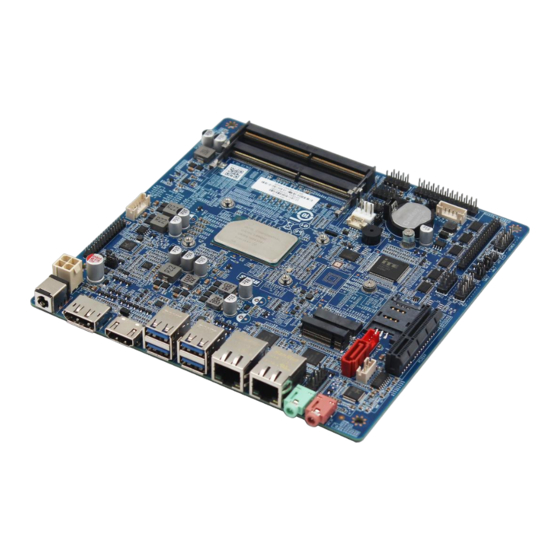
Page 6: Connector Diagram
Shenzhen Maxtang Computer Co., Ltd 1.3 Connector Diagram HDMI 2*USB3.2 2*USB3.2 LAN2 LAN1 LINE_OUT MIC_IN DC_IN FP-AUDIO PWR2 SATA JAUD M.2_S L_VCC/BKL LVDS/EDP PWSATA M.2_E PCIEX4 COM2 L_BKL COM1 CPU_FAN SYS_FAN GPIO SO-DIMM JPOWER COM36 PS2_H 2*USB2.0 2*USB2.0... - Page 7 Shenzhen Maxtang Computer Co., Ltd...
-
Page 8: Chapter 2 Hardware
Shenzhen Maxtang Computer Co., Ltd Chapter 2 Hardware 2.1 Jumper Setting Please configure the jumpers according to your requirements before installing the hardware. How to identify the first header of jumpers and pins: Observe the mark beside the jumper or pins and find the header marked by “1”... - Page 9 Shenzhen Maxtang Computer Co., Ltd LCD_BKL_ADJ LCD_BKL_ON LVDS working Voltage and two-way adjustment jumper (Screen Printing: L_VCC/BKL) Setting Function Close VCC 3.3V Close VCC 5V Close REV (Backlight Control Reverse) 55-6 Close STD (Backlight Control Standard) 2.3.2 eDP (Optional) Optional function, the board supports 2LANE eDP1.3 interface. When it is set as eDP functions, the pin transmits the eDP signal and disables the LVDS function.
-
Page 10: Storage
Shenzhen Maxtang Computer Co., Ltd LCD_BKL_ON EDP working voltage and two-way adjustment jumper (Screen printing: L_VCC/BKL) Interface Setting Functions Close VCC 3.3V Close VCC 5V Close REV (Backlight control reverse) Close STD (Backlight control standard) 2.4 Storage The board features 1x SATA3.0 standard interface, transmission rate at 6GB/s, a disk power supply socket;... - Page 11 Shenzhen Maxtang Computer Co., Ltd Signal Signal DCD# DTR# DSR# RTS# CTS# (NC) COM36 pin definition (Screen: COM36) Signal Signal DCD# DTR# DSR# RTS# CTS# (NC) DCD# DTR# DSR# RTS# CTS# (NC) DCD# DTR# DSR# RTS# CTS# (NC) DCD# DTR#...
-
Page 12: Lpt
Shenzhen Maxtang Computer Co., Ltd DSR# (NC) RTS# (NC) CTS# (NC) (NC) 2.9 LPT A set of 2x13 Pin LPT interfaces onboard. Use an adapter to convert the LPT interface to a standard parallel port for use. Users can connect it to a printer or other devices according to their needs. -
Page 13: Switch Panel Pin
Shenzhen Maxtang Computer Co., Ltd PWR3: ATX12V supplementary power supply socket (2x2PIN) 2.12 Switch Panel Pin The front control panel interfaces are to connect the functional buttons and indicators on the front panel. JPOWER (Screen Printing: JPOWER) Signal Signal HDD_LED+... -
Page 14: Cpu Fan Socket
Shenzhen Maxtang Computer Co., Ltd the latter is set to “Power On”, the device will start automatically after being connected to power. 2.15 CPU FAN Socket The board provides a CPU Fan socket for cooling. 5V default power supply. CPU_FAN (Screen Printing: CPU_FAN) Signal 2.16 System Fan...
Need help?
Do you have a question about the EHL-10 and is the answer not in the manual?
Questions and answers