Table of Contents
Advertisement
Quick Links
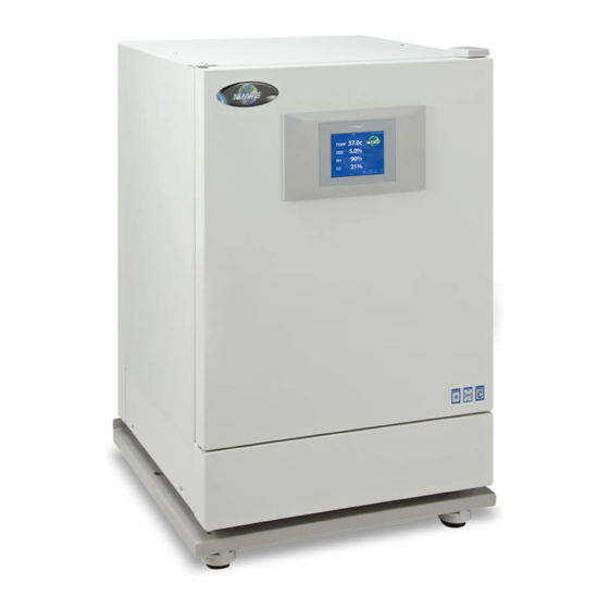
Water-Jacketed Automatic CO
NU-8600, NU-8600E
NU-8625, NU-8625E
NU-8631, NU-8631E
NU-8645, NU-8645E
Operation and Maintenance Manual
September 2022
2100 Fernbrook Lane
Plymouth, MN 55447
Toll-Free: 1-800-328-3352
In Minnesota: (763)-553-1270
Fax: (763)-553-0459
Models
Revision 9
Series 3
Manufactured By:
NuAire, Inc.
Incubator
2
Advertisement
Table of Contents

Subscribe to Our Youtube Channel
Related Manuals for NuAire NU-8625


Summary of Contents for NuAire NU-8625
- Page 1 Water-Jacketed Automatic CO Incubator Models NU-8600, NU-8600E NU-8625, NU-8625E NU-8631, NU-8631E NU-8645, NU-8645E Operation and Maintenance Manual September 2022 Revision 9 Series 3 Manufactured By: NuAire, Inc. 2100 Fernbrook Lane Plymouth, MN 55447 Toll-Free: 1-800-328-3352 In Minnesota: (763)-553-1270 Fax: (763)-553-0459...
-
Page 2: Table Of Contents
Water-Jacketed Water Jacket In-VitroCell CO Incubator Operation & Maintenance Manual NU-8600, NU-8600E NU-8625, NU-8625E NU-8631, NU-8631E NU-8645, NU-8645E Table of Contents Section No. 1 ..........General Description Section No. 2 ..........Performance Parameters and Features Section No. 3 ..........Models & Features Section No. 4 ..........Test Performance & Procedures Section No. -
Page 3: Sterility
Sterility Reliability Like all NuAire equipment, this Incubator has been designed to provide the highest quality standards of performance with matching computer technology, precise temperature control, and CO gas control system combining state-of-the-art technology with years of design, quality, and manufacturing experience. - Page 4 CO, H and various acidic gases such as CO , etc. RH Display (NU-8625 and NU-8645) These Incubators display RH. The system does not control RH, it is just a monitor. 1.8 Safety Instructions These safety instructions describe the safety features of the In-VitroCell Incubator.
- Page 5 1.9 Explanation of symbols Symbol (in text box) Description (in text box) Safety alert symbol indicates a potentially hazardous WARNING situation which, if not avoided, could result in death of serious injury. Safety alert symbol indicates a potentially hazardous CAUTION situation which, if not avoided, may result in minor or moderate injury.
- Page 6 2.0 Performance Parameters and Features • Each chamber’s water-jacket holds 18 to 20 gallons (up to 75.7 liters) of water that, in conjunction with the microcomputer control system, provides an interior chamber temperature uniformity of 0.2C at 37.0C. • The microcomputer temperature control system has two temperature sensors located inside the chamber at the back wall.
- Page 7 3.0 Models & Features 3.1 Dimensions (see also Specification Drawing BCD-18002) Overall Dimensions - inches (mm): All Models Height: Exterior: 37.750 inches (958 mm) Width: 25.625 inches (680 mm) Depth: 27 inches (685 mm) Footprint: 22 inches (557 mm) wide x 17.5 inches (445 mm) deep Height: Interior: 24 inches (611mm) Width:...
- Page 8 analog output signals for system performance. Notes: Performance ratings apply ONLY when the Incubator is installed and set up properly per the instructions in the manual, has stabilized at all set points and is in a stable environment. See sections 8 and 9 for proper set up.
- Page 9 OM0253 Page 9 of 52 Rev 9 September/2022...
- Page 10 4.0 Test Performance & Procedures All equipment is thoroughly inspected at the NuAire Factory at the time of shipment. Quality control is maintained by constant surveillance over the product, beginning at the receipt of purchased material and concluding with a final inspection, which certifies the Incubator performance to the specifications.
- Page 11 However, damage can occur in any shipment and the following paragraph outlines those steps you should take on receipt of a NuAire Incubator to be sure that if damage has occurred, the proper claims and actions are taken immediately.
- Page 12 7.3 Interior Chamber, Shelf & Water Pan Preparation Shelves Incubator is shipped with the shelves installed. The shelf-mounted water pan is also in place that option is ordered NuAire recommends decontamination of all surfaces within the interior chamber, glass door, and outer door with gasket. They can be wiped down with a disinfectant of 70 percent alcohol or a similar non-corrosive antimicrobial agent.
- Page 13 OM0253 Page 13 of 52 Rev 9 September/2022...
- Page 14 7.4 Electrical The electrical supply circuit to the Incubator must conform to all national and local electrical codes. Consult the serial-data plate, located at the front of the right side of the Incubator, for voltage, cycle, phase, and ampere requirements before making a connection. Plug the power cord securely into a grounded power source. VOLTAGE SHOULD NOT VARY MORE THAN 10% FROM SERIAL PLATE RATINGS.
- Page 15 7.7 Air Inlet Connection The air inlet and filter are installed at the Factory. The filter has flexible hose that attaches to bulkhead fittings in the bottom of the front panel and can be found under the valance that is beneath the door. One 50mm polypropylene .3- micron HEPA filter is connected to the hoses.
- Page 16 Incubator. • Some single stage CO pressure regulators have two gauges. USE A TWO-STAGE REGULATOR. All NuAire Incubators use CO in such quantities that precise metering of CO input pressure is important for maximum performance. To connect the regulator: 1.
- Page 17 7.9 Removing the cable ties used to secure the Air pump for shipping: 7.10 Setting up the access port: When utilizing the access port do not block or restrict the relief holes in the center of the port plug. Blocking this venting can cause performance issues for the incubator.
-
Page 18: Humidity
Use mild detergent to clean the exterior of the Incubator. NOTE: NuAire does not offer any product warranty with respect to cleaning material compatibility. USE AT YOUR OWN RISK! The information provided above is from raw material suppliers and known general source documents for use to develop application cleaning SOP’s. -
Page 19: Control System Introduction
8.3 Control System Introduction The NuAire Incubator Control Electronics system is designed to serve the control requirements of the Incubator chamber. Temperature, CO levels in all models and O in available models are controlled by preset values to provide the optimum conditions for culture growth within a chamber. - Page 20 NuTouch LCD menu system is accomplished through the following methods: • Touching a “graphic” Icon like the NuAire Logo in the Main Screen to access the System Settings menu. This is preceded by an Enter Password screen when a password has been established.
- Page 21 Service Settings: Protected by the password 9876, it facilitates Calibrations, Option settings, and access to Diagnostics. System Information: Views the units Model Number, Serial Number, Control board assembly (CCBA) Software Revision and the Display board assembly (LCBA) Software Revision. Display Settings: Brightness: Allows adjustment of the screen brightness.
-
Page 22: Nutouch Display Screen
8.3.9 Diagnostic and calibration assists. To access the Service Settings Menu, perform the following steps: NuAire Logo → Service Settings → 9876 Enter. You are now in the Service Settings Menu (screen). This screen provides you the capability to review and analyze numerous Incubator functions including the following: •... -
Page 23: Rear Component Panel
8.4.6 USB status The USB status icon appears in the lower right side of the Main screen when a memory stick is placed in the USB port to the right of the NuTouch display while downloading performance and event history. This icon disappears when the memory stick is removed from the port. - Page 24 8.5.7 Air Inlet (All Models) This is a free air supply. DO NOT CONNECT TO A PRESSURIZED SOURCE. Air filter is installed at the factory on the front of the unit. 8.6 Front Component Panel The front component panel contains the following functions. See BCD-18476 8.6.1 N Supply filter (Available on NU-8631) The N...
- Page 25 OM0253 Page 25 of 52 Rev 9 September/2022...
- Page 26 OM0253 Page 26 of 52 Rev 9 September/2022...
-
Page 27: Run Mode Operator Interactions
(see Section 11.0). 8.8 Standby Mode Operator Interactions The NuAire incubator automatically enters the standby mode when necessary. There is no action required by the user to enter this mode. - Page 28 8.9.1 Diagnostic Mode To initiate the diagnostic mode, perform the following from the ‘Main’ screen: • Select the NuAire Logo to enter “System Settings” • Select “Service Settings” and enter 9876, and then hit enter (ENT) • In the Service Settings menu, select the “Diagnostics” button for the desired function...
- Page 29 Output/Input Diagnostic Parameter Functions Temperature 1. Safety Relay (on/off) 2. Chamber Temp. Sensor (shows current temp.) 3. Safety Temp. Sensor (shows current temp.) 4. Chamber heater Triac control (0 - 50% - 100 % phase firing) 5. Door Heater Triac control (0 - 50% - 100 % phase firing) 1.
- Page 30 Control Diagnostics 1. CO Sensor This function shows the current CO sensor reading both the “Un-Calibrated sensor signal and the Calibrated value shown in the display screen. 2. CO Inject Valve / on/off This function shows on LCD the current state of the CO inject valve.
- Page 31 Option Configuration Parameters Format: Option (Default, Minimum/Maximum) All the options for the NU-8600 & NU-8631 Incubator use this same format. The default is set at the factory and can be restored in the field with a Master, or a Factory reset command. On the following pages, there is a short description of each Option with its Default/Minimum/Maximum setting, followed by a more detailed description.
- Page 32 5. Recovery Delay Time This value determines the time, in seconds, to turn off the chamber heaters in half-degree increments during a temperature recovery cycle. The delay time is required to prevent temperature overshoot of the control set point. 1. CO₂ System Enable (Enabled/disabled) is located in the bottom right of the screen This function will enable or disable the CO₂...
-
Page 33: Resetting The Electronic Software
Screen Lock button (default Main Screen Unlocked). Pressing this button will change it to “Main screen Locked” (Lockout = 1). This puts a “Press to unlock” button on the NuAire Logo in the Main screen. This feature stops accidental screen changes by brushing the touch screen. You must press and hold (2 seconds) until the message disappears which unlocks the main screen so that you can navigate into;... - Page 34 Setting the model number sets the following function: • All NuAire customers will press NuAire in the “Choose Company” Screen. This will bring up the NuAire logo in the main screen. •...
-
Page 35: Chamber Temperature Calibration
→ → → → • Touch the Serial Number text then enter the 12 digits serial number which can be found on the serial number label located behind the valance under the sample port. Press the ENT button on the keypad screen and you will return to the Factory Set-Up screen showing the serial number you just entered. - Page 36 also be used. No matter what instrument is used the measurement for this calibration should be taken in the middle of the incubator chamber and in a stabilized condition. When the unit has stabilized at the operating temperature, perform the following calibration procedure. •...
-
Page 37: Setting Air Injections
The following steps should be taken for setting these duty cycle percentages: • Allow Incubator to stabilize at its given temperature and humidity level in run mode. • Enter the “Environmental Set Points” screen either from the MAIN SCREEN or the SYSTEM SETTINGS screen. •... - Page 38 SUCH MATERIAL IS HARMFUL TO THE POLISHED STAINLESS STEEL. NOTE: NuAire does not offer any product warranty with respect to cleaning material compatibility. USE AT YOUR OWN RISK! The information provided above is from raw material suppliers and known general source documents for use to develop application cleaning SOP’s.
-
Page 39: Chemical Decontamination
10.1 Chemical Decontamination of the Incubator Chamber To chemically decontaminate NuAire Incubator inner chambers, users may use the traditional formaldehyde or Chlorine Dioxide in gas form, or Vapor Phased Hydrogen Peroxide. All three of the chemicals are compatible to all parts within NuAire Incubator chambers. - Page 40 Responding to the notification: From the main screen press the NuAire Logo / Service settings / General Option / Next/ / Filter Maintenance to access the Filter Maintenance screen. In these screens you can: • Extend the alarm by 1 month by pushing Last Replacement Date, date displays, extend the date by one month.
- Page 41 11.0 Error Indicators & Troubleshooting Step 1 NOTE ALL ERROR INDICATORS When the Incubator is running, the Alarm Status button indicates an error. Pressing the Alarm Status button, entering the correlating Alarms Menu and pressing the Silence button in the Alarms Menu will silence the audible alarm until Diagnostics is entered or another alarm becomes active.
- Page 42 − Faulty TRIAC, replace control board. Temp Under Set Point during normal running and in − Faulty chamber heater contact NuAire Technical Service. − Door heater needs to be increased with a high temperature set-point in a low ambient temperature.
- Page 43 Stops trying to write to USB memory Universal Serial Bus Error tries stick after several tries USB port not functioning contact NuAire technical service − Increase door heater duty cycles. - Glass door, gasket or front wall of − See section 9 for detailed instructions.
- Page 44 − Than 1 Mega Ohm per instructions in manual. Message says Water Supply Low − Float switch bad. Replace. For further assistance, call NuAire Customer Service at 1-800-328-3352 or (763) 553-1270 USA OM0253 Page 44 of 52 Rev 9 September/2022...
- Page 45 12.1 Remote Alarm Contacts The NuAire Water Jacket Incubator contains a set of contact points to connect to a remote alarm system. The contacts are located on the rear panel (see page 14). The contacts are housed in a modular (RJ-11) telephone jack and rated for (30V at 1 Amp).
- Page 46 mains such as hospital and research laboratories and most industrial laboratories, the expected transient overvoltage is 2500V for a 230V supply and 1500V for a 120V supply. 13.5 Pollution Degree: 2.0 Pollution degree describes the amount of conductive pollution present in the operating environment. Pollution degree 2.0 assumes that normally only non-conductive pollution such as dust occurs with the exception of occasional conductivity caused by condensation.
- Page 47 14.0 Disposal and Recycle Incubators that are no longer in use and are ready for disposal contain reusable materials. ALL components with the exception of the HEPA filters may be disposed and/or recycled after they are known to be properly disinfected. Note: Follow all local, state and federal guidelines for disposal of HEPA filter solid waste.
- Page 48 OM0253 Page 48 of 52 Rev 9 September/2022...
- Page 49 OM0253 Page 49 of 52 Rev 9 September/2022...
- Page 50 OM0253 Page 50 of 52 Rev 9 September/2022...
- Page 51 OM0253 Page 51 of 52 Rev 9 September/2022...
- Page 52 OM0253 Page 52 of 52 Rev 9 September/2022...
Need help?
Do you have a question about the NU-8625 and is the answer not in the manual?
Questions and answers