Table of Contents
Advertisement
OM0249
Rev 4 June/2020
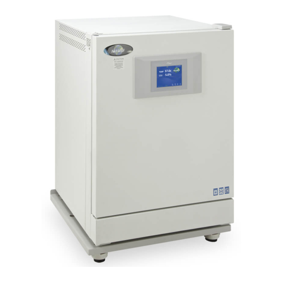
Air-Jacketed Automatic CO
NU-5710, NU-5720, NU-5731, NU-5741
NU-5710E NU-5720E, NU-5731E, NU-5741E
Operation and Maintenance Manual
November 2018
Revision 4
For 115 Vac, 50/60 Hz Only
Manufactured By:
2100 Fernbrook Lane
Plymouth, MN 55447
Toll-Free: 1-800-328-3352
In Minnesota: (763)-553-1270
Fax: (763)-553-0459
Incubator
2
Models
Series 3
NuAire, Inc.
Page 1 of 64
Advertisement
Table of Contents

Related Manuals for NuAire NU-5710


Summary of Contents for NuAire NU-5710
- Page 1 Air-Jacketed Automatic CO Incubator Models NU-5710, NU-5720, NU-5731, NU-5741 NU-5710E NU-5720E, NU-5731E, NU-5741E Operation and Maintenance Manual November 2018 Revision 4 Series 3 For 115 Vac, 50/60 Hz Only Manufactured By: NuAire, Inc. 2100 Fernbrook Lane Plymouth, MN 55447 Toll-Free: 1-800-328-3352...
-
Page 2: Table Of Contents
BCD-18320 ..............Tubing Diagram BCD-18317 ..............Incubator Right Hinge Door Assy BCD 18321 ..............Incubator Left Hinge Door Assy ELECTRICAL SCHEMATICS BCD-17630 ..............Electrical Schematic, NU-5710/E BCD-18007 ..............Main Control Board Electrical Schematic OM0249 Page 2 of 64 Rev 4 June/2020... -
Page 3: Incubator
Sterility Reliability Like all NuAire equipment, this Incubator has been designed to provide the highest quality standards of performance with matching computer technology, precise temperature control, and CO gas control system combining state-of-the-art technology with years of design, quality, and manufacturing experience. - Page 4 Keep these operating instructions close to the unit so that safety instructions and important information are always accessible. • Should you encounter problems that are not detailed adequately in the operating instructions, please contact your NuAire Representative or NuAire technical Services. OM0249 Page 4 of 64 Rev 4 June/2020...
- Page 5 1.9 Explanation of symbols Symbol (in text box) Description (in text box) Safety alert symbol indicates a potentially hazardous WARNING situation which, if not avoided, could result in death of serious injury. Safety alert symbol indicates a potentially hazardous CAUTION situation which, if not avoided, may result in minor or moderate injury.
- Page 6 Performance Parameters and Features • Both the interior and exterior of the DHD are constructed of 18 to 16-gauge steel. The interior is highly polished type 304 L 16 gage stainless steel, using crevice-free construction. All exposed edges are deburred to insure no sharp edges. The exterior is cold rolled 16 &...
- Page 7 Models & Features 3.1 Invitrocell DHD (heated decontamination) all Models. 3.2 Dimensions (see also Specification Drawing BCD-18412) Overall Dimensions - inches (mm): Model NU-5710/E thru NU-5741/E Height: Exterior: 36.188 inches (894 mm) Width: 25.500 inches (648 mm) Depth: 27.500 inches (699 mm) Foot print: 22.625 inches (575 mm) wide x 20.825 inches 530 mm) deep...
- Page 8 Relative Humidity Control: Available on NU-5720 and NU-5741 Performance Determined with O₂ Set Point @ 21.0% • RH Range: Low is ambient dependent to 95% maximum (default 90%) (0.0 set point idles the system) RH Accuracy: +5% / -3% • •...
- Page 9 OM0249 Page 9 of 64 Rev 4 June/2020...
- Page 10 4.0 Test Performance & Procedures All equipment is thoroughly inspected at the NuAire Factory at the time of shipment. Quality control is maintained by constant surveillance over the product, beginning at the receipt of purchased material and concluding with a final inspection, which certifies the Incubator performance to the specifications.
- Page 11 However, damage can occur in any shipment and the following paragraph outlines those steps you should take on receipt of a NuAire Incubator to be sure that if damage has occurred, the proper claims and actions are taken immediately.
- Page 12 Shelves Incubator is shipped with the shelves installed. The shelf mounted water pan is also in place that option is ordered. NuAire recommends decontaminating all surfaces within the interior chamber, glass door, and outer door with gasket. They can be wiped down with a disinfectant of 70 percent alcohol or similar non-corrosive antimicrobial agent.
- Page 13 OM0249 Page 13 of 64 Rev 4 June/2020...
- Page 14 7.4 Electrical The electrical supply circuit to the Incubator must conform to all national and local electrical codes. Consult the serial-data plate, located at the front of the right side of the Incubator, for voltage, cycle, phase, and ampere requirements before making connection. Plug the power cord securely into a grounded power source. VOLTAGE SHOULD NOT VARY MORE THAN 10% FROM SERIAL PLATE RATINGS.
- Page 15 CO pressure to the Incubator. Some single stage CO pressure regulators have two gauges. USE A TWO-STAGE REGULATOR. All NuAire Incubators use CO in such quantities that precise metering of CO input pressure is important for maximum performance.
- Page 16 7.7 Removing the cable tie used to secure the air pump for shipping: 7.8 Setting up the access port: When utilizing the access port do not block or restrict the relief holes in the center of the port plug. Blocking this venting can cause performance issues for the incubator.
- Page 17 Using the water pan supplied with the incubator and with a 5.0% CO₂ set point. NU-5710: After a 15 second door opening RH recovers to 90% of what the RH level was prior to opening the door for 15 seconds in 20-40 minutes on average.
-
Page 18: Control System Introduction
NOTE: DO NOT SEAL OR RESTRICT THE OPENING IN THE PORT PLUG. THIS IS A PRESSURE RELIEF FOR THE CHAMBER. 8.3 Control System Introduction The NuAire Incubator Control Electronics system is designed to serve the control requirements of the Incubator chamber. Temperature, CO levels in all models and RH & O in available models are controlled by preset values to provide the optimum conditions for culture growth within a chamber. - Page 19 NuTouch LCD menu system is accomplished through the following methods: • Touching a “graphic” Icon like the NuAire Logo in the Main Screen which access the System Settings menu, or lead you to an Enter Password screen when a password has been established.
- Page 20 8.3.5 Functioning accessed from the System Settings screen: The “System Settings” menu screen can be accessed from the “Main Screen” by touching the NUAIRE logo: Environmental Set-Points: Allows adjustment of Temperature, CO , Door, and Perimeter heater power level settings.
- Page 21 Password” menu in the System Settings menu screen. Once initiated, a four digit number must be entered, then re-entered for verification. 8.3.8 Standard remote communication capability The NU-5710 Incubator comes equipped with the following remote communication tools: USB Output of daily, weekly & monthly performance logs and an event log that indicates when alarms, •...
-
Page 22: Nutouch Display Screen
8.4.7 Power interrupted notification Indicates when a power interruption has occurred. This can be a power outage or turning the incubator off then on again. Responding by touching the text will bring the NuAire Logo back. 8.4.8 Maintenance Required Notice The Maintenance required notice appears in the middle of the right side of the screen indicating that either the RH water tank needs to be filled or that it is time to check the capsule filter in the Sensor bay. -
Page 23: Rear Component Panel
8.5 Rear Component Panel Detail The rear control panel contains the following functions (see also BDC-15170) 8.5.1 Power Cord The power cord is 6.5-foot (2 m) in length, type “SVT” molded plug, allowing for long life and easy cleaning. 8.5.2 Circuit Breaker All control electronics are protected with a circuit breaker that may trip at 110% of load rating, but will trip at 145% of load rating in less than 2 seconds. - Page 24 OM0249 Page 24 of 64 Rev 4 June/2020...
-
Page 25: Front Component Panel
8.6 Front Component Panel The front component panel contains the following functions. See BCD-15180 8.6.1 RH Fill Port (Available on models NU-5720 and NU-5741) The RH evaporator tank is filled through the port that has the red plug (w O-ring) screwed in it. Because of the pressure in the evaporator tank during an RH injection the O-Ring must seal against the top of the fill port. - Page 26 OM0249 Page 26 of 64 Rev 4 June/2020...
- Page 27 (see Section 11.0). 8.8 Standby Mode Operator Interactions The NuAire incubator automatically enters the standby mode when necessary. There is no action required by the user to enter this mode.
- Page 28 8.8.1.3 Default Set points Temperature 37.0 C All Models Note 1: A set point of 0 (zero) will put the system into an Idle state where it does not control and all alarms are CO₂ 5.0% All Models inhibited. The sensor remains active and reports the level of gas/RH in the chamber.
- Page 29 8.9.1 Diagnostic Mode To initiate the diagnostic mode, perform the following from the ‘Main’ screen: Select the NuAire Logo to enter “System Settings” • • Select “Service Settings” and enter 9876, and then hit enter (ENT) •...
- Page 30 The paragraphs on the following page provide a more complete description of the diagnostics listed above. The Diagnostic screen is shown to the right of each of the control systems Temperature, CO , RH & O and the General category for your reference. Once entered, the Diagnostics screen will display the calibrated and uncalibrated values of the given function and all related components.
- Page 31 RH Control Diagnostics functioning 1. RH Sensor This function displays the current value of the chambers RH sensor from 0 to 100%. It shows both the claibrated value shown in the display screen and un-calibrated sensor signal. 2. RH Inject Solenoid This function indicates the on/off (default off) state of the RH Inject solenoid valve and allows the activation of it.
- Page 32 Format: Option (Default, Minimum/Maximum) All the options for the NU-5710 Incubator use this same format. The default is set at the factory and can be restored in the field with a Master or a Factory reset command. On the following pages, there is a short description of each Option with its Default/Minimum/Maximum setting, followed by a more detailed description.
- Page 33 The following paragraphs provide a more complete description of the Optional configuration parameters listed above. Temperature 1. Maximum Above Set point This value determines the maximum deviation, measured in (°C) that the chamber is permitted to rise above set point, once it is reached before an alarm condition is declared. An alarm condition will cause the chamber to enter a safe condition where no power is enabled to any of the system output controls until the situation is rectified.
- Page 34 Relative Humidity 1. System Enable (Enabled/disabled) on models NU-5720 and NU-5741 Is located in the bottom right of the screen This function will enable or disable the RH system. If the system is Enabled it will be displayed in the MAIN screen. If it is disabled it will not be displayed in the Main or Option/Settings screen for the RH system: System Enabled (with check mark) means the System is enabled...
- Page 35 Screen Lock button (default Main Screen Unlocked). Pressing this button will change it to “Main screen Locked” (Lockout = 1). This puts a “Press to unlock” button on the Nuaire Logo in the Main screen. This feature stops accidental screen changes by brushing the touch screen. You must press and hold (2 seconds) until the message disappears which unlocks the main screen so that you can navigate into;...
-
Page 36: Resetting The Electronic Software
Setting the model number sets the following function: All Nuaire customers will press Nuaire in the “Choose Company” Screen. This will bring up the • Nuaire logo in the main screen. . All other customers will press the appropriate company button to bring up the identifiers specific to that company. - Page 37 Model number NU-5700 and NU-5710 and E or D models • Enables Temperature and CO the only control systems available on this model Chooses the algorithm suited for low watt heating of the chamber Supresses the decon button in the “Systems Settings” screen Loads the model number in the System information screen •...
-
Page 38: Chamber Temperature Calibration
9.1 Chamber Temperature Calibration The DH’s TEMPERATURE CALIBRATION MUST BE PERFORMED WITHIN 1°C OF THE PLANNED OPERATING TEMPERATURE. Normally, 37.0°C is the most common set point. To initiate the procedure, turn on the incubator via the power switch on the back panel. The default set point is 37.0°C; enter “Environmental Set Points” and adjust if desired Let the unit stabilize for 8 to 12 hours. -
Page 39: Setting Air Injections
shell next to the glass door gasket. If calibration is required, simply perform the procedure as stated below. As stated earlier the door and perimeter heaters operate on a base duty cycle calculated for the chamber temperature set point being used. In the door and perimeter heater (adjustment) screen “0.0” = the calculated base duty cycle. Adjusting the value up or down will increase or decrease the percent of power to each heater in 0.1% increments. -
Page 40: Calibration
section of the Service Settings menu. The default is 10-second injections every 1 minute. Start by increasing the length of the injection by a few seconds at a time then increase the frequency if needed. If the humidity in the chamber is less than desired, reduce the Air Inject Time. -
Page 41: Calibration
• Enter CO calibrations by means of Service Settings • Select the “CO Open Door Zero Span” text • Follow on screen instructions The CO inject rate is automatically calculated from the CO injection made during the span calibration making it unnecessary to run the separate “Injection Calibration”. - Page 42 When unit chamber has stabilized at the operational temperature, CO %, the RH set point has been chosen and with water in the tank the heater has been powered for at least 60 minutes ensuring it is up to temperature. Allow the RH system to achieve set point and stabilize there for at least 30 minutes.
-
Page 43: Heated Decon Cycles
DHD Chamber The chamber maintenance is up to the discretion of the owner and the extent of cleanliness and sterility desired. The shelves and bracket supports are all removable and autoclavable. The interior should be wiped down with an appropriate disinfectant such as 70% ISOPROPYL ALCOHOL or equivalent. ... - Page 44 THE HEATED DECONTAMINATION CYCLES NuAire gives the lab professional the choice of the 2 most commonly accepted, heated decontamination cycles available. They are a 95°C humidified cycle and a 145°C dry cycle. To choose, the user goes to the System Settings menu and pushes the Decon button in the lower right hand of the display.
- Page 45 DRY 145° C DECON CYCLE TIME (HRS:MIN:SEC) Note: RH and O₂ control systems will be idle during the cycle. • • Protection of the CO and O₂ sensors during the heated cycle is automatic. RH sensor must be removed from all models equipped with RH control the as stated in the Preparation section and •...
- Page 46 CYCLE COMPLETE Indicates the user should: • Refill the water pan with single distilled water no purer than 1 Mega OHM in preparation to return to normal running. Note: If Decon Cycle is run as routine maintenance, it is ok to reuse the HEPA filters for the service life indicated in Section 10.
- Page 47 PREPARATION Following the prompts in the incubator display screen you will: • Remove culture cells, samples, dishes, instruments, or other user-introduced equipment from the chamber. • Wipe out all spills and materials from chamber walls, shelves, and plenums using a disinfectant of choice that is compatible with construction of the Incubator chamber and instrumentation.
- Page 48 Start the decon cycle by following the prompts on the NuTouch display screen. The decon cycle will automatically go through the following phases: HEAT UP 1 hour Complete the chamber preparation and either schedule a start time or press the Start button to start the heat up portion of the cycle.
-
Page 49: Chemical Decontamination
10.2 Chemical Decontamination of the Incubator Chamber To chemically decontaminate NuAire Incubator inner chambers, users may use the traditional formaldehyde or Chlorine Dioxide in gas form, or Vapor Phased Hydrogen Peroxide. All three of the chemicals are compatible to all parts within NuAire Incubator chambers. - Page 50 Responding to the notification: From the main screen press the NuAire Logo / Service settings / General Option / Settings / Filter Maintenance to access the Filter Maintenance Adjustments screen. In this screen you can: Extend the alarm by 1 month by pushing the Extend. Press the Exit button •...
- Page 51 Pressing the Alarm Status button, entering the correlating Alarms Menu and pressing the Silence button in the Alarms Menu will silence the audible alarm until Diagnostics is entered or another alarm becomes active. Step 2 CLEAR ERROR INDICATORS. Error indicators can be cleared by pressing the Alarm Status button and entering the Alarms Menu and pressing the Clear All button;...
- Page 52 Decon Cycle Faulty TRIAC, replace control board Decon Temp Low - Decon Time Out Faulty chamber heater contact NuAire Technical Service. - Temp less than decon temp -10⁰ Door/Perimeter heater needs to be increased with a high for 240 minutes...
- Page 53 Displayed Error Code Code Description Checks and Corrections Perform RH sensor calibration - RH over set point beyond the alarm Check injection solenoid for leaking valve RH Level High limit Check sensor & moisture barrier in sensor cap for moisture Perform RH sensor calibration Check RH tank for water level if low check Float switch in - RH Level is below the set point...
- Page 54 Stops trying to write to USB memory Universal Serial Bus Error several tries stick after several tries USB port not functioning contact Nuaire technical service Increase Door heater duty cycle in 5% increments or less On Glass Door at a time...
- Page 55 12.1 Remote Alarm Contacts The NuAire DHD Incubator contains a set of contact points to connect to a remote alarm system. The contacts are located on the rear panel (see page 14). The contacts are housed in a modular (RJ-11) telephone jack and rated for (30V at 1 Amp).
- Page 56 When connecting external accessories or components to the system, CAUTION attach only components that have been tested and certified for compliance to UL/IEC 60601-1 or UL/IEC 60950 13.0 Electrical/Environmental Requirements 13.1 Electrical Models: NU-5710, NU-5720, NU-5731 and NU-5741 Domestic Units: 115V, 50/60Hz, 1 Phase, 8.5 Amps “E” Units:...
- Page 57 13.8 Heat Rejection: 14 BTU/Minutes. 14.0 Disposal and Recycle Incubators that are no longer in use and are ready for disposal contain reusable materials. ALL components with the exception of the HEPA filters may be disposed and/or recycled after they are known to be properly disinfected. ...
- Page 58 OM0249 Page 58 of 64 Rev 4 June/2020...
- Page 59 OM0249 Page 59 of 64 Rev 4 June/2020...
- Page 60 OM0249 Page 60 of 64 Rev 4 June/2020...
- Page 61 OM0249 Page 61 of 64 Rev 4 June/2020...
- Page 62 OM0249 Page 62 of 64 Rev 4 June/2020...
- Page 63 OM0249 Page 63 of 64 Rev 4 June/2020...
- Page 64 OM0249 Page 64 of 64 Rev 4 June/2020...
Need help?
Do you have a question about the NU-5710 and is the answer not in the manual?
Questions and answers