Table of Contents
Advertisement
Quick Links
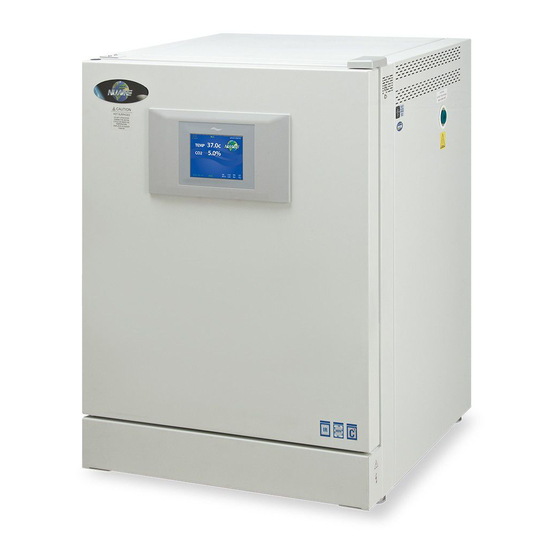
Air-Jacketed DH Invitrocell CO
Incubator
2
Models
NU-5700 (Series3)
NU-5700E (Series 3)
Operation and Maintenance Manual
November 2018
Revision 3
For 115 Vac, 50/60 Hz Only
Manufactured By:
NuAire, Inc.
2100 Fernbrook Lane
Plymouth, MN 55447
Toll-Free: 1-800-328-3352
In Minnesota: (763)-553-1270
Fax: (763)-553-0459
OM0250
Page 1 of 54
Rev 3 November/2018
Advertisement
Table of Contents

Subscribe to Our Youtube Channel
Related Manuals for NuAire 3 Series


Summary of Contents for NuAire 3 Series
- Page 1 NU-5700 (Series3) NU-5700E (Series 3) Operation and Maintenance Manual November 2018 Revision 3 For 115 Vac, 50/60 Hz Only Manufactured By: NuAire, Inc. 2100 Fernbrook Lane Plymouth, MN 55447 Toll-Free: 1-800-328-3352 In Minnesota: (763)-553-1270 Fax: (763)-553-0459 OM0250 Page 1 of 54...
-
Page 2: Table Of Contents
Air-Jacketed DHD Invitrocell CO₂ Incubator Operation and Maintenance Manual NU-5700 & NU-5700E Table of Contents Section No. 1 ..........General Description Section No. 2 ..........Performance Parameters and Features Section No. 3 ..........Models & Features Section No. 4 ..........Test Performance & Procedures Section No. -
Page 3: Sterility
Sterility Reliability Like all NuAire equipment, this Incubator has been designed to provide the highest quality standards of performance with matching computer technology, precise temperature control, and CO gas control system combining state-of-the-art technology with years of design, quality, and manufacturing experience. - Page 4 Keep these operating instructions close to the unit so that safety instructions and important information are always accessible. Should you encounter problems that are not detailed adequately in the operating instructions, please contact your • NuAire Representative of NuAire technical Services. OM0250 Page 4 of 54 Rev 3 November /2018...
- Page 5 1.9 Explanation of symbols Symbol Description Safety alert symbol indicates a potentially hazardous WARNING situation which, if not avoided, could result in death of serious injury. Safety alert symbol indicates a potentially hazardous CAUTION situation which, if not avoided, may result in minor or moderate injury.
- Page 6 Performance Parameters and Features • Both the interior and exterior of the DH are constructed of 18 to 16-gauge steel. The interior is highly polished type 304 L 16 gage stainless steel, using crevice-free construction. All exposed edges are deburred to insure no sharp edges. The exterior is cold rolled 16 &...
- Page 7 3.0 Models & Features 3.1 Dimensions (see also Specification Drawing BCD-18412) Overall Dimensions - inches (mm): Model NU-5700/E Height: Exterior: 36.188 inches (894 mm) Width: 25.500 inches (648 mm) Depth: 27.500 inches (699 mm) Foot print: 22.625 inches (575 mm) wide x 20.825 inches 530 mm) deep Height: Interior: 24.000 inches (610 mm) Width:...
- Page 8 3.3 Standard Items Packed With Unit Four (4) stainless steel shelves • • Eight (8) stainless steel shelf brackets One (1) water pan • • Gas supply tube(s) • Access port plug - vented One (1), 2 meter (6.5 ft.) electrical cord 10 Amp 18awg with 70⁰C rated jacket * •...
- Page 9 OM0250 Page 9 of 54 Rev 3 November /2018...
- Page 10 4.0 Test Performance & Procedures All equipment is thoroughly inspected at the NuAire Factory at the time of shipment. Quality control is maintained by constant surveillance over the product, beginning at the receipt of purchased material and concluding with a final inspection, which certifies the Incubator performance to the specifications.
- Page 11 However, damage can occur in any shipment and the following paragraph outlines those steps you should take on receipt of a NuAire Incubator to be sure that if damage has occurred, the proper claims and actions are taken immediately.
- Page 12 7.3 Interior Chamber, Shelf & Water Pan preparation. Chamber & Shelves Incubator is shipped with the shelves installed. A shelf mounted water pan is also available. NuAire recommends decontaminating all surfaces within the interior chamber, glass door, and outer door with gasket. They can be wiped down with a disinfectant of 70 percent alcohol or similar non-corrosive antimicrobial agent.
- Page 13 OM0250 Page 13 of 54 Rev 3 November /2018...
- Page 14 7.4 Electrical The electrical supply circuit to the Incubator must conform to all national and local electrical codes. Consult the serial-data plate, located at the front of the right side of the Incubator, for voltage, cycle, phase, and ampere requirements before making connection. Plug the power cord securely into a grounded power source. VOLTAGE SHOULD NOT VARY MORE THAN 5% FROM SERIAL PLATE RATINGS.
- Page 15 0 to 2 BAR (100 PSI or 6 BARS maximum). This gauge will indicate the actual CO pressure to the Incubator. Some single stage CO pressure regulators have two gauges. USE A TWO-STAGE REGULATOR. All NuAire Incubators use in such small quantities that precise metering of CO input pressure is important for maximum performance.
- Page 16 7.7 Remove the cable tie used to secure the air pump for shipping: 7.8 Setting up the access port: When utilizing the access port do not block or restrict the relief holes in the center of the port plug. Blocking this venting can cause performance issues for the incubator.
- Page 17 Use mild detergent to clean the exterior of the Incubator. NOTE: NuAire does not offer any product warranty with respect to cleaning material compatibility. USE AT YOUR OWN RISK! The information provided above is from raw material suppliers and known general source documents for use to develop application cleaning SOP’s.
-
Page 18: Control System Introduction
8.3 Control System Introduction The NuAire Incubator Control Electronics system is designed to serve the control requirements of the Incubator chamber. Temperature and CO levels are controlled by preset values to provide the optimum conditions for culture growth within a chamber. - Page 19 NU-Touch LCD menu system is accomplished through the following methods: • Touching a “graphic” Icon like the NuAire Logo in the Main Screen which access the System Settings menu, or lead you to an Enter Password screen when a password has been established.
- Page 20 Functioning accessed from the System Settings screen: The “System Settings” menu screen can be accessed from the “Main Screen” by touching the NUAIRE logo: Environmental Set-Points: Allows adjustment of Temperature, CO2, Door, and Perimeter heater power level settings. Note: You can also access the Environmental set points by touching any control system numerical value in the MAIN SCREEN.
- Page 21 A USB method of updating the software 8.3.8 Diagnostic and calibration assists. To access the Service Settings Menu, perform the following steps: NuAire Logo → Service Settings → 9876 Enter. You are now in the Service Settings Menu (screen). This screen provides you the capability to review and analyze numerous Incubator functions including the following: •...
- Page 22 The “Alarm Status” button indicates is triggered when a timer for a maintenance reminder runs to zero. This text appears in red just below the NuAire Logo (paragraph 8.4.2 and 8.4.3). The “Alarm Status” button and audible alarm indicates the abnormality. A catastrophic temperature control condition will de-energize the safety relay and cause the chamber to cool below the set point.
- Page 23 8.5 Rear Panel Detail The rear control panel contains the following functions (BDC-15669) 8.5.1 Power Cord The power cord is 6.5-foot (2 m) in length, type “SVT” molded plug, allowing for long life and easy cleaning. 8.5.2 Circuit Breaker All control electronics are protected with a circuit breaker that may trip at 110% of load rating, but will trip at 145% of load rating in less than 2 seconds.
- Page 24 OM0250 Page 24 of 54 Rev 3 November /2018...
-
Page 25: Front Component Panel
8.6 Front Component Panel The front component panel contains the following functions. See BCD-18316 8.6.1 CO2 Supply Filter The CO2 supply filter is installed at the factory and should be changed following the instructions found in Maintenance Section 10. 8.6.2 Air Inlet Filter - All models The Air Inlet Filter is installed at the factory and should be changed following the instructions found in Maintenance section 10. - Page 26 OM0250 Page 26 of 54 Rev 3 November /2018...
-
Page 27: Run Mode Operator Interactions
8.8 Standby Mode Operator Interactions The NuAire incubator automatically enters the standby mode when necessary. There is no action required by the user to enter this mode. All functions that put the incubator in standby mode automatically start a 10 minute timer. If the function is not interfaced through the screen on the NU-Touch display the incubator then returns to the MAIN SCREEN and switches to RUN mode. - Page 28 The diagnostic mode allows the operator to configure and/or check the Incubator for input/output signals manually and individually. To initiate the diagnostic mode, perform the following from the ‘Main’ screen: Select the NuAire Logo to enter “System Settings” • •...
- Page 29 Output/Input Diagnostic Parameter Functions Temperature 1. Safety Relay (on/off) 2. Chamber Temp. Sensor (shows current temp.) 3. Safety Temp. Sensor (shows current temp.) 4. Chamber heater Triac control (0 - 50% - 100%) 5. Door Heater Triac control (0 - 50% - 100 %) 6.
- Page 30 2. Chamber Temperature Sensor This function shows on LCD the current values, calibrated (displayed) and not calibrated of the temperature sensor controlling the chamber temperature. 3. Safety Temperature Sensor This function shows on LCD the current values, calibrated and not calibrated of the Safety temperature sensor located in the chamber.
- Page 31 This function shows on LCD the current state of the Air Pump Triac. LCD will show “ON” or “OFF” corresponding to the relay position. The triac can be manually turned On and Off. Option Configuration Parameters Format: Option (Default, Minimum/Maximum) All the options for the NU-5700 Incubator use this same format.
- Page 32 This value specifies a maximum differential, measured in temperature (°C) that the two temperature sensors may deviate from one another, or from the last read value. If this differential is exceeded, a warning LED is shown on the running chamber. If multiple sensors fail to read within the specified limits, an alarm condition is declared.
-
Page 33: Resetting The Electronic Software
Screen Lock button (default Main Screen Unlocked). Pressing this button will change it to “Main • screen Locked” (Lockout = 1). This puts a “Press to unlock” button on the Nuaire Logo in the Main screen. This feature stops accidental screen changes by brushing the touch screen. You must press and hold (2 seconds) until the message disappears which unlocks the main screen so that you can navigate into;... - Page 34 If the Model Number or the Serial Number need to be re-input for any reason the following steps should be taken: Setting the model number sets the following function: All NuAire customers will press NuAire in the “Choose Company” Screen. This will bring up the •...
-
Page 35: Chamber Temperature Calibration
The final change that is requested is the clock. It should not have been reset. • As long as the date and time are correct you can cancel out of that screen to the Main screen. • If the incubator loses power the date/time will flash in green text until it is manually interfaced with. If the date and time are correct you can cancel and the display will return to the main screen. - Page 36 9.2 Door and Perimeter Duty Cycle adjustments for Temperature Calibration The Door and Perimeter heaters are run on “Base Duty Cycle” calculations that are automatically increased or decreased to run in accordance with the chamber temperature at a chosen set point. These duty cycles work in the controlled lab environment but due to the many variables involved in temperature control there is also a manual adjustment.
- Page 37 9.3 Setting Air Injections If there is still some undesired condensation in the chamber when the door and perimeter heaters are set for the desired result, the air injections can be adjusted. There is a control for length of the air injection labeled, Air Inject Time, and the frequency that air is injected called, Air Inject Cycle.
- Page 38 9.4.3 Open Door CO Sensor Calibration Routine • Attach independent CO2 monitoring device to the sample port on the front of the unit Enter CO2 calibrations by means of Service Settings • • Select the “CO2 Open Door Zero Span” text Follow on screen instructions •...
-
Page 39: Chemical Decontamination
SUCH MATERIAL IS HARMFUL TO THE POLISHED STAINLESS STEEL. NOTE: NuAire does not offer any product warranty with respect to cleaning material compatibility. USE AT YOUR OWN RISK! The information provided above is from raw material suppliers and known general source documents for use to develop application cleaning SOP’s. -
Page 40: Shutting Down The Incubator
Blocking solenoid will be turned “ON” which will bypass the CO2 and O2 sensors in the circulation system. Both systems will be put in standby mode meaning they will not control or alarm while in this mode. “Power Loss Recovery” shows in place of “RUN” in the main screen. Heaters and Air Pump run as normal. - Page 41 Responding to the notification: From the main screen press the NuAire Logo / Service settings / General Option / Settings / Filter Maintenance to access the Filter Maintenance Adjustments screen. In this screen you can: Extend the alarm by 1 month by pushing the Extend button. Press the •...
- Page 42 Step 2 CLEAR ERROR INDICATORS. Error indicators can be cleared by pressing the Alarm Status button and entering the Alarms Menu and pressing the Clear All button; if the error is still present the indicator will return when the alarm time reaches 0. Step 3 MONITOR REOCCURRENCE OF ERROR INDICATORS.
- Page 43 Temp Under Set Point, Faulty TRIAC, replace control board during normal running and in Faulty chamber heater contact NuAire Technical Service. Door/Perimeter heater needs to be increased with a high temperature set-point in a low ambient temperature -Sensor temperature (differential) Check temperature sensor calibration error normal running.
- Page 44 Stops trying to write to USB Universal Serial Bus Error several tries memory stick after several tries USB port not functioning contact Nuaire technical service Increase Door heater duty cycle in 5% increments or less at a On Glass Door time...
- Page 45 12.1 Remote Alarm Contacts The NuAire DH Incubator contains a set of contact points to connect to a remote alarm system. The contacts are located on the rear panel (see page 14). The contacts are housed in a modular (RJ-11) telephone jack and rated for (30V at 1 Amp).
- Page 46 13.0 Electrical/Environmental Requirements 13.1 Electrical (Supply voltage fluctuations not to exceed +/- 10%) NU-5700 115V, 50/60Hz, 1 Phase, 4.1 Amps NU-5700E 230V, 50/60Hz, 1 Phase, 2.1 Amps Start Up Power 435 Watts Running Power 200 Watts 13.2 Operational Performance (for indoor use only) Environment Temperature Range: 60°F-85°F (15.5°C –...
- Page 47 13.8 Heat Rejection: 14 BTU/Minute. 14.0 Disposal and Recycle Incubators that are no longer in use and are ready for disposal contain reusable materials. ALL components with the exception of the HEPA filters may be disposed and/or recycled after they are known to be properly disinfected. ...
- Page 48 OM0250 Page 48 of 54 Rev 3 November /2018...
- Page 49 OM0250 Page 49 of 54 Rev 3 November /2018...
- Page 50 OM0250 Page 50 of 54 Rev 3 November /2018...
- Page 51 OM0250 Page 51 of 54 Rev 3 November /2018...
- Page 52 OM0250 Page 52 of 54 Rev 3 November /2018...
- Page 53 OM0250 Page 53 of 54 Rev 3 November /2018...
- Page 54 OM0250 Page 54 of 54 Rev 3 November /2018...
Need help?
Do you have a question about the 3 Series and is the answer not in the manual?
Questions and answers