Table of Contents
Advertisement
Available languages
Available languages
Quick Links
SC 94 05
SC 94 05
SC 94
SC 94 00
00 -4 8S
-4 8S -E
1
1
-E
1
1
2
2
3
3
4
4
5
5
St at us
St at us
SC 94 00
-8 C- E
2
2
St at us
St at us
SC 94 00
SC 94 00
3
3
1
1
2
2
3
3
4
4
5
5
St at us
St at us
SC9405 SERIES CORE SWITCHES
SC9405-SERIE CORE SWITCHES
SWITCHS CENTRAUX DE LA SÉRIE SC9405
Quick Start Guide
Quick Start Anleitung
Guide de Démarrage Rapide
6
6
7
7
8
8
9
9
10
10
11
11
12
12
13
13
14
14
15
15
16
16
17
17
18
18
19
19
20
20
21
21
22
22
23
23
24
24
25
25
26
26
27
27
28
28
29
29
On =L
On =L
ink Fla
ink Fla
sh ing
sh ing
=A CT
=A CT
Gr ee n=
Gr ee n=
10 00 M
10 00 M/
10 G
6
6
1
1
7
7
8
8
9
9
10
10
2
2
11
11
12
12
13
13
3
3
14
14
15
15
16
16
4
4
17
17
18
18
Q SF P2
Q SF P2
19
19
20
20
8
8
5
5
21
21
22
22
23
23
6
6
24
24
25
25
26
26
27
27
28
28
29
29
On =L
On =L
ink Fla
ink Fla
sh ing
sh ing
=A CT
=A CT
Gr ee n=
Gr ee n=
10 00 M
10 00 M
Ye llo w=
Ye llo w=
10 0M
10 0M
V1.0
E S D
St atu
s
Pr im ar
y
Al ar m
FU NC
MG MT
M
M
M
Co ns ole
30
30
31
31
St atu
1
s
1
1
32
32
Pr im ar
y
Al ar m
33
33
FU NC
34
34
35
35
36
36
37
37
MG MT
38
38
39
39
40
40
Co ns ole
41
41
42
42
43
43
M
M
M
44
44
45
45
2
2
2
46
46
47
47
48
48
1
1
7
7
30
30
8
8
31
31
32
32
33
33
34
34
35
35
36
36
2
2
37
37
38
38
39
39
40
40
41
41
42
42
43
43
44
44
45
45
46
46
47
47
48
48
3
3
Advertisement
Table of Contents

Related Manuals for FS SC9405 Series


Summary of Contents for FS SC9405 Series
- Page 1 10 00 M 10 00 M Ye llo w= Ye llo w= 10 0M 10 0M SC9405 SERIES CORE SWITCHES SC9405-SERIE CORE SWITCHES SWITCHS CENTRAUX DE LA SÉRIE SC9405 Quick Start Guide V1.0 Quick Start Anleitung Guide de Démarrage Rapide...
- Page 2 Introduction Thank you for choosing SC9405 Series Core Switches. This guide is designed to familiarize you with the layout of the switches and describes how to deploy them in your network. Status Primary Alarm FUNC MGMT Console E S D...
-
Page 3: Front Panel Ports
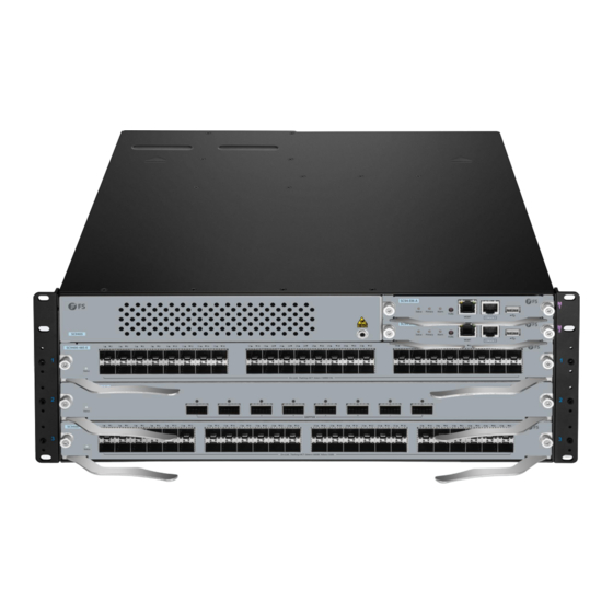
Hareware Overview Front Panel SC9405 Status Primary Alarm FUNC MGMT Console E S D SC9405 SC9405 Status Primary Alarm FUNC MGMT Console SC9400-48S-E SC9400-48S-E Status Status On=Link Flashing=ACT Green=1000M On=Link Flashing=ACT Green=1000M/10G SC9400-8C-E Status Status QSFP28 QSFP28 SC9400 SC9400 Status Status On=Link Flashing=ACT Green=1000M Yellow=100M On=Link Flashing=ACT Green=1000M Yellow=100M... - Page 4 Ports Description For storing logs, host version, alarms and other diagnosis information, facilitating online upgrade of switch software and storage of logs Using the RS-232 interface level and standard RJ-45 connector for system commissioning, Console configuration, maintenance, management, and host software loading MGMT 10/100/1000BASE-T Ethernet port, using the RJ-45 connector to load programs SC9400-48F-E...
-
Page 5: Front Panel Leds
Front Panel LEDs SC94-EM-A Primary MGMT Status Status Primary Alarm FUNC MGMT Console Status Primary Alarm FUNC MGMT Console Alarm LEDs State Description Off The module is powered off. Blinking green Initialization is in progress. Continuous blinking indicates errors. Status Solid green The switch is operational. - Page 6 SC9400-48F-E SC9400-48S-E SC9400-48S-E Status Status On=Link Flashing=ACT Green=1000M On=Link Flashing=ACT Green=1000M/10G Status Link/ACT LEDs State Description Off The module is powered off. Blinking green Initialization is in progress. Continuous blinking indicates errors. Status Solid green The switch is operational. Solid red The module is faulty.
-
Page 7: Back Panel
SC9400-8C-E SC9400-8C-E Status Status QSFP28 QSFP28 Status Link/ACT LEDs State Description Off The module is powered off. Blinking green Initialization is in progress. Continuous blinking indicates errors. Status Solid green The switch is operational. Solid red The module is faulty. The port link is NOT connected. -
Page 8: Installation Requirements
Installation Requirements Before installation, make sure that you have the following conditions ready: Phillips screwdriver. Standard-sized, 19" wide rack with a minimum of 1U height available in 4-post form hold. Category 5e or higher RJ-45 Ethernet cables for connecting network devices. Site Environment Make sure that the temperature of installation site is maintained at 0°~50°C. -
Page 9: Cabinet Mounting
NOTE: Make sure the antistatic wrist strap is grounded well and wear the antistatic wrist strap in this step and the followings. Cabinet Mounting 1. Mount the cabinet at the designed location as planned. 2. Install the appropriate cable management bracket and cables. 3. -
Page 10: Mounting The Switch To A Cabinet
Mounting the Switch to a Cabinet 1. Locate the position on the bracket for installing the slide rail. And locate the position on the other bracket through the carrying plane. 2. Install seven cage nuts on the marked square holes on each bracket. Status Primary Alarm... -
Page 11: Grounding The Switch
CAUTION: Usually, reserve at least 10mm between the front panel of the equipment and that of the cabinet after installation. Before mounting into a cabinet, address the following conditions: 1. Prepare the equipment and move it to the place near the cabinet where you can handle it easily. -
Page 12: Connecting The Power
Connecting the Power Po w er St at us 1. Loosen the captive screws on the blank panel covering the power slot at the rear of the enclosure. 2. Insert the power module into the slot along the rail until the power module clicks into place. CAUTION: 1. -
Page 13: Installing Modules
1. Install the fan tray into the fan slot in the rear panel. Note the direction identifier of the fan tray’s name to ensure the correct direction. 2. Tighten the captive screws on the fan tray with a screwdriver. CAUTION: Do not remove the fan tray forcibly. -
Page 14: Installing Swappable Interface Modules (Optional)
CAUTION: 1. Do not hold the edge or collide the components on the PCB. Do not touch the connecting finger on the modules. 2. Do not plug/unplug a supervisor module, service module or switch fabric module with force, use the ejector. 3. - Page 15 1. Turn up the handle of the module into the top bail-clasp latch. Hold both sides and push the module into place with a click sound. 2. Use the fiber optical patch cord to connect the SFP/SFP+ module to the fiber optical network. Select the patch cord with the connector corresponding to the port and the Link/ACT Status LED is on.
- Page 16 1. Turn up the handle of the module into the top bail-clasp latch. Hold both sides and push the module into place with a click sound. S C 9 4 S C 9 4 S C 9 4 S C 9 4 0 0 - 4 8 0 0 - 4 8 S - E...
-
Page 17: Connecting The Console Port
Connecting the Console Port SC 94 SC 94 SC 94 SC 94 00 -48 00 -48 St atu St atu Sta tus Prim Ala rm Res et MG MT St atu St atu Sta tus Con sol Prim SC 94 SC 94 Ala rm Res et... -
Page 18: Connecting The Usb Port
Connecting the USB Port S C 9 4 S C 9 4 S C 9 4 S C 9 4 0 0 -4 8 0 0 -4 8 S -E S -E S ta tu S ta tu St at us Pr im ar y Al ar m... - Page 19 Step 2: Set the IP address of the computer to 192.168.1.x. (“x” is any number from 2 to 254.) IE 8/9/10/11, Google Chrome, Firefox are supported admin ***** Login Step 3: Open a browser, type http://192.168.1.1, and enter the default username and password, admin/admin.
-
Page 20: Troubleshooting
Step 3: Set the parameters of the HyperTerminal: 9600 bits per second, 8 data bits, no parity, 1 stop bit and no flow control. Step 4: After setting the parameters, click Connect to enter. Troubleshooting AC Power Module Does Not Work 1. -
Page 21: Online Resources
Product Warranty FS ensures our customers that if there are any damage or faulty items due to our workmanship, we will offer a free return within 30 days from the day you receive your goods. This excludes any custom made items or tailored solutions. - Page 22 Einführung Vielen Dank, dass Sie sich für Core Switches der Serie SC9405 entschieden haben. Diese Anleitung soll Sie mit dem Aufbau der Switches vertraut machen und beschreibt, wie Sie sie in Ihrem Netzwerk einsetzen können. Status Primary Alarm FUNC MGMT Console E S D SC9405...
- Page 23 Hardware-Übersicht Vorderseite SC9405 Status Primary Alarm FUNC MGMT Console E S D SC9405 SC9405 Status Primary Alarm FUNC MGMT Console SC9400-48S-E SC9400-48S-E Status Status On=Link Flashing=ACT Green=1000M On=Link Flashing=ACT Green=1000M/10G SC9400-8C-E Status Status QSFP28 QSFP28 SC9400 SC9400 Status Status On=Link Flashing=ACT Green=1000M Yellow=100M On=Link Flashing=ACT Green=1000M Yellow=100M Beschreibung Steckplätze für Supervisor-Module...
- Page 24 Port Beschreibung Zur Speicherung von Protokollen, Host-Versionen, Alarmen und anderen Diagnoseinformationen, zur Erleichterung der Online-Aktualisierung der Switch-Software und zur Speicherung von Protokollen Verwendung der RS-232-Schnittstellenebene und des Standard-RJ-45-Anschlusses für die Console Inbetriebnahme, Konfiguration, Wartung, Verwaltung und das Laden von Host-Software 10/100/1000BASE-T-Ethernet-Port, über den RJ-45-Anschluss können Programme geladen MGMT werden...
-
Page 25: Leds An Der Vorderseite
LEDs an der Vorderseite SC94-EM-A Primary MGMT Status Status Primary Alarm FUNC MGMT Console Status Primary Alarm FUNC MGMT Console Alarm Beschreibung Status Das Modul ist ausgeschaltet. Die Initialisierung ist im Gange. Kontinuierliches Blinken zeigt Fehler Blinkt grün Status Der Switch ist betriebsbereit. Durchgehend grün Das Modul ist defekt. - Page 26 SC9400-48F-E SC9400-48S-E SC9400-48S-E Status Status On=Link Flashing=ACT Green=1000M On=Link Flashing=ACT Green=1000M10G Status Link/ACT Status Beschreibung Das Modul ist ausgeschaltet. Die Initialisierung ist im Gange. Kontinuierliches Blinken zeigt Fehler Blinkt grün Status Durchgehend grün Der Switch ist betriebsbereit. Durchgehend rot Das Modul ist defekt. Der Port-Link ist NICHT verbunden.
- Page 27 SC9400-8C-E SC9400-8C-E Status Status QSFP28 QSFP28 Status Link/ACT Status Beschreibung Das Modul ist ausgeschaltet. Die Initialisierung ist im Gange. Kontinuierliches Blinken zeigt Fehler Blinkt grün Status Durchgehend grün Der Switch ist betriebsbereit. Durchgehend rot Das Modul ist defekt. Der Port-Link ist NICHT verbunden. Durchgehend grün Link/ACT Der Port ist verbunden.
-
Page 28: Montage Des Switches
Installationsvoraussetzungen Stellen Sie vor der Installation sicher, dass Sie die folgenden Voraussetzungen erfüllen: Kreuzschlitzschraubendreher. 19"-Rack in Standardgröße mit einer Mindesthöhe von 1 HE, verfügbar in Form eines 4-Säulen-Racks. RJ-45-Ethernet-Kabel der Kategorie 5e oder höher für den Anschluss von Netzwerkgeräten. Standortumgebung Achten Sie darauf, dass die Temperatur am Aufstellungsort zwischen 0°C und 50°C gehalten wird. - Page 29 HINWEIS: Achten Sie darauf, dass das Antistatik-Armband gut geerdet ist, und tragen Sie das Antistatik-Armband in diesem und den folgenden Schritten. Montage des Gehäuses 1. Montieren Sie den Schrank wie geplant an dem vorgesehenen Standort. 2. Installieren Sie die entsprechende Kabelführungsbügel und die Kabel. 3.
- Page 30 Montage des Switches in einem Schaltschrank 1. Ermitteln Sie die Position auf der Halterung für die Montage der Gleitschiene. Ermitteln Sie die Position auf der anderen Halterung mit Hilfe der Tragfläche. 2. Bringen Sie sieben Käfigmuttern an den markierten quadratischen Löchern an jeder Halterung an. Status Primary E S D...
- Page 31 ACHTUNG: Halten Sie in der Regel einen Abstand von mindestens 10mm zwischen der Frontplatte des Geräts und der des Schranks nach der Installation ein. Bevor Sie das Gerät in einen Schrank einbauen, sollten Sie die folgenden Bedingungen erfüllen: 1. Bereiten Sie das Gerät vor und bringen Sie es zu einen Ort in der Nähe des Schranks, an dem Sie es leicht handhaben können.
-
Page 32: Anschließen Der Stromversorgung
Anschließen der Stromversorgung Po w er St at us 1. Lösen Sie die unverlierbaren Schrauben an der Blindplatte, die den Stromanschluss an der Rückseite des Gehäuses abdeckt. 2. Schieben Sie das Netzmodul entlang der Schiene in den Steckplatz, bis es einrastet. ACHTUNG: 1. - Page 33 1. Setzen Sie den Lüftereinschub in den Lüfterschlitz auf der Rückseite ein. Achten Sie auf die Richtungsangabe in der Bezeichnung des Lüftereinschubs, um die richtige Richtung zu gewährleisten. 2. Ziehen Sie die unverlierbaren Schrauben des Lüfterfachs mit einem Schraubendreher fest. ACHTUNG: Entfernen Sie den Lüftereinschub nicht gewaltsam.
- Page 34 ACHTUNG: 1. Halten Sie sich nicht an der Kante fest und stoßen Sie sich nicht an den Komponenten auf der Platine. Berühren Sie nicht die Verbindungsfinger an den Modulen. 2. Stecken Sie ein Supervisor-Modul, ein Service-Modul oder ein Switch Fabric-Modul nicht mit Gewalt ein/aus, sondern verwenden Sie den Auswerfer.
- Page 35 1. Drehen Sie den Griff des Moduls nach oben in die obere Verriegelung des Bügels. Halten Sie beide Seiten fest und drücken Sie das Modul mit einem Klickgeräusch in die richtige Position. 2. Verwenden Sie das Glasfaser-Patchkabel, um das SFP/SFP+-Modul mit dem Glasfasernetzwerk zu verbinden.
- Page 36 1. Drehen Sie den Griff des Moduls nach oben in die obere Verriegelung des Bügels. Halten Sie beide Seiten fest und drücken Sie das Modul mit einem Klickgeräusch in die richtige Position. S C 9 4 S C 9 4 S C 9 4 S C 9 4 0 0 - 4 8...
- Page 37 Anschließen des Console-Ports SC 94 SC 94 SC 94 SC 94 00 -48 00 -48 St atu St atu Sta tus Prim Ala rm Res et MG MT St atu St atu Sta tus Con sol Prim Ala rm SC 94 SC 94 Res et On =Li...
- Page 38 Anschließen des USB-Ports S C 9 4 S C 9 4 S C 9 4 S C 9 4 0 0 -4 8 0 0 -4 8 S -E S -E S ta tu S ta tu St at us Pr im ar y Al ar m...
- Page 39 Schritt 2: Stellen Sie die IP-Adresse des Computers auf 192.168.1.x ein. ("x" ist eine beliebige Zahl zwischen 2 und 254.) IE 8/9/10/11, Google Chrome, Firefox are supported admin ***** Login Schritt 3: Öffnen Sie einen Browser, geben Sie http://192.168.1.1 ein, und geben Sie den Standardbenutzernamen und das Standardkennwort admin/admin ein.
-
Page 40: Fehlersuche
Schritt 3: Stellen Sie die Parameter des HyperTerminals ein: 9600 Bits pro Sekunde, 8 Datenbits, keine Parität, 1 Stoppbit und keine Flusskontrolle. Schritt 4: Nachdem Sie die Parameter eingestellt haben, klicken Sie auf Connect, um die Verbindung herzustellen. Fehlersuche Das AC-Netzmodul funktioniert nicht 1. - Page 41 Produktgarantie FS garantiert seinen Kunden, dass wir im Falle von Schäden oder fehlerhaften Artikeln, die auf unsere Verarbeitung zurückzuführen sind, eine kostenlose Rückgabe innerhalb von 30 Tagen nach Erhalt der Ware anbieten. Dies gilt nicht für Sonderanfertigungen oder maßgeschneiderte Lösungen.
- Page 42 Introduction Nous vous remercions d'avoir choisi les Switchs Centraux de la Série SC9405. Ce guide est conçu pour vous familiariser avec la configuration du switch et vous indique comment procéder à son déploiement. Status Primary Alarm FUNC MGMT Console E S D SC9405 Status Primary...
-
Page 43: Aperçu Du Matériel
Aperçu du Matériel Panneau Frontal SC9405 Status Primary Alarm FUNC MGMT Console E S D SC9405 SC9405 Status Primary Alarm FUNC MGMT Console SC9400-48S-E SC9400-48S-E Status Status On=Link Flashing=ACT Green=1000M On=Link Flashing=ACT Green=1000M/10G SC9400-8C-E Status Status QSFP28 QSFP28 SC9400 SC9400 Status Status On=Link Flashing=ACT Green=1000M Yellow=100M... - Page 44 Ports Description Pour le stockage de l'historique, de la version de l'hôte, des alarmes et d'autres informations de diagnostic, facilitant la mise à niveau en ligne du logiciel du switch et le stockage de l'historique Interface RS-232 et connecteur standard RJ-45 pour la mise en service, la configuration, la Console maintenance, la gestion du système et le chargement du logiciel hôte Port Ethernet 10/100/1000BASE-T, avec connecteur RJ-45 pour le chargement des...
- Page 45 Indicateurs LED du Panneau Frontal SC94-EM-A Primary MGMT Status Status Primary Alarm FUNC MGMT Console Status Primary Alarm FUNC MGMT Console Alarm Statut Description Éteint Le module est éteint. Vert clignotant L'initialisation est en cours. Un clignotement continu indique une erreur. Status Vert Le switch est opérationnel.
- Page 46 SC9400-48F-E SC9400-48S-E SC9400-48S-E Status Status On=Link Flashing=ACT Green=1000M On=Link Flashing=ACT Green=1000M10G Status Link/ACT Statut Description Éteint Le module est éteint. Vert clignotant L'initialisation est en cours. Un clignotement continu indique une erreur. Status Vert Le switch est opérationnel. Rouge Le module est défectueux. Éteint Le port n'est PAS connectée.
-
Page 47: Panneau Arrière
SC9400-8C-E SC9400-8C-E Status Status QSFP28 QSFP28 Status Link/ACT Statut Description Éteint Le module est éteint. Vert clignotant L'initialisation est en cours. Un clignotement continu indique une erreur. Status Vert Le switch est opérationnel. Rouge Le module est défectueux. Éteint The port link is NOT connected. Link/ACT Vert Le port est connectée. -
Page 48: Exigences D'installation
Exigences d’Installation Avant de procéder à l'installation, assurez-vous que vous disposez des éléments suivants : Tournevis phillips. Rack de taille standard, de 19" de large et d'une hauteur minimale de 1U, disponible en version à 4 piliers. Câbles Ethernet RJ-45 de catégorie 5e ou supérieure pour la connexion des périphériques réseau. - Page 49 NOTE : Assurez-vous que le bracelet antistatique est bien mis à la terre et portez-le au cours de cette étape et des suivantes. Montage en Armoire 1. Montez l'armoire à l'emplacement prévu. 2. Installez le support de gestion du câblage et les câbles appropriés. 3.
- Page 50 Montage du Switch dans l’Armoire 1. Localisez la position sur le support pour installer le rail de guidage. Et repérez la position sur l'autre support à travers le niveau de fixation. 2. Installez sept écrous cage dans les trous carrés marqués sur chaque support. Status Primary E S D...
- Page 51 ATTENTION : Normalement, il faut réserver au moins 10mm entre le panneau frontal de l'équipement et celui de l'armoire après l'installation. Avant d'installer l'appareil dans une armoire, tenez compte des conditions suivantes : 1. Préparez l'équipement et déplacez-le à l'endroit proche de l'armoire où vous pourrez le manipuler facilement.
-
Page 52: Connexion De L'alimentation
Connexion de l'Alimentation Po w er St at us 1. Desserrez les vis du panneau vierge qui recouvre la fente d'alimentation à l'arrière du boîtier. 2. Insérez le module d'alimentation dans l'emplacement le long du rail jusqu'à ce que le module d'alimentation s'enclenche en place. -
Page 53: Installation Des Modules
1. Installez le plateau du ventilateur dans la fente du ventilateur située sur le panneau arrière. Notez l'identifiant de direction du nom du plateau de ventilateur pour vous assurer de la bonne direction. 2. Serrez les vis du plateau du ventilateur à l'aide d'un tournevis. ATTENTION : Ne pas retirer le plateau du ventilateur par la force. - Page 54 ATTENTION : 1. Ne pas saisir le bord ni heurter les composants du circuit imprimé. Ne pas toucher la partie de connexion des modules. 2. Ne pas brancher/débrancher un module superviseur, un module de service ou un module de commutation avec force, utiliser l'éjecteur. 3.
- Page 55 1. Tournez la poignée du module vers le haut, dans le loquet supérieur à boucle. Saisissez les deux côtés et poussez le module à sa place jusqu'à ce qu'un déclic se fasse entendre. 2. Utilisez le câble de brassage à fibre optique pour connecter le module SFP/SFP+ au réseau à fibre optique.
- Page 56 1. Tournez la poignée du module vers le haut, dans le loquet supérieur à boucle. Saisissez les deux côtés et poussez le module en place jusqu'à ce qu'un clic se fasse entendre. S C 9 4 S C 9 4 S C 9 4 S C 9 4 0 0 - 4 8...
- Page 57 Connexion du Port Console SC 94 SC 94 SC 94 SC 94 00 -48 00 -48 St atu St atu Sta tus Prim Ala rm Res et MG MT St atu St atu Sta tus Con sol Prim SC 94 SC 94 Ala rm Res et...
- Page 58 Connexion du Port USB S C 9 4 S C 9 4 S C 9 4 S C 9 4 0 0 -4 8 0 0 -4 8 S -E S -E S ta tu S ta tu St at us Pr im ar y Al ar m...
- Page 59 Étape 2 : Définissez l'adresse IP de l'ordinateur à 192.168.1.x. ("x" est un nombre quelconque compris entre 2 et 254). IE 8/9/10/11, Google Chrome, Firefox are supported admin ***** Login Étape 3 : Ouvrez un navigateur, tapez http://192.168.1.1, et entrez le nom d'utilisateur et le mot de passe par défaut, admin/admin.
-
Page 60: Dépannage
Étape 3 : Réglez les paramètres de l'HyperTerminal : 9600 bits par seconde, 8 bits de données, pas de parité, 1 bit d'arrêt et pas de contrôle de flux. Étape 4 : Après avoir défini les paramètres, cliquez sur Connect pour entrer. Dépannage Le Module d'Alimentation CA ne Fonctionne pas 1. -
Page 61: Garantie Du Produit
Contactez-nous Garantie du Produit FS garantit à ses clients qu'en cas de dommages ou d'articles défectueux dus à sa fabrication, un retour gratuit pourra être effectué dans les 30 jours suivant la réception de la marchandise. Ceci exclut les articles fabriqués sur mesure ou les solutions personnalisées. -
Page 62: Compliance Information
Die FS.COM GmbH erklärt hiermit, dass dieses Gerät mit der Richtlinie 2014/30/EU und 2014/35/EU konform ist. Eine Kopie der EU-Konformitätserklärung finden Sie unter www.fs.com/de/company/quality_control.html. FS.COM GmbH déclare par la présente que cet appareil est conforme à la Directive 2014/30/UE et 2014/35/UE. Une copie de la Déclaration UE de Conformité est disponible sur https://www.fs.com/fr/company/quality_control.html FS.COM LIMITED... - Page 63 CANICES-3(A)/NMB-3(A) English: This device contains licence-exempt transmitter(s)/receiver(s) that comply with Innovation, Science and Economic Development Canada’s licence-exempt RSS(s). Operation is subject to the following two conditions: (1) This device may not cause interference. (2) This device must accept any interference, including interference that may cause undesired operation of the device.
- Page 64 Q.C. PASSED Copyright © 2022 FS.COM All Rights Reserved.
Need help?
Do you have a question about the SC9405 Series and is the answer not in the manual?
Questions and answers