FS S3700-24T4F Quick Start Manual
Full-gigabit access switch
Hide thumbs
Also See for S3700-24T4F:
- Cli reference manual (81 pages) ,
- Quick start manual (46 pages) ,
- Reference manual (45 pages)

Subscribe to Our Youtube Channel
Related Manuals for FS S3700-24T4F


Summary of Contents for FS S3700-24T4F
- Page 1 S3700-24T4F Switch FULL GIGABIT ACCESS SWITCH COMMUTATEUR D'ACCÈS FULL-GIGABIT Quick Start Guide V3.1 Quick-Start Anleitung Guide de Démarrage Rapide...
- Page 2 Introduction Thank you for choosing FS S3700-24T4F Full-gigabit Access Switch. This guide is designed to familiarize you with the layout of the switch and describes how to deploy the switch in your network. S3700-24T4F Accessories Power Cord x 1 Console Cable x 1...
-
Page 3: Hardware Overview
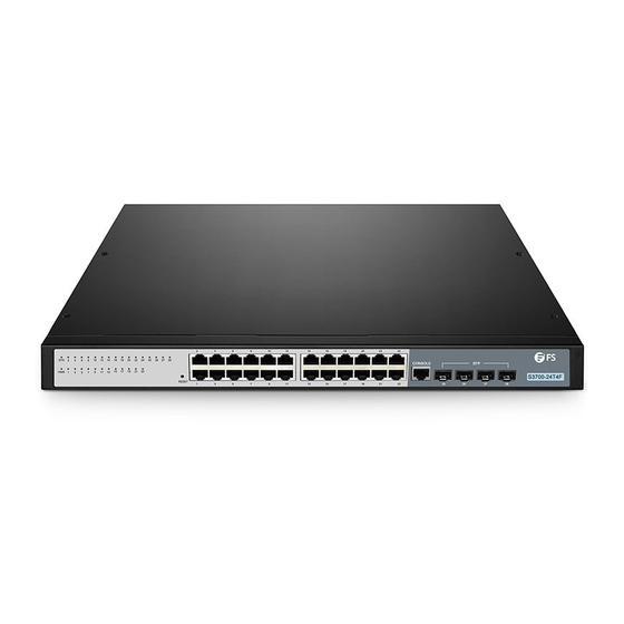
Hardware Overview Front Panel Ports RJ45 Console Ports Description RJ45 10/100/1000BASE-T ports for Ethernet connection Hot swappable SFP ports for 1G fiber connection Console An RJ45 console port for serial management Front Panel Button RESET Button Description Keep the device powered on, press the button "RESET" for 6 seconds, Reset and the system will return to the default setting. -
Page 4: Front Panel Leds
Front Panel LEDs RJ45 LEDs Status Description Green Switch is powered on. Blinking Green System is working properly. Orange 10/100M connection. RJ45 Green 1000M connection. Off No signal transmission. Green 1000M connection. Off No signal transmission. Back Panel Grounding Point Power Supply Site Environment Do not operate it in an area that exceeds an ambient temperature of 50°C. -
Page 5: Desk Mounting
Installing Desk Mounting 1. Attach four rubber pads to the bottom. 2. Place the chassis on a desk. Rack Mounting 1. Secure the mounting brackets to the two sides of the switch with eight M3 screws. -
Page 6: Grounding The Switch
2. Attach the switch to the rack using four M6 screws and cage nuts. Grounding the Switch 1. Connect one end of the grounding cable to a proper earth ground, such as the rack in which the switch is mounted. 2. -
Page 7: Connecting To The Power
Connecting to the power 1. Plug the AC power cord into the power port on the back of the switch. 2. Connect the other end of the power cord to an AC power source. WARNING: Do not install power cables while the power is on. Connecting to the RJ45 Ports 1. -
Page 8: Connecting To The Console Port
Connecting to the SFP Ports 1. Plug the compatible SFP transceiver into the SFP port. 2. Connect a fiber optic cable to the fiber transceivers. Then connect the other end of the cable to another fiber device. Connecting to the Console Port 1. -
Page 9: Configuring The Switch
Configuring the Switch Configuring the Switch Using the Web-based lnterface Step 1: Connect your computer to any Ethernet port of the switch using the network cable. Step 2: Set up the lP configuration on your computer.The lP address of your computer should be set in the same subnet addresses of the switch.The lP address is 192.168.1.x("x"... -
Page 10: Online Resources
Contact Us Product Warranty FS ensures our customers that any damage or faulty items due to our workmanship, we will offer a free return within 30 Days from the day you receive your goods. This excludes any custom made items or tailored solutions. - Page 11 Einführung Vielen Dank, dass Sie sich für den FS S3700-24T4F Full-Gigabit Access Switch entschieden haben. Diese Anleitung soll Sie mit dem Aufbau des Switches vertraut machen und beschreibt, wie Sie den Switch in Ihrem Netzwerk einsetzen. S3700-24T4F Zubehör Netzkabel x 1...
- Page 12 Hardware-Übersicht Ports an der Vorderseite RJ45 Console Ports Beschreibung RJ45 10/100/1000BASE-T-Ports für Ethernet-Anschluss Hot-Swap-fähige SFP-Ports für 1G-Glasfaseranschluss Console RJ45-Konsolenport für die serielle Verwaltung Taste an der Vorderseite RESET Taste Beschreibung Halten Sie das Gerät eingeschaltet und drücken Sie die Taste "RESET" für Reset 6 Sekunden, um das System auf die Standardeinstellung zurückzusetzen.
-
Page 13: Leds An Der Vorderseite
LEDs an der Vorderseite RJ45 LEDs Status Beschreibung Grün Der Switch ist eingeschaltet. Grün blinkend Das System arbeitet ordnungsgemäß. Orange 10/100M-Verbindung. RJ45 Grün 1000M-Verbindung. Keine Signalübertragung. Grün 1000M-Verbindung. Keine Signalübertragung. Rückseite Erdungspunkt Stromversorgung Standortumgebung Betreiben Sie es nicht in einem Bereich, der eine Umgebungstemperatur von 50 °C überschreitet. Der Installationsort muss gut belüftet sein. -
Page 14: Installation
Installation Montage auf einem Tisch 1. Bringen Sie vier Gummipads an der Unterseite an. 2. Stellen Sie das Gehäuse auf einen Tisch. Montage im Rack 1. Befestigen Sie die Montagehalterungen mit acht M3-Schrauben an den beiden Seiten des Switches. - Page 15 2. Befestigen Sie den Switch mit vier M6-Schrauben und Käfigmuttern am Rack. Erdung des Switches 1. Schließen Sie ein Ende des Erdungskabels an eine geeignete Erdung an, z. B. an das Rack, in dem der Switch montiert ist. 2. Befestigen Sie die Erdungslasche mit den Unterlegscheiben und Schrauben am Erdungspunkt an der Rückwand des Switches.
- Page 16 Anschluss an das Stromnetz 1. Stecken Sie das Netzkabel in den Netzanschluss auf der Rückseite des Switches. 2. Schließen Sie das andere Ende des Netzkabels an eine Netzstromquelle an. WARNUNG: Installieren Sie keine Netzkabel, während das Gerät eingeschaltet ist. Anschluss der RJ45-Ports 1.
- Page 17 Anschluss der SFP-Ports 1. Stecken Sie den kompatiblen SFP-Transceiver in den SFP-Port. 2. Schließen Sie ein Glasfaserkabel an die Glasfasertransceiver an. Schließen Sie dann das andere Ende des Kabels an ein anderes Glasfasergerät an. Anschluss der Konsolenports 1. Verbinden Sie die DB9-Buchse des Konsolenkabels mit der seriellen RS-232-Schnittstelle des Computers. 2.
-
Page 18: Fehlerbehebung
Konfiguration des Switches Konfiguration des Switches über die webbasierte Schnittstelle Schritt 1: Schließen Sie Ihren Computer über das Netzwerkkabel an einen beliebigen Ethernet-Anschluss des Switches an. Schritt 2: Richten Sie die lP-Konfiguration auf Ihrem Computer ein. Die lP-Adresse Ihres Computers sollte in der gleichen Subnetzadresse des Switches liegen. - Page 19 Kontakt Produktgarantie FS versichert seinen Kunden, dass alle Schäden oder fehlerhaften Artikel, die auf unsere Verarbeitung zurückzuführen sind, innerhalb von 30 Tagen ab dem Tag, an dem Sie Ihre Ware erhalten haben, kostenlos zurückgegeben werden können. Dies gilt nicht für Sonderanfertigungen oder maßgeschneiderte Lösungen.
- Page 20 Introduction Nous vous remercions d'avoir choisi le commutateur d'accès full-gigabit FS S3700-24T4F. Ce guide est conçu pour vous puissiez vous familiariser avec la configuration du commutateur et indique comment procéder à son déploiement. S3700-24T4F Accessoires Câble d'Alimentation x 1 Câble de Console x 1...
-
Page 21: Aperçu Du Matériel
Aperçu du Matériel Ports du Panneau Frontal RJ45 Console Ports Description RJ45 Ports 10/100/1000BASE-T pour connexion Ethernet Ports SFP remplaçables à chaud pour connexion fibre 1G Console Port console RJ45 pour la gestion en série Bouton du Panneau Frontal RESET Button Description Lorsque l'appareil est sous tension, appuyez sur le bouton "RESET"... -
Page 22: Panneau Arrière
Indicateurs LED de Panneau Frontal RJ45 LEDs Statut Description Vert Le commutateur est sous tension. Vert Clignotant Le système fonctionne normalement. Orange Connection 10/100M. RJ45 Vert Connection 1000M. Éteint Aucun signal de transmission. Vert Connection 1000M. Éteint Aucun siganl de transmission. Panneau Arrière Point de Mise à... -
Page 23: Montage Sur Support
Installation Montage sur Support 1. Fixez quatre coussins en caoutchouc à la base. 2. Placez le châssis sur le support. Montage sur Rack 1. Fixez les supports de montage aux deux côtés du commutateur à l'aide de huit vis M3. - Page 24 2. Fixez le commutateur au rack à l'aide de quatre vis M6 et d'écrous à cage. Mise à Terre du Commutateur 1. Connectez une extrémité du câble de mise à terre à une terre appropriée, telle que le rack sur lequel le commutateur est installé.
- Page 25 Connection de l'alimentation 1. Branchez le câble d'alimentation CA dans le port d'alimentation situé sur le panneau arrière du commutateur. 2. Connectez l'autre extrémité du câble d'alimentation à une source de courant alternatif. AVERTISSEMENT: Ne pas installer les câbles d'alimentation lorsque l'appareil est sous tension.
- Page 26 Connection aux Ports SFP 1. Branchez le module SFP compatible dans le port SFP. 2. Connectez un câble à fibre optique aux modules optiques. Puis connectez l'autre extrémité du câble à un autre dispositif à fibre. Connection au Port Console 1.
-
Page 27: Dépannage
Configuration du Commutateur Configuration du Commutateur à l'Aide de l'Interface Web Étape 1 : Connectez votre ordinateur à n'importe quel port Ethernet du commutateur à l'aide du câble réseau. Étape 2 : Définissez les paramètres de configuration lP sur votre ordinateur. L'adresse IP de votre ordinateur doit être définie dans le même sous-réseau que celui du commutateur. -
Page 28: Garantie Du Produit
_us.html Garantie du Produit FS garantit à ses clients que tout article endommagé ou défectueux dû à sa fabrication pourra être retourné gratuitement dans un délai de 30 jours à compter de la date de réception de la marchandise. -
Page 29: Compliance Information
Any changes or modifications not expressly approved by the grantee of this device could void the user's authority to operate the equipment. Responsible party (only for FCC matter) FS.COM Inc. 380 Centerpoint Blvd, New Castle, DE 19720, United States https://www.fs.com... - Page 30 Die FS.COM GmbH erklärt hiermit, dass dieses Gerät mit der Richtlinie 2014/30/EU und 2014/35/EU konform ist. Eine Kopie der EU-Konformitätserklärung finden Sie unter www.fs.com/de/company/quality_control.html. FS.COM GmbH déclare par la présente que cet appareil est conforme à la Directive 2014/30/UE et 2014/35/UE. Une copie de la Déclaration UE de Conformité est disponible sur https://www.fs.com/fr/company/quality_control.html FS.COM LIMITED...
Need help?
Do you have a question about the S3700-24T4F and is the answer not in the manual?
Questions and answers