Table of Contents
Advertisement
1
2
3
4
5
6
STA TUS
RES ET
CON SOL E
Gre en= 100 0M
Yel low =10 /10
0M
1
STA TUS PWR
2
3
1 PWR 2
4
5
ID
6
7
8
9
RES ET
CON SOL E
Gre en= 100 0M
Yel low =10 /10
0M On =Li nk
Fla shi ng= AC
S3910 Series Switches
MANAGED L2+ GIGABIT SWITCHES
Quick Start Guide
7
8
9
10
11
12
13
14
15
16
17
18
19
20
21
22
23
On =Li nk
Fla shi ng= AC
T
10
11
12
13
14
15
16
17
18
19
20
21
22
23
24
25
T
V1.0
S3 91 0-2 4T
S
24
S39 10- 24T F
25
SFP
26
27
28
26
27
28
29
30
31
32
33
34
35
36
37
38
39
40
41
42
43
44
45
46
47
48
SFP +
49
50
51
52
S3 91 0- 48
TS
Advertisement
Table of Contents

Related Manuals for FS S3910 Series


Summary of Contents for FS S3910 Series
- Page 1 1 PWR 2 RES ET CON SOL E Gre en= 100 0M Yel low =10 /10 0M On =Li nk Fla shi ng= AC SFP + S3 91 0- 48 S3910 Series Switches MANAGED L2+ GIGABIT SWITCHES Quick Start Guide V1.0...
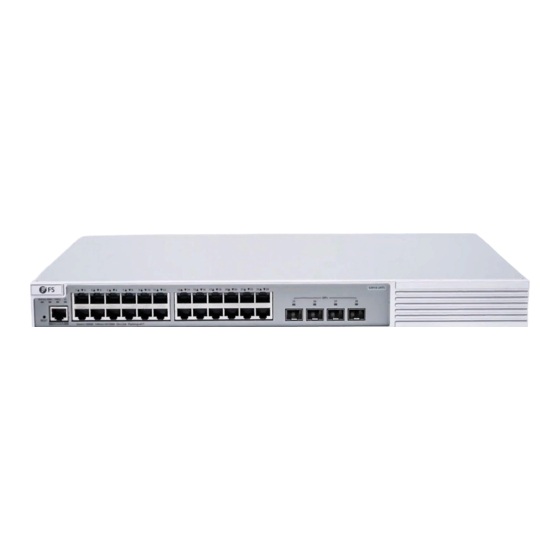
- Page 2 Introduction Thank you for choosing S3910 Series Stackable Managed Switches. This guide is designed to familiarize you with the layout of the switch and describes how to deploy the switch in your network. S3910-24TF S3910-24TF STATUS RESET CONSOLE Green=1000M Yellow=10/100M...
-
Page 3: Hardware Overview
Grounding Cable x1 Rubber Pad x4 Mounting Bracket x2 M4 Screw x8 NOTE: S3910 series switches have dust plugs delivered with them. Keep the dust plugs properly and use them to protect idle optical ports. Hardware Overview Front Panel Ports S3910-24TF... -
Page 4: Front Panel Button
S3910-24TS S3910-24TS STATUS PWR1 PWR2 SFP+ RESET CONSOLE Flashing=ACT Green=1000M Yellow=10/100M On=Link CONSOLE RJ45 SFP+ S3910-48TS SFP+ STATUS PWR1 PWR2 RESET CONSOLE S3910-48TS Green=1000M Yellow=10/100M On=Link Flashing=ACT CONSOLE RJ45 SFP+ Ports Description 10/100/1000BASE-T ports for Ethernet connection RJ45 SFP+ ports for 1/10G connection SFP+ An RJ45 console port for serial management CONSOLE... - Page 5 Back Panels S3910-24TF Cable Clamps Holes Grounding Point Power Supply S3910-24TS/S3910-48TS PWR2 PWR1 Dual Power Supplies Grounding Point Front Panel LEDs S3910-24TF STATUS RJ45 S3910-24TF STATUS RESET CONSOLE Green=1000M Yellow=10/100M On=Link Flashing=ACT LEDs Status Description Switch is not receiving power. Blinking Green System is being initialized.
- Page 6 LEDs Status Description The port is not connected. Solid Green The port is connected at 1000 Mbps. Solid Yellow The port is connected at 10/100 Mbps. RJ45 Blinking Green The port is receiving or transmitting tra c at 1000 Mbps. Blinking Yellow The port is receiving or transmitting tra c at 10/100 Mbps.
- Page 7 LEDs Status Description Switch is not receiving power. Blinking Green System is being initialized. Solid Green Switch is operational. Moderate temperature warning: STATUS Solid Yellow Check the working environment of the switch immediately. 1. Severe temperature warning: The temperature severely exceeds the temperature limit, so Solid Red the system is going to restart.
-
Page 8: Installation Requirements
Installation Requirements Before you begin the installation, make sure that you have the followings: Phillips screwdriver. Standard-sized, 19" wide rack with a minimum of 1U height available. Category 5e or higher RJ-45 Ethernet cables, ber optical cables and console cable for connecting network devices. -
Page 9: Mounting The Switch
Mounting the Switch ST AT US PW R1 PW R2 Desk Mounting RE SE T C O N SO LE G re e n = 1 0 0 0 M Y e llo w = 1 0 /1 0 0 M O n = Li n k F la sh in g = A C T... -
Page 10: Wall Mounting
S F P + S 3 9 1 0 -4 8 2. Attach the switch to the rack using four M6 screws and cage nuts. Wall Mounting SF P+ S 3 9 1 0 -4 8 S 3 9 1 0 -4 8 1. - Page 11 2. Use the expansion screws to securely attach the mounting brackets on the wall. NOTE: Suitable for mounting on concrete or other non-combustible surface only.
-
Page 12: Installing The Power Supply Module
Installing the Power Supply Module S3910-48TS/S3910-24TS P W R 1 P W R 2 1. Take a new power module out of the package. 2. Take the plane printed with power information as the top panel of the power module. Hold the handle of the power module with one hand, and hold the end of the power module with the other hand. -
Page 13: Grounding The Switch
Grounding the Switch 1. Connect one end of the grounding cable to a proper earth ground, such as the rack in which the switch is mounted. 2. Secure the grounding lug to the grounding point on the switch back panel with the washers and screws. - Page 14 Connecting the RJ45 Ports S 3 9 0 0 -2 4 T 4 S 1. Connect an Ethernet cable to the RJ45 port of a computer, printer, network storage, or other network devices. 2. Connect the other end of the Ethernet cable to the RJ45 port of the switch. Connecting the SFP/SFP+ Ports S FP + S 3 9 1 0 -4 8...
-
Page 15: Connecting The Console Port
Connecting the Console Port ST AT US PW R1 PW R2 RE SE T CO NS OL E Gr ee n= 10 00 M Ye llo w =1 0/ 10 0M On =L in k Fl as hi ng =A CT 1. -
Page 16: Stacking The Switches
Stacking the Switches The S3910 series switches support stacking up to 4 units. Switches in the series can be physically stacked using optical ber cables connected to SFP/SFP+ transceivers or 1/10G Direct Attach Cables (DAC). SFP+ STATUS PWR1 PWR2 RESET... -
Page 17: Configuring The Switch
Configuring the Switch Configuring the Switch Using the Web-based Interface Step 1: Connect the computer to the business port of the switch using the network cable. Step 2: Set the IP address of the computer to 192.168.1.x. (“x” is any number from 2 to 254.) I nter n et Protocol Ver si on 4 ( TC P/IP v 4) Prope r tie s General Yo u c a n g e t I P s e t t i n g s a s s i g n e d a u t o m a t i c a l l y i f y o u r n e t w o r k... - Page 18 Configuring the Switch Using the Console Port Step 1: Connect a computer to the switch's console port using the console cable. Step 2: Start the terminal simulation software such as HyperTerminal on the computer. Step 3: Set the parameters of the HyperTerminal: 9600 bits per second, 8 data bits, no parity, 1 stop bit and no ow control.
-
Page 19: Troubleshooting
1. Ensure the switch ports are in the no shutdown state. 2. Check if the switch can read the DDM information. 3. Check if the port speed setting is correct. 4. Try looping the switch cable. Support and Other Resources https://www.fs.com/download.html Download https://www.fs.com/service/help_center.html Help Center https://www.fs.com/contact_us.html... -
Page 20: Product Warranty
Product Warranty FS ensures our customers that any damage or faulty items due to our workmanship, we will o er a free return within 30 Days from the day you receive your goods. This excludes any custom made items or tailored solutions.
Need help?
Do you have a question about the S3910 Series and is the answer not in the manual?
Questions and answers