Table of Contents
Advertisement
Quick Links
3-Phase Digital Microstep Drive
©2021 Leadshine Technology Co., Ltd.
Address: 15-20/F, Block B, Nanshan I Valley, No.3185, Shahe West Road, Nanshan District, Shenzhen,
Tel: (86)755-26409254
Web:
www.leadshine.com
Support:
tech@leadshine.com
User Manual
3DM580S
Revision 1.0
Guangdong, 518055, China
I
3DM580S 3-Phase Digital Stepper Drive User Manual
Fax: (86)755-26402718
Sales:
sales@leadshine.com
Advertisement
Table of Contents

Related Manuals for Leadshine Technology 3DM580S


Summary of Contents for Leadshine Technology 3DM580S
- Page 1 3DM580S 3-Phase Digital Stepper Drive User Manual User Manual 3DM580S 3-Phase Digital Microstep Drive Revision 1.0 ©2021 Leadshine Technology Co., Ltd. Address: 15-20/F, Block B, Nanshan I Valley, No.3185, Shahe West Road, Nanshan District, Shenzhen, Guangdong, 518055, China Tel: (86)755-26409254...
- Page 2 3DM580S 3-Phase Digital Stepper Drive User Manual Important Notice Read this manual carefully before any assembling and using. Incorrect handling of products in this manual can result in injury and damage to persons and machinery. Strictly adhere to the technical information regarding installation requirements.
-
Page 3: Table Of Contents
3DM580S 3-Phase Digital Stepper Drive User Manual Table of Contents 1. Introduction......................................1 1.1 Features.......................................1 1.2 Applications....................................1 2.Specifications......................................1 2.1 Electrical Specifications................................1 2.2 Environment....................................2 2.3 Mechanical Specifications................................. 2 2.4 Elimination of Heat..................................2 3. Connection Pin Assignments and LED Indication.........................3 3.1 P1&... -
Page 4: Introduction
3DM580S 3-Phase Digital Stepper Drive User Manual 1. Introduction The 3DM580S is Leadshine newest digital stepper drive based on an advanced control algorithm. It brings a unique level of system smoothness, providing optimum torque and nulls mid-range instability. Motor self-test and parameter auto-setup technology offers optimum responses with different motors and easy-to-use. -
Page 5: Environment
3DM580S 3-Phase Digital Stepper Drive User Manual 2.2 Environment Cooling Natural Cooling or Forced cooling Avoid dust, oil fog and corrosive gases Environment 0 - 65°C (32 - 149°F) Ambient Temperature 40 - 90%RH Operating Environment Humidity Operating Temperature 0 - 50°C (32 - 122°F) Vibration 10-50Hz / 0.15mm... -
Page 6: Connection Pin Assignments And Led Indication
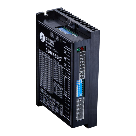
Figure 2 Connectors, DIP switches, and LED locations The 3DM580S has 4 connectors P1, P2, P3 and P4, 2 DIP switches S1and S2. P1 is for control signal connections, P2 is for fault output, P3 is for power and motor connection, P4 is for fine tuning. -
Page 7: P3 - Power And Motor Connector
Motor phase W 3.3 P4 - Tuning Port 3DM580S has a tuning port with RS232 to modify the drive parameters, it’s only for tuning, not for equipment control because neither precision nor stability is sufficient. The interface definition is as follows: Figure 3 Tuning Port 3.4 Status LED (Protection Functions) -
Page 8: Control Signal And Fault Output Wiring
4.2 Fault Output Connection When over voltage or over current protection happens, 3DM580S red status LED light will blink and the impedance state between ALM+ and ALM- will change (from low to high or high to low depending on configuration) and can thus be detected. -
Page 9: Sequence Chart Of Control Signals
3DM580S 3-Phase Digital Stepper Drive User Manual Figure 5 Fault output connections 4.3 Sequence Chart of Control Signals In order to avoid some fault operations and deviations, PUL, DIR and ENA should abide by some rules, shown as following diagram:... -
Page 10: Dip Switch Configurations
5.1 Output Current (SW1-SW4) The 3DM580S has 8 output current settings which can be configured through DIP switch SW1, SW2, SW3 and SW4. For a given stepper motor, as normal setting the output current to 1.4 times of motor phase current, will make it output larger torque, but at the same time cause more heating for both the motor and drive. -
Page 11: Standstill Current Setting (Sw5)
5.2 Standstill Current Setting (SW5) The SW5 of an 3DM580S is used to set output current percentage when motor is standstill. Idle current percentage will be set to 50% at OFF position, and 90% at ON position. When the driven stepper motor is idle (no movement) for 0.4 second, the output current of 3DM580S will be automatically reduced to the configured percentage. -
Page 12: Motion Mode Configuration (Sw11)
6. Power Supply Selection The 3DM580S can power small and medium size 3-phase stepper motors (frame size from NEMA17 to 34) from Leadshine or other motor manufacturers. To get good system performance, it is important to select proper supply voltage and output current. -
Page 13: Regulated Or Unregulated Power Supply
6.2 Power Supply Sharing Multiple 3DM580S drives can share one power supply to save space and reduce cost, if that power supply has enough power capacity. To avoid cross interference, connect each stepper drive directly to the shared power supply separately. To avoid cross interference, DO NOT daisy-chain connect the power supply input pins of the Drivers. -
Page 14: Motor Selection
7. Motor Selection The 3DM580S can be used to drive 3- or 6-wire three-phase hybrid stepper motors with a step angle of 1.2 degrees. The choice of motor is mainly determined by the motor torque and current rating. The torque size is mainly determined by the size of the motor. -
Page 15: Warranty
Twelve Month Warranty Leadshine Technology Co., Ltd. warrants its products against defects in materials and workmanship for a period of 12 months from shipment out of factory. During the warranty period, Leadshine will either, at its option, repair or replace products which proved to be defective.
Need help?
Do you have a question about the 3DM580S and is the answer not in the manual?
Questions and answers