Table of Contents
Advertisement
Quick Links
EM542S Digital Stepper Drive User Manual
User Manual
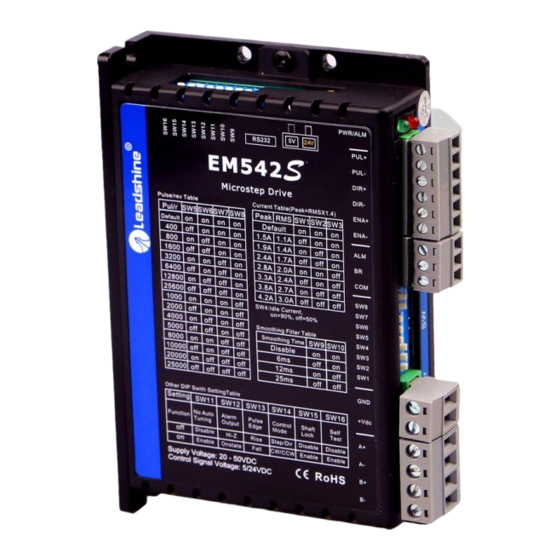
EM542S
Digital Microstep Drive
Revision 3.0
©2019 Leadshine Technology Co., Ltd.
Address: Floor 11, Block A3, Nanshan iPark, Xueyuan Avenue 1001, Shenzhen, Guangdong, 518055, China
Tel: (86)755-26409254
Fax: (86)755-26402718
Web:
Sales:
www.leadshine.com
sales@leadshine.com
Support:
tech@leadshine.com
Advertisement
Table of Contents

Subscribe to Our Youtube Channel
Related Manuals for Leadshine Technology EM556S


Summary of Contents for Leadshine Technology EM556S
- Page 1 EM542S Digital Stepper Drive User Manual User Manual EM542S Digital Microstep Drive Revision 3.0 ©2019 Leadshine Technology Co., Ltd. Address: Floor 11, Block A3, Nanshan iPark, Xueyuan Avenue 1001, Shenzhen, Guangdong, 518055, China Tel: (86)755-26409254 Fax: (86)755-26402718 Web: Sales: www.leadshine.com sales@leadshine.com...
- Page 2 EM542S Digital Stepper Drive User Manual Important Notice Read this manual carefully before any assembling and using. Incorrect handling of products in this manual can result in injury and damage to persons and machinery. Strictly adhere to the technical information regarding installation requirements.
-
Page 3: Table Of Contents
EM542S Digital Stepper Drive User Manual Table of Contents 1.Introduction..................................1 1.1 Features...................................1 1.2 Applications................................1 2.Specifications..................................2 2.1 Electrical Specifications............................2 2.2 Environment................................2 2.3 Mechanical Specifications............................2 2.4 Elimination of Heat..............................3 3. Connection Pin Assignments and LED Indication...................... 3 3.1 P1 - Control Connector Configurations........................3 3.2 P2 - Fault and Brake Output Connector......................... -
Page 4: Introduction
EM542S Digital Stepper Drive User Manual 1. Introduction The EM542S is a new digital stepper drive based on Leadshine’s widely implemented DM stepper drives (10+ millions of units in field). While retaining features of simple design, easy setup, high precision and reliability, Leadshine has also upgraded it by adopting the latest stepper control technology and added additional advanced features for better torque (10-25%), quicker response time, control command smoothing, easy self-test, etc. -
Page 5: Specifications
EM542S Digital Stepper Drive User Manual 2. Specifications 2.1 Electrical Specifications Parameters Typical Unit Output Current 4.2 (3.0 RMS) Supply Voltage 24 - 48 Logic signal current Pulse input frequency Minimal pulse width μs Minimal direction setup μs Isolation resistance MΩ... -
Page 6: Elimination Of Heat
EM542S Digital Stepper Drive User Manual 2.4 Elimination of Heat EM542S’s working temperature is less than 60℃ (140°F) It is recommended to use automatic idle-current mode to reduce motor heating. That means set the SW4 pin of DIP switch at “OFF” position. It is recommended to mount the drive vertically to maximize heat sink area. -
Page 7: P2 - Fault And Brake Output Connector
EM542S Digital Stepper Drive User Manual 3.2 P2 - Fault and Brake Output Connector Details Output Connection: Optional. (1) Maximum 30V/100mA output (2) Sinking or sourcing (3) The resistance between ALM and COM- is low impedance as default (configurable by DIP switch SW12), and will change to high when the drive goes into error protection. -
Page 8: Control Signal And Fault Output
EM542S Digital Stepper Drive User Manual 4. Control Signal and Fault Output 4.1 Control Signal Connection The EM542S can accept differential or single-ended control signals (pulse, direction, and enable) in open-collector or PNP connection through the P1 connector (figure 2). It is recommend to add an EMI line filter between the power supply and the drive to increase noise immunity for the drive in interference environments. -
Page 9: Stepper Motor Connections
EM542S Digital Stepper Drive User Manual Figure 7 Brake Output Connection 5. Stepper Motor Connections EM542S can drive 2-phase and 4-phase bipolar hybrid stepper motors with 4, 6, or 8 leads, Leadshine also offers easy-to-use and good-performance motors with 4-lead that have been tested with EM542S: (http://www.leadshine.com/series.aspx?type=products&category=stepper-products&producttype=stepper-motors&subt ype=hybrid-stepper-motors&series=cm) 5.1 4-lead Motor Connection (recommended) -
Page 10: 8-Lead Motor Connection
EM542S Digital Stepper Drive User Manual 5.3 8-lead Motor Connection EM542S can power 8-lead in series or parallel connection in series or parallel. Series connected 8-lead stepper motors are typically implemented in applications which higher torque at lower speed movement is required. Because a stepper motors under series connection has the most inductance, the performance will start to degrade when the motor runs at higher speed. -
Page 11: Power Supply Sharing
EM542S Digital Stepper Drive User Manual 6.2 Power Supply Sharing Multiple EM542S drives can share the same power supply, if that power supply has enough capacity. To avoid cross interference, connect each EM542S DIRECTLY to that shared power supply separately instead of connecting those power connectors of drives in daisy-chain connection. -
Page 12: Idle Current Configuration (Sw4)
EM542S Digital Stepper Drive User Manual The SW1, SW2 and SW3 are used to set the dynamic current. Select a setting closest to your motor’s required current. When they are set to ON, ON, ON, the output current can be set by Leadshine ProTuner. Peak Current RMS Current 1.0A... -
Page 13: Smoothing Filter Time Configuration (Sw9-10)
EM542S Digital Stepper Drive User Manual 7.4 Smoothing Filter Time Configuration (SW9-10) EM542S has an advanced feature called control command smoothing to make the input pulse from pulse generator (controller, PLC, etc.) S-curve acceleration, to improve motion smoothness and high-speed start frequency in many circumstances. -
Page 14: Wiring Notes
EM542S Digital Stepper Drive User Manual switch position to OFF for normal operation. 8. Wiring Notes In order to improve anti-interference performance of the drive, it is recommended to use twisted pair shield cable. To prevent noise incurred in PUL/DIR signal, pulse/direction signal wires and motor wires should not be tied up ... -
Page 15: Protection Functions
EM542S Digital Stepper Drive User Manual Figure 13 Sequence chart of control signals Remark: : ENA must be ahead of DIR by at least 5s. Usually, ENA+ and ENA- are NC (not connected). See “Connector P1 Configurations” for more information. : DIR must be ahead of PUL effective edge by 5s to ensure correct direction;... -
Page 16: Troubleshooting
EM542S Digital Stepper Drive User Manual 12. Troubleshooting In the event that your drive doesn’t operate properly, the first step is to identify whether the problem is electrical or mechanical in nature. The next step is to isolate the system component that is causing the problem. As part of this process you may have to disconnect the individual components that make up your system and verify that they operate independently. -
Page 17: Warranty
Twelve Month Warranty Leadshine Technology Co., Ltd. warrants its products against defects in materials and workmanship for a period of 12 months from shipment out of factory. During the warranty period, Leadshine will either, at its option, repair or replace products which proved to be defective.
Need help?
Do you have a question about the EM556S and is the answer not in the manual?
Questions and answers